Roga VC-02 User manual

Model VC-02 VibrationCalibrator Version AEditDate 20/04/2015
2/8
Index
1Overview......................................................................................................................... 3
2 TechnicalSpecifications...............................................................................................3
3HowtoOperate..............................................................................................................5
4SoftwareOperation....................................................................................................... 8
5Accessories.............................................................................................................8
Notes:
Asaprecisioninstrument,besuretoreadthemanual
carefullybeforeusing.
Thewarrantyperiodis18months,ifanyproblems,
pleasecontactus.

Model VC-02 VibrationCalibrator Version AEditDate 20/04/2015
3/8
1Overview
VC-02vibrationcalibratorconsistsofthestandardsensor,signalgenerators,
poweramplifiers,signalconditioninganddigitalcontroldisplaycircuitwithasmall,
solidandstablestructure.Itisafull-functionsvibrationcalibratorforindustrialfield
orlaboratory;Highprecision,simpleoperation,easytouse.Itcancalibratea
varietyoftypesofvibrationsensorssuchasaccelerationsensors,magnetic
velocitysensorsandeddydisplacementsensors,andcalibratesomevibration
monitoringsystemsanddataacquisitionsystem.
2TechnicalSpecifications
2.1Accuracy: 5%
2.2Vibration signal frequency: 10Hz-10kHz (sinusoidal signal),
frequencyaccuracy:<0.05Hz
2.3MaximumLoad:200g
2.4measuredsensortype:
2.4.1 ChargeModeAccelerometers
2.4.2 IEPEModeAccelerometers
2.4.3 VoltageOutputModeAccelerometers
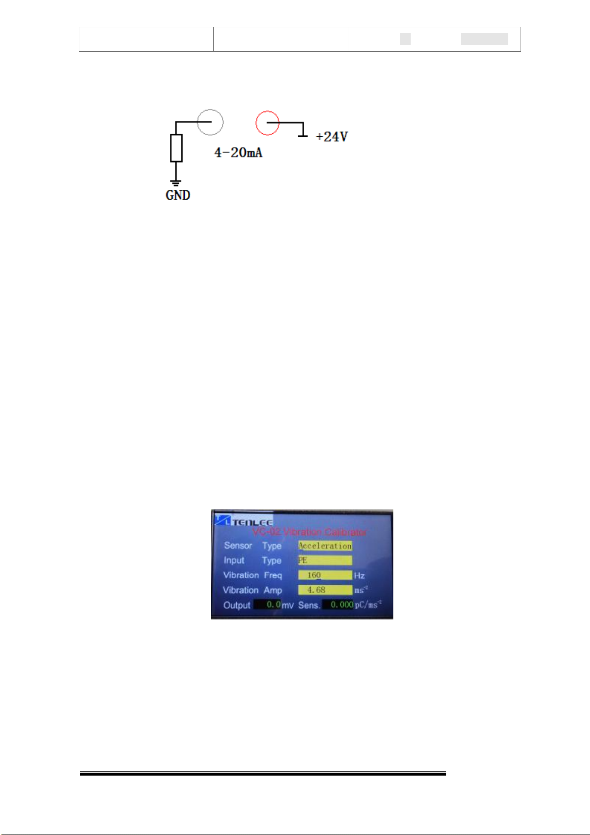
2.4.4 4-20mAOutputModeAccelerometersorVelocitySensors
2.4.5 EddyDisplacementSensors
2.5MaximumInputRange:
2.5.1 ChargeMode: ≤ 3000pC;
2.5.2 Voltage(IEPE)Mode: ≤ 3000mV
2.6VibrationAmplituderange(RMS):
2.6.1 Acceleration: ≤50.00m/s2
2.6.2 Velocity:≤150.00mm/s
2.6.3 Displacement: ≤1500μm
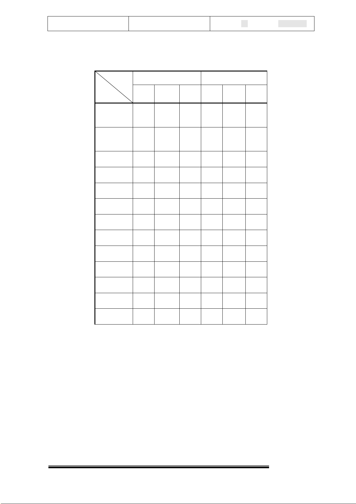
2.7MaximumVibrationAmplitude&MaximumLoad
FortheVC-02issmall,sothecalibrationofthedifferentsensorsat
differentfrequencies(differentweight),thecalibratorcanoutput
amplitudeisnotthesame.Themaximumvibrationamplitudeandthe
maximumloadatacertainfrequency,isasfollows:Allvalues

Model VC-02 VibrationCalibrator Version AEditDate 20/04/2015
4/8
areRMS.
Load
Frequency
≤100grams ≤200grams
a(m/S2)v(mm/S) d(μm) a(m/S2)v(mm/S
)d(μm)
10Hz 10 100 150
010 100 150
0
20Hz 20 150 120
020 150 1200
40Hz 50 200 800 30 100 500
80Hz 50 100 200 30 60 120
160Hz 50 50 50 30 30 30
320Hz 50 25 12 30 15 7
640Hz 50 12 3 40 10 2.5
1kHz 50 8 * 40 6 *
2kHz 50 4 * 30 2.4 *
4kHz 50 2 * 30 * *
6kHz 50 * * 30 * *
8kHz 50 * * 30 * *
10kHz 50 * * 30 * *
*Athighfrequencies,thevibrationvalueofvelocityanddisplacementisvery
small.
2.8 MountingType M5screw
2.9Workingtemperature:0℃to+55℃;HumidityMaximum95%R.H.
2.10PowerSupply AC220V 10%50~60Hz
2.11Size 300mm×210mm×130mm
2.12Weight about6.5Kg

Model VC-02 VibrationCalibrator Version AEditDate 20/04/2015
5/8
3HowtoOperate
3.1ThePanelDiagram
1. Powerinputsocket:connecttheAC220Vpowersupply;
2. PowerSwitch:AC220Vpowerswitch
3. USBinterfaces:ConnectthePCforvibrationcontrolbysoftware;
4. Thetestingsensorsignaloutputsocket:thetestingsensorsignal
outputcanbemeasuredbyadigitalmulti-meterorotherinstruments
throughthissocket;
5. Themountingscrewsforeddy sensors:thetesting bracketcanbe
mounted onthecalibrationinstrumentpanelviathescrewholesfor
testingtheeddycurrentsensors;
6. Thetable:forfixingadjustedsensors;
7. Inputsocket:connecttheoutputoftheadjustedsensors;
8. 4~20mAinputterminals:connecttheoutputof4~20mAoutput
sensors;
9. -24Vpowersupply:offerthepowerfortestingthesensorssuchas
eddysensors;
10.Vibrationamplitudeadjustmentknob

Model VC-02 VibrationCalibrator Version AEditDate 20/04/2015
6/8
11.Vibrationamplitudeadjustmentknob
12.Vibrationfrequencyadjustmentknob
13.LCDwindow
3.2 OperationSteps
3.2.1 MountingSensor
3.2.1.1Sensor(AccelerationorVelocity)installation:puttheM5
screw,sensorfixedonthetableinturn.Differentsensors,
sometimesneedtousethecorrespondingconversionscrew;
3.2.1.2Theeddysensorinstallation:Putthebenchmarkonthetest
plate,theeddysensorfixedsuiteinsequence;
3.2.1.3 Whencalibrating,placethecalibratorstableaspossible.
Whenchangethesensor,needtoturnoffthepowersupply.
Afterthecalibration,thesensorshouldberemovedforavoiding
thesensorisleftforalongtimeonthetable.
3.2.2 CableConnection
3.2.2.1 Thecalibratorcanmeasureanddisplaythevalueof
measuredsensoroutput,sotheoutputofthesesensorsuchas
chargemode,IEPEmodeandVoltagemodecanbeconnected
tothesocketofsignalinputsocket(BNC);
3.2.2.2 Fortheoutputof4-20mAsensor,pleaseconnectthesignal
to"4-20mA"terminal,internalcalibrationinstrumentisillustrated

Model VC-02 VibrationCalibrator Version AEditDate 20/04/2015
7/8
below.
3.2.2.3 Foreddydisplacementsensor,thecalibratorcanofferthe
powertothepreamplifier;Thegreenterminalis-24VDC,the
blackoneis0V;Andtheoutputofpreamplifierconnecttothe
signalsocketoftheBNC;
3.2.2.4 Ifhopetomeasuretheoutputsignalof adjustedsensor,
pleasecheckthesocketofsensoroutputsignal–(BNC);For
thissignalcanbeadjustedautomaticbythecalibrator,sothe
outputsignalshouldbeamplifiedX1orX10.
3.2.2.5 ConnecttoACPower:PleaseconfirmtheACpowersupply
shouldbe220V/50Hz;
3.2.2.6 IfhopetooperatebyPC,connectthecalibratortoPCbyone
USBcable.
3.2.3 OperationSetting
Aftercheckingcablesandsensorsbefixedcorrectly,turnonthe
powerandtheLCDwilldisplayasfollows:
3.2.3.1 SensorType canselectthetypeoftestedsensorsuchas
Acceleration,VelocityandDisplacement.
3.2.3.2 InputType:selecttheinputtypeoftestedsensorsuchasPE(Charge
Mode),IEPEMode,VoltageModeand4-20mAoutputMode.

Model VC-02 VibrationCalibrator Version AEditDate 20/04/2015
8/8
SettingMethod:Presstheknob ,canchange<SensorType>or<Input
Type>,andcounterclockwiseorclockwisethisknob ,canchangethetypes
ofcurrentlocation.
3.2.3.3 VibrationFreq:VibrationFrequencyadjustment
SettingMethod:Presstheknob tochangethecursorposition;counter
clockwiseorclockwiseadjustthisknob ,setthefrequency;
3.2.3.4 VibrationAmp:VibrationAmplitudeadjustment
3.2.3.5 Settingmethod:Turnthisknob counterclockwise,canbe
reducedvibrationamplitude;AndTurnthisknob clockwise,can
addvibrationamplitude.LCDdisplaysthisRMSValueofvibration
amplitude.Pleasenotetheamplitudecannotoverthemaximumrated
outputamplitude;whenfinished,pleasesettheamplitudetoa
minimumlevel.
3.2.3.6 Output:theoutputofadjustedsensors,thevalueisRMS;
3.2.3.7 Sens.:Thesensitivityofcalibratedsensor.
4SoftwareOperation
Pleaseseethesoftwareuserguide.
5Accessories
5.1UserGuide:1
5.2 Certificate :1
5.3InputCables:4
5.4OutputCables:1
5.5 PowerCable:1
Table of contents
Other Roga Test Equipment manuals