Roger Technology BIONIK8 Product manual

BIONIK8
Barriera automatica Brushless
Automatic barrier Brushless
Automatisierung für Schranke Brushless
Barrière automatique Brushless
Barrera automática Brushless
Barreira automática Brushless
IT - Manuale di installazione
EN - Instruction and warnings for the installer
DE - Anleitungen und Hinweise für den Installateur
FR - Instructions et avertissements pour l'installateur
ES - Instrucciones y advertencias para el instalador
PT - Instruções e avisos para o instalador
IS194 Rev.00 17/10/2018

2
IT
EN
DE
FR
ES
PT
1 AVVERTENZE GENERALI 3
2 DICHIARAZIONE DI CONFORMITÀ 3
3 DESTINAZIONE D’USO 3
4 LIMITI DI IMPIEGO 3
5 DESCRIZIONE DEL PRODOTTO 4
6 DIMENSIONI 4
7 CONTENUTO DELL’IMBALLO 4
8 CARATTERISTICHE TECNICHE 5
9 INSTALLAZIONE TIPO 5
10 RIFERIMENTI E ACCESSORI 6
11 INSTALLAZIONE 7
11.1 Verifiche preliminari 7
11.2 Installazione piastra di base 7
11.3 Installazione barriera 8
11.4 Selezione senso di apertura 9
12 INSTALLAZIONE DELL’ASTA 10
12.1 Preparazione asta D1 10
12.2 Preparazione asta D2 10
12.3 Procedura di installazione 11
13 INSTALLAZIONE E REGOLAZIONE DELLA MOLLA 12
13.1 Installazione e regolazione del gruppo di bilanciamento 13
Il gruppo di bilanciamento è composto da bilanciere, cursore [CU] e gruppo molle. 13
13.2 Scelta del cursore 13
13.3 Installazione gruppo molle 14
13.4 Regolazione delle molle 15
14 REGOLAZIONE FERMO MECCANICO 16
15 INSTALLAZIONE DEL SISTEMA DI SBLOCCO 16
16 COLLEGAMENTO FOTOCELLULE 17
17 COLLEGAMENTI ELETTRICI 18
18 INSTALLAZIONE KIT BATTERIE (OPZIONALI) 18
19 INSTALLAZIONE LAMPEGGIANTE A LED BI/BLED/8 (fig. 26-27) 19
20 PIANO DI MANUTENZIONE 20
21 SMALTIMENTO 20
22 INFORMAZIONI AGGIUNTIVE E CONTATTI 20
23 OPERAZIONE DI SBLOCCO / BLOCCO 20
1 GENERAL SAFETY PRECAUTIONS 21
2 DECLARATION OF CONFORMITY 21
3 INTENDED USE 21
4 LIMITATIONS USE 21
5 DESCRIPTION OF THE PRODUCT 22
6 STANDARD DIMENSIONS 22
7 PACKAGE CONTENT 22
8 TECHNICAL CHARACTERISTICS 23
9 TYPICAL INSTALLATION 23
10 REFERENCES AND ACCESSORIES 24
11 INSTALLATION 25
11.1 Preliminary checks 25
11.2 Installing base plate 25
11.3 Installing the barrier 26
11.4 Selecting direction of aperture 27
12 INSTALLING THE BOOM 28
12.1 D1 boom preparation (fig. 9) 28
12.2 D2 boom preparation (fig. 10) 28
12.3 Installation procedure 29
13 INSTALLING AND ADJUSTING THE SPRING 30
13.1 Installation and adjustment of the balancing unit 31
13.2 Slider selection 31
13.3 Spring unit installation 32
13.4 Spring adjustment 33
14 ADJUSTING THE MECHANICAL STOP 34
15 INSTALLING THE LOCK RELEASE SYSTEM 34
16 CONNECTING PHOTOCELLS 35
17 ELECTRICAL CONNECTIONS 36
18 INSTALLING THE BATTERY KIT (OPTIONAL) 36
19 INSTALLING THE BI/BLED/8 LED FLASHING LIGHT (fig. 26-27) 37
20 MAINTENANCE 38
21 DISPOSAL 38
22 ADDITIONAL INFORMATION AND CONTACT 38
23 RELEASE AND LOCK PROCEDURE 38
1 ALLGEMEINE SICHERHEITSHINWEISE 39
2 KONFORMITÄTSERKLÄRUNG 39
3 NUTZUNGSBEDINGUNGEN 39
4 GEBRAUCHSBEGRENZUNG 39
5 BESCHREIBUNG DES PRODUKTS 40
6 ABMESSUNGEN 40
7 INHALT DER VERPACKUNG 40
8 TECHNISCHE DATEN 41
9 TYPISCHE INSTALLATION 41
10 HINWEISE UND ZUBEHÖR 42
11 INSTALLATION 43
11.1 Vorab-Prüfungen 43
11.2 Installazione piastra di base 43
11.3 Installation der Schranke 44
11.4 Wahl der Öffnungsrichtung 45
12 INSTALLATION DES SCHLAGBAUMS 46
12.1 D1 Schlagbaums Vorbereitung (Abb. 9) 46
12.2 D2 Schlagbaums Vorbereitung (Abb. 10) 46
12.3 Installationsverfahren 47
13 INSTALLATION UND EINSTELLUNG DER FEDER 48
13.1 Installation und Einstellung der Ausgleichseinheit 49
13.2 Auswahl des Gleitstücks 49
13.3 Installation der Federeinheit 50
13.4 Einstellung der Federn 51
14 EINSTELLUNG MECHANISCHER FESTSTELLER 52
15 INSTALLATION DES ENTRIEGELUNGSSYSTEMS 52
16 ANSCHLUSS DER LICHTSCHRANKEN 53
17 ELEKTRISCHE ANSCHLÜSSE 54
18 INSTALLATION AKKUSATZ (OPTIONAL) 54
19 INSTALLATION LED-BLINKLEUCHTE BI/BLED/8 (FIG. 26-27) 55
20 WARTUNGSPLAN 56
21 ENTSORGUNG 56
22 ZUSÄTZLICHE INFORMATIONEN UND KONTAKTE 56
23 ENTRIEGELUNG UND VERRIEGELUNG 56
1 CONSIGNES GÉNÉRALES DE SÉCURITÉ 57
2 DÉCLARATION DE CONFORMITÉ 57
3 Destination d’utilisation 57
4 Limites d’emploi 57
5 DESCRIPTION DU PRODUIT 58
6 DIMENSIONS 58
7 CONTENU DE L’EMBALLAGE 58
8 CARACTÉRISTIQUES TECHNIQUES 59
9 INSTALLATION TYPE 59
10 REFERENCES ET ACCESSOIRES 60
11 INSTALLATION 61
11.1 Vérifications préliminaires 61
11.2 Installation de la plaque de base 61
11.3 Installation de la barrière 62
11.4 Sélection du sens d’ouverture 63
12 INSTALLATION DE LA BARRE 64
12.1 Préparation de la barre D1 (fig. 9) 64
12.2 Préparation de la barre D2 (fig. 10) 64
12.3 Procédure d’installation 65
13 INSTALLATION ET RÉGLAGE DU RESSORT 66
13.1 Installation et réglage du groupe d’équilibrage 67
13.2 Choix du curseur 67
13.3 Installation du groupe ressorts 68
13.4 Réglage des ressorts 69
14 RÉGLAGE DE LA BUTÉE MÉCANIQUE 70
15 INSTALLATION DU SYSTÈME DE DÉVERROUILLAGE 70
16 RACCORDEMENT DES PHOTOCELLULES 71
17 RACCORDEMENTS ÉLECTRIQUES 72
18 INSTALLATION DU KIT BATTERIES (EN OPTION) 72
19 INSTALLATION DU FLASH CLIGNOTANT À LED BI/BLED/8 (fig. 26-27) 73
20 PLAN DE MAINTENANCE 74
21 ÉLIMINATION 74
22 INFORMATIONS COMPLÉMENTAIRES ET CONTACTS 74
23 OPÉRATIONS DE DÉBLOCAGE ET BLOCAGE 74
1 ADVERTENCIAS GENERALES 75
2 DECLARACIÓN DE CONFORMIDAD 75
3 USO PREVISTO 75
4 LÍMITES DE USO 75
5 DESCRIPCIÓN DEL PRODUCTO 76
6 DIMENSIONES 76
7 CONTENIDO DEL EMBALAJE 76
8 CARACTERÍSTICAS TÉCNICAS 77
9 INSTALACIÓN BÁSICA 77
10 REFERENCIAS Y ACCESORIOS 78
11 INSTALACIÓN 79
11.1 Controles preliminares 79
11.2 Instalación de la placa de base 79
11.3 Instalación de la barrera 80
11.4 Selección del sentido de apertura 81
12 INSTALACIÓN DEL ASTA 82
12.1 Preparación del asta D1 (fig. 9) 82
12.2 Preparación del asta D2 (fig. 10) 82
12.3 Procedimiento de instalación 83
13 INSTALACIÓN Y AJUSTE DEL MUELLE 84
13.1 Instalación y regulación del grupo de equilibrado 85
13.2 Elección del cursor 85
13.3 Instalación del grupo muelles 86
13.4 Regulación de los muelles 87
14 AJUSTE DEL TOPE MECÁNICO 88
15 INSTALACIÓN DEL SISTEMA DE DESBLOQUEO 88
16 CONEXIÓN DE LAS FOTOCÉLULAS 89
17 CONEXIONES ELÉCTRICAS 90
18 INSTALACIÓN DEL KIT DE BATERÍAS (OPCIONAL) 90
19 INSTALACIÓN DEL INTERMITENTE DE LED BI/BLED/8 (FIG. 26-27) 91
20 PLAN DE MANTENIMIENTO 92
21 ELIMINACIÓN 92
22 INFORMACIÓN ADICIONAL Y CONTACTOS 92
23 OPERACIONES DE DESBLOQUEO Y BLOQUEO 92
1 ADVERTÊNCIAS GERAIS 93
2 DECLARAÇÃO DE CONFORMIDADE 93
3 DESTINO DE USO 93
4 LIMITES DE EMPREGO 93
5 DESCRIÇÃO DO PRODUTO 94
6 DIMENSÕES 94
7 CONTEÚDO DA EMBALAGEM 94
8 CARACTERÍSTICAS TÉCNICAS 95
9 INSTALAÇÃO DO TIPO 95
10 REFERÊNCIA E ACESSÓRIOS 96
11 INSTALAÇÃO 97
11.1 Verificações preliminares 97
11.2 Instalação da chapa de base 97
11.3 Instalação da barreira 98
11.4 Seleção do sentido de abertura 99
12 INSTALAÇÃO DA HASTE 100
12.1 Preparação da haste D1 (fig. 9) 100
12.2 Preparação da haste D1 (fig. 10) 100
12.3 Procedimento de instalação 101
13 INSTALAÇÃO E AJUSTE DA MOLA 102
13.1 Instalação e regulação do grupo de balanceamento 103
13.2 Escolha do cursor 103
13.3 Instalação do grupo molas 104
13.4 Regulação das molas 105
14 AJUSTE DO RETENTOR MECÂNICO 106
15 INSTALAÇÃO DO SISTEMA DE DESBLOQUEIO 106
16 LIGAÇÃO DAS FOTOCÉLULAS 107
17 LIGAÇÕES ELÉTRICAS 108
18 INSTALAÇÃO DE KITS DE BATERIAS (OPCIONAIS) 108
19 INSTALLAZIONE LAMPEGGIANTE A LED BI/BLED/8 109
20 PLANO DE MANUTENÇÃO 110
21 DESCARTE 110
22 INFORMAÇÕES ADICIONAIS E CONTATOS 110
23 OPERAÇÕES DE LIBERTAÇÃO E BLOQUEIO 110

21
EN
1 GENERAL SAFETY PRECAUTIONS
Failure to respect the information given in this manual may cause personal injury or damage to the device.
This installation manual is intended for qualified personnel only.
ROGER TECHNOLOGY cannot be held responsible for any damage or injury due to improper use or any use other the intended usage indicated in this manual.
Installation, electrical connections and adjustments must be performed by qualified personnel, in accordance with best practices and in compliance with applicable
regulations.
Read the instructions carefully before installing the product. Bad installation could be dangerous.
Before installing the product, make sure it is in perfect condition: if in doubt, do not use the equipment and contact qualified personnel only.
Do not install the product in explosive areas and atmospheres: the presence of inflammable gas or fumes represents a serious safety hazard.
Before installing the motorisation device, make all the necessary structural modifications to create safety clearance and to guard or isolate all the crushing, shearing,
trapping and general hazardous areas.
Make sure the existing structure is up to standard in terms of strength and stability.
ROGER TECHNOLOGY is not responsible for failure to observe Good Working Methods when building the frames to be motorised, or for any deformation during use.
The safety devices (photocells, safety edges, emergency stops, etc.) must be installed taking into account: applicable laws and directives, Good Working Methods,
installation premises, system operating logic and the forces developed by the motorised door or gate.
The safety devices must protect against crushing, cutting, trapping and general danger areas of the motorised door or gate.
The European standards EN 12453 and EN 12445 define the minimum safety requirements for the operation of automatic doors and gates. In particular, these standards
require the use of force limiting and safety devices (sensing ground plates, photocell barriers, operator detection function etc.) intended to detect persons or objects in the
operating area and prevent collisions in all circumstances.
Where the safety of the installation is based on an impact force limiting system, it is necessary to verify that the characteristics and performance of the automation system
are compliant with the requisites of applicable standards and legislation.
The installer is required to measure impact forces and programme the control unit with appropriate speed and torque values to ensure that the door or gate remains within
the limits defined by the standards EN 12453 and EN 12445.
ROGER TECHNOLOGY declines all responsibility if component parts not compatible with safe and correct operation are fitted.
Display the signs required by law to identify hazardous areas.
Each installation must bear a visible indication of the data identifying the motorised door or gate.
An omnipolar disconnection switch with a contact opening distance of at least 3mm must be fitted on the mains supply.
Make sure that upline from the mains power supply there is a residual current circuit breaker that trips at no more than 0.03A and overcurrent cutout upstream of the
electrical system in accordance with best practices and in compliance with applicable regulations.
When requested, connect the automation to an effective earthing system that complies with current safety standards.
During installation, maintenance and repair operations, cut off the power supply before opening the cover to access the electrical parts.
The electronic parts must be handled using earthed antistatic conductive arms.
Only use original spare parts for repairing or replacing products.
The installer must supply all information concerning the automatic, manual and emergency operation of the motorised door or gate, and must provide the user with the
operating instructions.
The packaging materials (plastic, polystyrene, etc.) should not be discarded in the environment or left within reach of children, as they are a potential source of danger.
Dispose of and recycle the packing components in accordance with the standards in force.
These instruction must be kept and forwarded to all possible future user of the system.
2 DECLARATION OF CONFORMITY
I the undersigned, as acting legal representative of the manufacturer:
Roger Technology - Via Botticelli 8, 31021 Bonisiolo di Mogliano V.to (TV)
hereby DECLARE that the appliance described hereafter:
Description: Automatic barrier
Model: BIONIK8 series
Is conformant with the legal requisites of the following directives:
• Directive 2006/42/EC (Machinery Directive) and subsequent amendments;
• Directive 2011/65/EC (RoHS Directive) and subsequent amendments;
• Directive 2014/35/EU (Low Voltage Directive) and subsequent amendments;
• Directive 89/106/CEE (CPD Directive) and subsequent amendments;
and that all the standards and/or technical requirements indicated as follows have been applied:
EN 61000-6-3
EN 61000-6-2
EN 13241-1
Last two figures of year in which marking was applied | 18.
Place: Mogliano V.to Date 01/10/2018 Signature
3 INTENDED USE
The BIONIK automated barrier is specifically conceived for installations in private or public car parks, in residential, commercial or industrial areas or in high traffic zones.
This product may only be used for its expressly intended purpose. Any other usage is prohibited.
ROGER TECHNOLOGY cannot be held directly or indirectly responsible for any damage resulting from incorrect, inappropriate or unreasonable usage of this product.
4 LIMITATIONS USE
BIONIK8 barriers are suitable for VERY HEAVY DUTY operation and may be used with booms up to 8 metres in length.

22
EN
5 DESCRIPTION OF THE PRODUCT
BI/008 BIONIK BRUSHLESS 36V DC Barrier for bars up to 8 metres, with on-board control unit, digital absolute encoder, complete with fixing base with
tie rods and screws, and boom fixing flange.
BI/008/115 BIONIK BRUSHLESS 36V DC Barrier for bars up to 8 metres, with on-board control unit, digital absolute encoder, complete with fixing base with
tie rods and screws, and boom fixing flange. For line voltages of 115V.
6 STANDARD DIMENSIONS
492
900
1237
427
157 270
825
MAX = 8000
7 PACKAGE CONTENT
HEAD COMPLETE WITH
DIFFUSER AND FLASHING
LAMP UNIT
ASSEMBLED
BOOM SUPPORT
ACCESSORIES
BOLTS AND SCREWS
COMPLETE BIONIK8 BARRIER CABINET
WITH INTEGRATED CONTROL UNIT
All measurements are expressed in mm unless
otherwise indicated.

23
EN
8 TECHNICAL CHARACTERISTICS
BI/008 BI/008/115
POWER SUPPLY 230 Vac - 50 Hz ±10% 115 Vac 60 Hz ±10%
MOTOR POWER SUPPLY 0 ÷ 36 Vdc 0 ÷ 36 Vdc
POWER CONSUMPTION 0 ÷ 18 A 0 ÷ 18 A
POWER MOTOR 300 W 300 W
TORQUE 10 ÷ 400 Nm 10 ÷ 400 Nm
OPEN / CLOSE TIME 90 ° 9 ÷ 29 sec 9 ÷ 29 sec
CONTROL SYSTEM ABSOLUTE DIGITAL
ENCODER ABSOLUTE DIGITAL
ENCODER
USE FREQUENCY VERY HEAVY DUTY VERY HEAVY DUTY
OPERATING CYCLES PER DAY (OPENING/CLOSING - 24
HOURS NO STOP) 2500 2500
GRADE OF PROTECTION IP54 IP54
OPERATING TEMPERATURE -20°C +55°C -20°C +55°C
CONTROL UNIT (INTEGRATED) 36 Vdc CTRL CTRL
ACCESSORIES POWER SUPPLY 24 Vdc 24 Vdc
BOOM up to 8 m up to 8 m
EMERGENCY BATTERY AVAILABLE
(OPTIONAL) AVAILABLE
(OPTIONAL)
RELEASE SYSTEM KEY WITH DIN CYLINDER KEY WITH DIN CYLINDER
9 TYPICAL INSTALLATION
1Automatic Barrier BIONIK
2Integrated control unit
3Flashing lights
4External Photocell
5Boom with shockproof rubber
6Strip led
7Reflective sticker
8Internal Photocell
9Boom’s Fixed support for boom.
10 Release system
11 Key or keypad release switch
11 4 1 2 3 5 6 7 4 9 810 8

24
EN
Code Description
1Carbon steel barrier assembly cabinet with anti-corrosion
treatment, painted.
2Aluminium boom support base, die-cast, with anti-corrosion
treatment, painted.
3JNT/BA/128
Internal connection joint made of anodized aluminium.
n. 2 connection joints are mandatory.
4BA/128/4 Boom L 4,1 m made of aluminium, with slot cover profiles and
shockproof rubber.
5Zinc coated steel boom fastening bracket
6Aluminium boom fixing cover, die-cast, with anti-corrosion
treatment, painted.
7Head in die-cast aluminium with anti-corrosion treatment and
painted, complete with diffuser in transparent polycarbonate
and BI/BLED/8 led lights.
8CTRL Digital control unit
9Mechanical stop in opening and closing.
10 Galvanized steel springs fixing arm.
11 Geared motor complete with brushless motor and absolute
encoder.
12 SP/85/AS/02 2 Ø85 springs for booms up to 8 m.
13 Corrosion-resistant steel closing door, with anti-corrosion
treatment, painted.
14 KT244 Galvanised foundation plate for securing the barrier.
15 BAFS/01 Fixed support with rubber, NOT-adjustable.
10 REFERENCES AND ACCESSORIES
Code Description
16 BAFS/03 Fixed support with rubber, NOT-adjustable, with provision
of a bolt.
17 BAFS/02 Fixed support with rubber, adjustable, telescopic.
18 BAFS/04 Fixed support with rubber, adjustable, telescopic, with
provision of a bolt.
19 BAFS/05 Fixed end rest with rubber, adjustable, telescopic with rubber
buffer and integrated magnet.
20 KT231 Fixed support foundation plate.
21 BAMS/01 Mobile support for boom.
22 BAMS/01/EXT Extension for mobile support
23 BI/BAT/KIT Emergency battery kit complete with battery charger and wi-
ring (optional).
24 BI/BCHP Battery charge board complete with wiring (optional)
25 KT239 DIN Bar
26 KT242 Magnetic cable passage kit
27 ALED8C Strip LED 8 metres with connections cable.
28 R99/BASB40 Pack of No. 40 reflective adhesive strips for the boom.
29 BARK/02 Painted aluminium rack in 2 metres modules.
30 RS/GR1/100 Lithium grease (EP LITIO).
7
8
9
10
11
12
14
13
R
TECHNOLOGY
ROGER
R
TECHNOLOGY
ROGER
R
TECHNOLOGY
ROGER
312
15 16 17 18 19 21
22
23
24
25
26 27
28
29
30
20
4
1
2 4
5
6
33 4
25
EN
1 2
11 INSTALLATION
11.1 Preliminary checks
• Check that the material received is in good condition and suitable for the application.
• Check that the operating limits of the product are not exceeded.
• Check that the site chosen for installation meets the overall space requirements of the product and that there are no obstacles hindering open or close manoeuvres.
• Check the concrete base for the barrier installation. The base must be cast in accordance with proper working practices, perfectly level and clean.
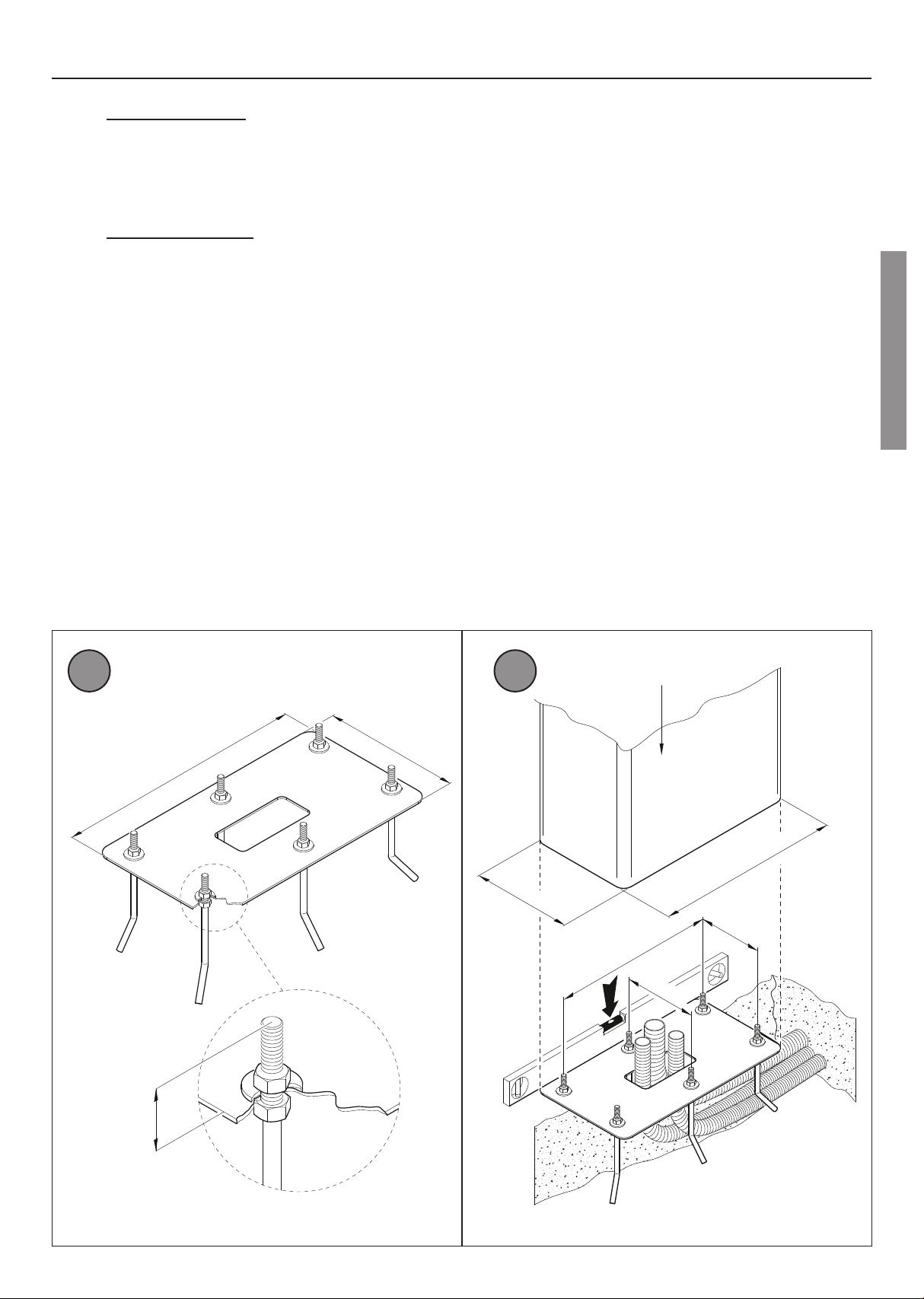
11.2 Installing base plate
• The illustrations herein are indicative only. The space necessary for fastening the automation system and the accessories may vary depending on the overall dimensions
of the installation. The installer is responsible for determining the most suitable solution.
• Excavate a foundation pit measuring 1,5 m x 1 m x 0,5 m and fill with concrete reinforced with steel mesh.
• Fasten the 6 anchor ties to the plate (fig. 1). Note: the bottom nut must be tightened to the end of the thread on the screw so that the length Z is at least 40 mm.
• Sink the base plate with the anchors in the centre of the foundation pit, so that the surface is flush with the concrete and perfectly level. The corrugated cable conduits
must protrude by a few centimetres from the centre of the plate (fig. 2).
• Installation on existing surfaces. Place the base plate on the surface and trace the positions of the fastener points. Drill the surface and insert 6 adequately sized
expansion anchor bolts (purchased separately).
COD. KT244
492
Z≥40
270
429
166
492
270
190
BIONIK8
26
EN
34
56
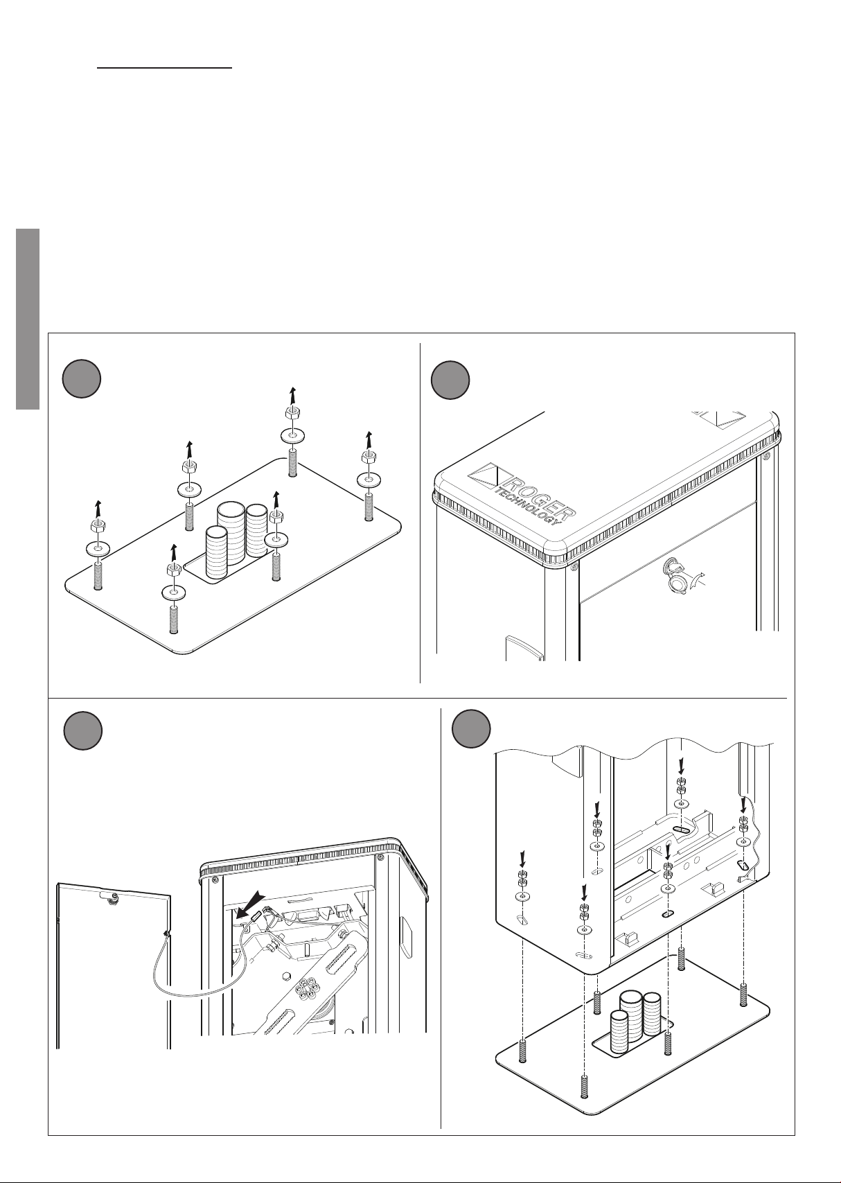
11.3 Installing the barrier
NOTE: the barrier is configured by default for installation on the right hand side (viewed from inspection hatch side).
• Undo and remove the washers and nuts from the anchors on the base plate (fig. 3).
• Open the inspection hatch, turning the key clockwise by 90° (fig. 4).
• Remove the inspection hatch (fig. 5).
• Place the cabinet on the plate. The anchors on the base plate must fit through the six slots.
• Fit the washers and nuts removed previously. Move the cabinet as necessary in the slots to adjust the position of the barrier correctly. Tighten the nuts securely (fig. 6).
90°

27
EN
7
11.4 Selecting direction of aperture
BIONIK barriers are configured by default for installation on the
right hand side (seen from the inspection hatch side).
Whenever corrective actions are carried out, pay the utmost
attention when releasing,locking or moving the internal mechanical
parts. These operations could be hazardous for the installer.
For LEFT hand installations:
1. Unlock the barrier (see chapter 23).
2. Turn the linkage lever as shown in fig. 8.
3. Move the mechanical stop (see chapter 14).
4. Lock the barrier (see chapter 23).
INSTALLATION ON
THE RIGHT
INSTALLATION OF
THE LEFT
8BARRIER INSTALLED ON THE RIGHT (SEEN FROM THE INSPECTION HATCH SIDE) AND THE BOOM
OPENING/CLOSURE GATE ON THE LEFT
BARRIER INSTALLED ON THE LEFT (SEEN FROM THE INSPECTION HATCH SIDE) AND THE BOOM
OPENING/CLOSURE GATE ON THE RIGHT

28
EN
10
9
12 INSTALLING THE BOOM
IMPORTANT: The BIONIK8 barrier is supplied with two 4.1 m booms (D1 and D2).
WARNING!: to avoid damaging the surface of the components, it is recommended to place them on a stable and soft surface.
• Unlock the barrier (see chapter 23).
• Turn the linkage lever into the position necessary for installing the boom horizontally.
• Lock the barrier.
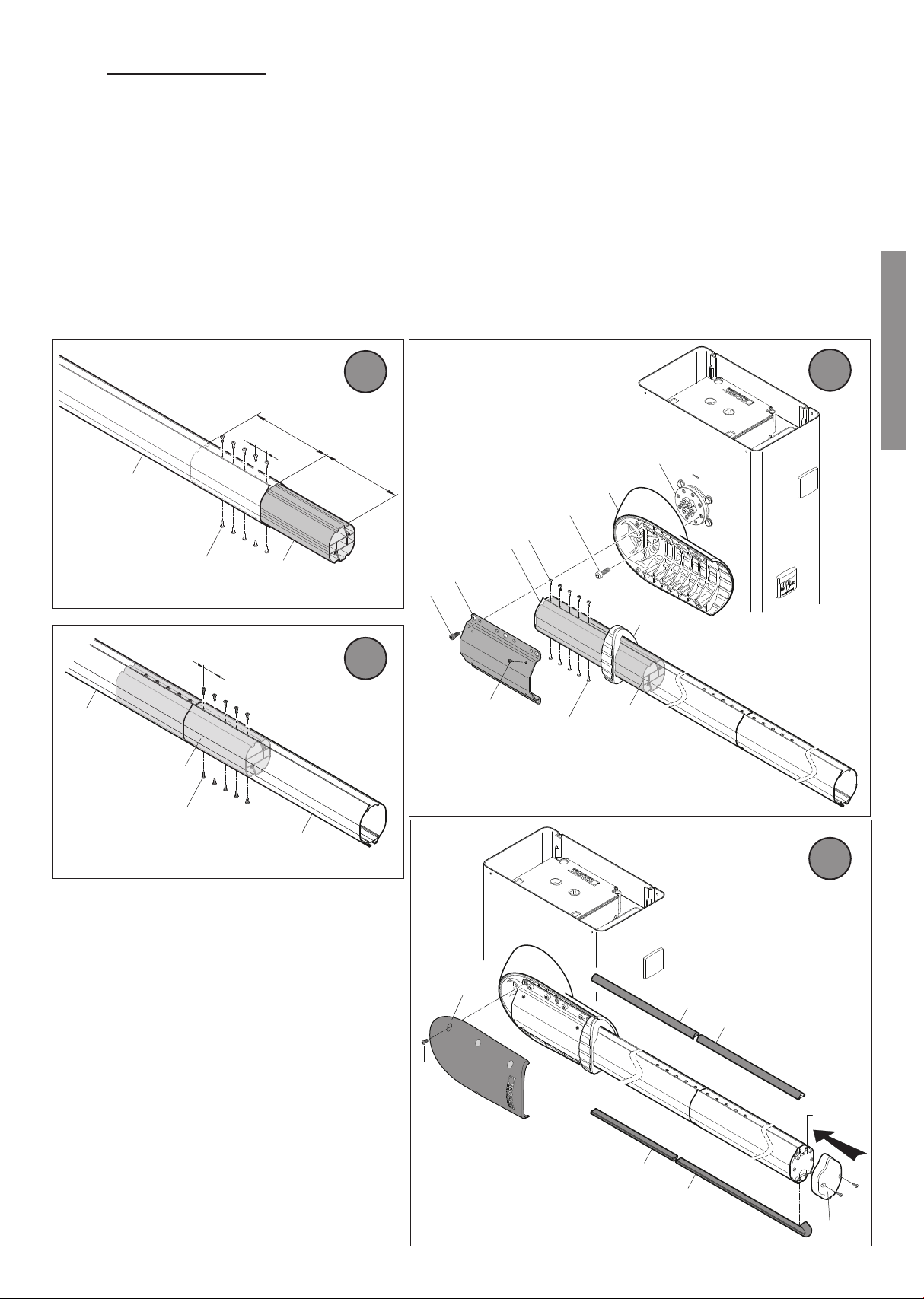
12.1 D1 boom preparation (fig. 9)
• Remove the plug Q1 and the end flange R1. These two parts will NOT be used again.
• Remove the led cover N1 and shorten it by 285 mm from the side where it is fastened to the boom support.
• Remove the protective rubber P1 and shorten it by 285 mm from the side where it is fastened to the boom support.
• Cut the excessive protective rubber at the opposite end as well.
12.2 D2 boom preparation (fig. 10)
• Remove the plug Q2 and the end flange R2.
• Remove the led cover N2 and the protective rubber P2. CAUTION: these two components should NOT be cut.
285
P1
D1
Q1
R1
N1
285
P2
Q2
R2
D2
N2
29
EN
11
12
13
14
12.3 Installation procedure
1. Insert the connector M1 on the boom D1 by half of its length (375 mm), fig. 11.
2. Fasten the boom to the connector using the 10 self-drilling screws [L] included, 5 above and 5 under, along the boom axis, at a distance of 60 mm apart, fig. 11.
3. (Fig. 12) Insert the boom D2 on the other half of the connector and fasten it according to the description above.
4. In this way, the boom will have a length of 8.2 m (fig. 12).
5. Fasten the boom support base [A] to the flange [C] with the 8 M12x30 zinc coated screws [B] and tighten them firmly (fig. 13).
6. Insert the connector M2 completely inside the boom.
7. Fasten the boom to the connector M2 with the 10 self-drilling screws [L] included, 5 above and 5 under, along the boom axis, at a distance of 60 mm apart, fig. 13.
8. Insert the finishing collar [I] on the boom.
9. Insert the boom in its seat on the support [A].
10. Fit the steel bracket [F] and screw the 8 M10x20 zinc coated screws [E] on the boom support [A] and tighten them firmly.
11. Fasten the bracket [F] with 4 self-drilling screws [L] and tighten them firmly.
12. Insert the led covers on the boom, first the N1 and then the N2 and then the protective rubbers, first the P1 and then the P2 (fig. 14).
13. Lastly, fit the aluminium cover [G] and fasten it with the 6 M8 stainless steel screws [H], included.
14. Refit the end flange R2 and the plug Q2 fastening them with the two screws included.
375
60
375
M1
L x10
D1
C
B
D1
F
E
A
M2
L x4
L x5
I
L x5
60
M1
L x10
D2
D1
G
H
N1 N2
P1
P2
Q2
R2
30
EN
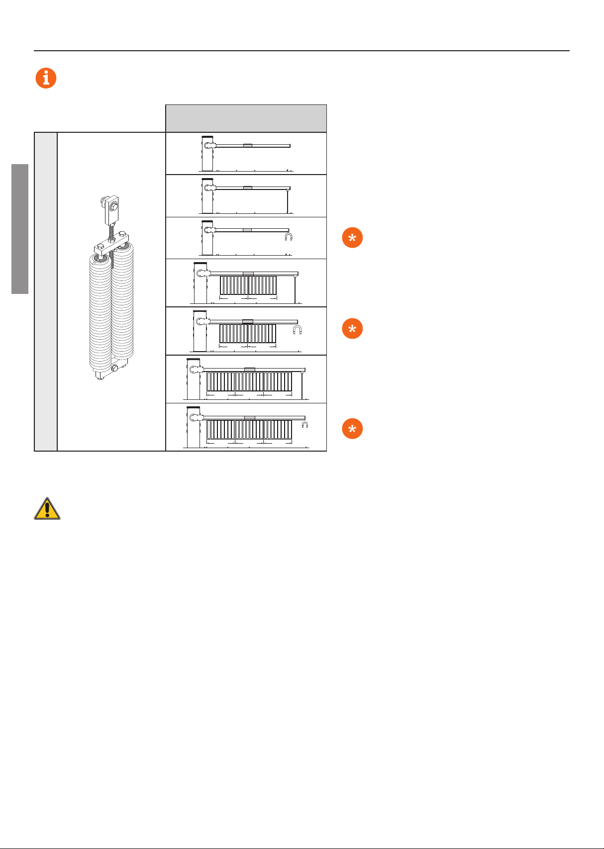
13 INSTALLING AND ADJUSTING THE SPRING
BI/008
with boom up to 8 m
SP/85/AS/02
2 m 2 m
2 m 2 m
2 m 2 m 2 m
2 m 2 m 2 m
For choosing the most suitable configuration, the booms are understood as complete with shock-resistant
rubber and LED strips.
The adjustable fixed end rest with
integrated magnet
BAFS/05 must be used.
The adjustable fixed end rest with
integrated magnet
BAFS/05 must be used.
The adjustable fixed end rest with
integrated magnet
BAFS/05 must be used.
WARNING! For booms of 4 m or more, it is mandatory to use the BAFS fixed end rest or the
BAMS hinged end rest.

31
EN
13.1 Installation and adjustment of the balancing unit
• The balancing unit is composed of a linkage lever, a slider [CU] and a spring unit.
• The linkage lever has two 4 mm pitch toothed windows, on which the [CU] slide will be fit.
• On one of the holes on the slider [CU] the SPRING SET SP/85/AS/02 will be fit.
• The supplied sliders are of two types CU1 and CU2 and can be distinguished by the identifying marks (see *and **). The two types of sliders allow millimetre adjustment
of the spring travel, since the spacing between the holes is different (26-24 mm), see details in fig. 15 and 16.
• Fit the most appropriate slider CU for a correct balancing of the boom.
13.2 Slider selection
• The correct position of the slider is determined by the boom weight: the heavier the boom is (weight determined by the totality of the accessories installed), the
more to the outside the slider should be installed.
• Reversing the insertion direction of the slider, rotating it by 180°, the hole spacing value is modified in relation to the linkage lever centre, see fig. 15 and 16
(e.g. 135, 136, 137, 138 mm values).
• To decrease the travel (extension) of the spring, move the slider CU inward by one pitch in the linkage lever and check the tensioning of the springs.
• Each pitch reduces the travel value by 4 mm..
26
*
24
*
*
SLIDER 1 - CU1
Example 1 Example 1
Example 2 Example 2
SLIDER 2 - CU2
136
*
138
*
137
*
*
135
*
*
15 16
180°
*
180°
*
*

32
EN
13.3 Spring unit installation
1. Unlock the barrier (see chapter 23) and move the boom into the completely open vertical position.
2. Fasten the spring unit SP/85/AS/02 to the linkage lever using the screws included (fig. 17), according to the opening direction and in the position that allows the
correct movement of the barrier. The internal roller bearing [S] is composed of 3 modular elements which, if incorrectly assembled, inhibit the correct operation of the
barrier.
CAUTION: using the slider hole that is the farthest from the linkage lever centre, during barrier operation, the springs will be more tensioned, while, vice versa, when using
the slider hole that is the closest to the linkage lever centre, the springs will be less tensioned.
3. Fasten the springs to the fixed structure (fig. 18) on the steel cross bar of the barrier, using the screws included. The heavier the boom is (totality of the accessories
installed), the more to the outside the springs should be installed (hole A).
4. Check the correct operation of the balancing system.
• Lift the boom manually to an angle of 45° and let go. If the boom rises or falls, try another position of the slider CU1. Whenever this is not sufficient, the slider can be
rotated by 180°, to change the 2 mm holes pitch (fig. 15 - values 136 and 138).
• To obtain millimetre precision, replace CU1 with the CU2 slider included (fig. 16 - values 135 and 137).
5. Grease the points indicated in fig. 17 and 18 with LITHIUM grease (EP LITHIUM). Available upon request, article RS/GR1/100: 100 g can of lithium grease.
Lithium
Li LUBRIFICARE!
LUBRICATE!
A
B
C
17
18
Lithium
Li
LUBRIFICARE!
LUBRICATE!
S
S
Lato Esterno
External side
33
EN
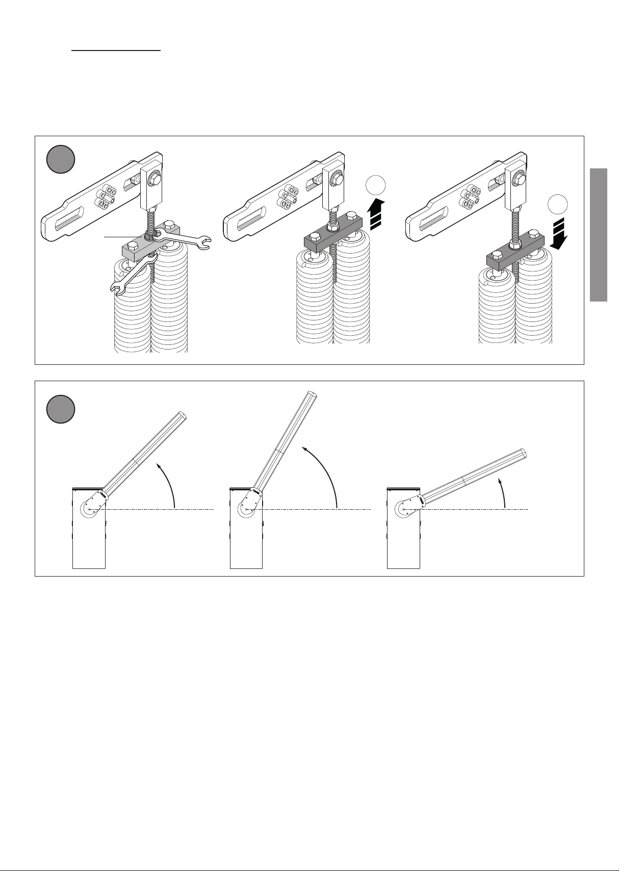
13.4 Spring adjustment
1. Adjust the spring tensioning by loosening the nuts [A] as indicated in fig. 19.
2. By moving upward the fastening cross bar [B], the spring tensioning increases; vice versa, by moving it downward, the tensioning decreases.
3. Lift the boom manually to an angle of 45° and let go. If the boom rises, reduce the spring tension. If the boom falls, increase the spring tension (fig. 20).
4. Once the spring tension is correct, tighten the lock nuts securely.
45°
>45°
<45°
A1
A2
B
+
-
19
20
34
EN
14 ADJUSTING THE
MECHANICAL STOP
Figure 21 shows the mechanical stop on a barrier installed on the
RIGHT hand side. For barriers installed on the LEFT, perform the
mirror images of the procedures illustrated.
• Unlock the barrier (see chapter 23).
• Set the completely open AP and completely closed CH
positions by adjusting the relative mechanical stops.
• Lock the barrier (see chapter 23).
AP
CH
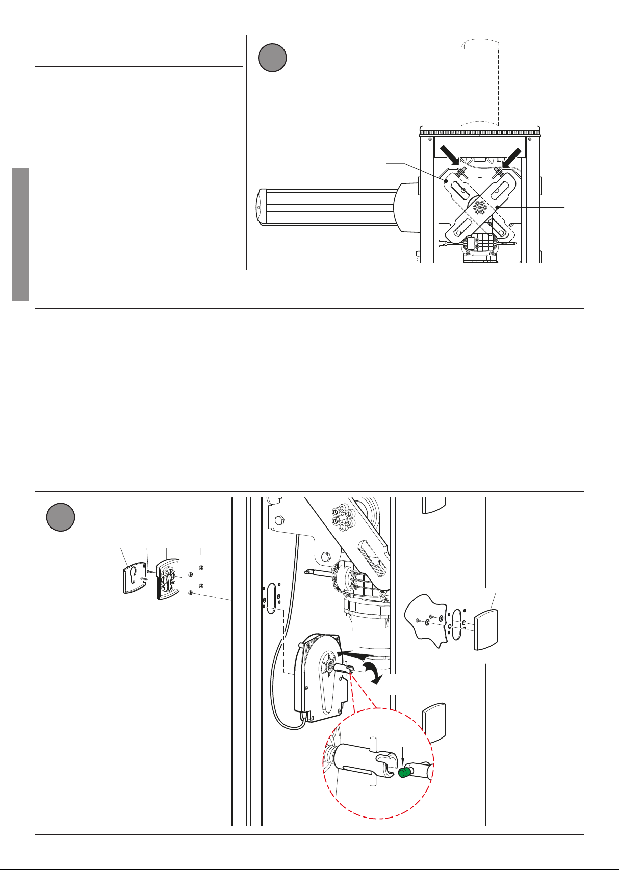
15 INSTALLING THE LOCK RELEASE SYSTEM
The lock release system is already installed in the factory on one of the two side of the barrier.
If it is necessary to install the system on the opposite side:
• Open the inspection hatch.
• Remove the screws fastening the plastic cover [A].
• Remove the escutcheon plate [B] of the lock release system, prising the lateral clips open to detach.
• Undo the two self-tapping screws [C] and remove the aluminium front panel [D].
• Undo the four M5 nuts [E].
• Push the steel connector [F] outwards to compress the spring and rotate by 45°.
• Detach the lock release system and install on the opposite side, taking care not to damage the safety cable.
NOTE: two coloured caps (red and green) are fitted to check that the lock release system is installed correctly, regardless of which side it is fitted on.
When the barrier is locked, the green cap must face towards the inspection hatch (installer view). If not, the lock release system is installed incorrectly.
• Tighten the nuts [E].
• Fit the aluminium front panel [D] and fasten with the screws [C].
• Fasten the escutcheon plate [B] on the lock release system.
• Fit the plastic cover [A] on the opposite side.
A
F
EDCB
VERDE
GREEN
G
21
22
35
EN
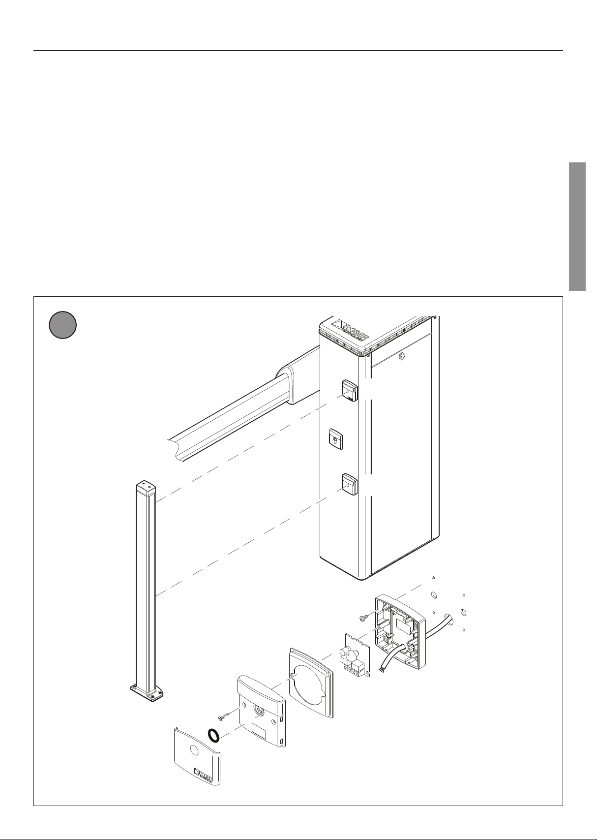
16 CONNECTING PHOTOCELLS
G90/F4ES photocells may be installed on both sides of the barrier at two different heights: (50 cm or 100 cm).
• Disconnect from mains electricity and from battery power (if applicable).
• Open the inspection hatch, turning the key clockwise by 90°.
• Undo the four screws fastening the head.
• Remove the head after disconnecting the flashing light cables.
• Open the cover of the CTRL control unit.
• Undo the two screws fastening the plastic cover of the photocell housing from the inside.
• Fasten the G90/F4ES photocells to the barrier.
• Route the connector cables upwards, taking care not to interfere with the movements of the automation system, and push them through one of the openings on the
control unit box.
• Connect the photocells cables to the specific terminals as indicated in the installation manual for the CTRL controller.
• See the CTRL control unit manual for instructions on setting the photocells.
• Close the control unit cover correctly, ensuring that it is watertight.
• Refit the barrier head.
• Close the inspection hatch, turning the key anticlockwise by 90°.
• Tighten the four screws to the head.
RX
TX
TX
RX
23

36
EN
17 ELECTRICAL CONNECTIONS
All electrical connections must be made with the unit disconnected from mains
power and, if applicable, battery power.
See the CTRL controller manual for instructions on making connections and
programming.
Before connecting to electrical power, ensure that the mains power specifications
on the identification plate match the mains power supply used.
A switch or an omnipolar cut-off switch with a contact opening of at least 3 mm
must be installed on the mains power line.
Ensure that an adequate residual current circuit breaker and a suitable overcurrent
cut-out are installed ahead of the electrical installation.
Use a 3x2.5 mm2double insulated cable for the mains power line.
Feed the cable on the left hand side of the barrier through the openings on the left
hand side of the controller casing and connect it to the terminals L (brown), N (blue)
and (yellow/green) inside the automation unit.
Fasten the power cable with the cable grips included.
At least 50 mm of the connector cable conduit must protrude from the holes in the
base plate and into the automation unit.
Ensure that there are no sharp edges which could damage the power cable.
24
25
A
B
C
D
E
OFF
F
G
G
Z x4
BLACK
RED
F1
F2
PROG TEST
+
-
BATTERY (+)
RECEIVER CARD
BATTERY CHARGER
SEC2
SEC1
BATTERY (-)
123456
ROSSO
RED
BLU/BLUE
NERO/BLACK (-) (+)
18 INSTALLING THE BATTERY KIT (OPTIONAL)
1. Disconnect the mains power.
2. Unscrew the four screws [Z] and remove the head [A] (if applicable).
3. Lift the cable grommet [B] and disconnect the connector [C].
4. Open the transparent control unit cover [D].
5. Switch the control unit switch to the OFF position [E].
6. Lift the control unit and insert the batteries in their housing [F].
7. Connect the red, black and blue wires to the batteries (see detailed view)
8. Connect the batteries to the +BATTERY terminal (red wire) and -BATTERY terminal (black wire).
9. Insert the battery charge board BI/BCHP in the plug-in connector [G].
10. Reposition the control unit.
11. Switch the control unit switch to the ON position [E].
12. Reposition the transparent control unit cover [D].
13. Reconnect the connector [C] and close the cable grommet [B].
14. Close the head [A] and tighten the four front screws [Z].
15. Reconnect the mains power.
L
N

37
EN
19 INSTALLING THE BI/BLED/8 LED FLASHING LIGHT (fig. 26-27)
The BI/BLED/8 flashing lamp unit is factory supplied already pre-installed in the head [A], packaged separately inside the BIONIK package.
1. Insert the connector [B] in the LIGHT terminal of the control unit.
2. Refer to the control unit manual for the flashing lamp unit settings.
3. Fasten the cable grommet [C], making sure it is positioned correctly.
4. Position the head [A] on the barrier.
5. Tighten the four fastening screws [Z].
In case of replacement:
1. Disconnect the mains and battery power supplies (if applicable).
2. Unscrew the four screws [Z] that fasten the head [A] to the barrier.
3. Lift the cable grommet [C].
4. Disconnect the connector [B].
5. Remove and overturn the head [A].
6. Remove the BI/BLED/8 flashing lamp unit [D] from the diffuser.
7. Insert the new LED circuit in the diffuser, paying attention to the installation direction (fig. 27).
8. Insert the connector [B] in the LIGHT terminal of the control unit CTRL.
9. Refer to the control unit manual for the flashing lamp unit settings.
10. Fasten the cable grommet [C], making sure it is positioned correctly.
11. Reposition the head [A] on the barrier.
12. Tighten the four fastening screws [Z].
13. Reconnect the mains and battery power supplies (if applicable).
B
C
x4
Z
A
C
D
D
D
A
LED LIGHT
26
27

38
EN
FIG. 1
In some situations, such as in the event of a power outage or scheduled or extraordinary maintenance, it is necessary to release the automation.
The operation of the release of the automation must be carried out when the boom is is stopped in the closed position (horizontal).
Moreover, ensure that at the time of release, no person, animal, item or vehicle is passing by or stopped within range of automation.
RELEASE AND MANUAL OPERATION
Insert the key included into the lock and turn it anticlockwise by 360° making 2 complete turns, as indicated in fig. 1.
Move the boom manually.
RESTORING AUTOMATIC OPERATION
To lock the barrier again, turn the key clockwise by 360° making 2 complete turns, as indicated in fig. 2.
Remove the key and give to the user.
FIG. 2
Whenever corrective actions are carried out, pay the utmost attention when releasing, locking or moving the internal mechanical
parts. These operations could be hazardous for the installer.
20 MAINTENANCE
N.B.: Only use original spare parts when repairing or replacing products.
The installer must provide the user with complete instruction for using the motorised
door or gate in automatic, manual and emergency modes, and must hand the
operating instructions to the user of the installation upon completion.
The installer must compile the maintenance log book, in which all scheduled and
unscheduled maintenance operations performed must be indicated.
• The installation must be subject to regular maintenance. We recommend
servicing at least once every 6 months.
• Disconnect from mains electricity and from battery power (if applicable) to avoid
the risk of accident or injury.
• Check the tightness of all the fastener screws and nuts.
• Clean the photocell lenses with a cloth moistened slightly with water. Do not
use solvents or other chemical products, as these may damage the electronic
components.
• Clean and lubricate the pivot points with lithium based grease (EP LITIO).
• Check the electrical connections.
• Check that the manual lock release system works.
• Check that the boom is balanced correctly as indicated in chapter 13.
• Check that there are now plants within the radius of action of the boom which
could interfere with the photocells or with the movements of the boom itself.
Reconnect to mains power.
• Check that the safety devices and all the control functions work correctly.
• Check that the obstacle detection function works correctly.
• Check that there is no risk of the boom accidentally lifting persons or objects.
• Check that the force limiting function prevent potentially dangerous situations in
compliance with the standard EN 12445.
21 DISPOSAL
This product may only be uninstalled by qualified technical personnel,
following suitable procedures for removing the product correctly and
safely.
This product consists of numerous different materials.
Some of these materials may be recycled, while others must be
disposed of correctly at the specific recycling or waste management
facilities indicated by local legislation applicable for this category of product.
Do not dispose of this product as domestic refuse.
Observe local legislation for differentiated refuse collection, or hand the product
over to the vendor when purchasing an equivalent new product.
Local legislation may envisage severe fines for the incorrect disposal of this product.
Warning! some parts of this product may contain substances that are harmful to
the environment or dangerous and which may cause damage to the environment or
health risks if disposed of incorrectly.
22 ADDITIONAL INFORMATION AND
CONTACT
ROGER TECHNOLOGY is the exclusive proprietor holder of all rights regarding this
publication.
ROGER TECHNOLOGY reserves the right to implement any modifications without
prior notification. Copying, scanning or any alterations to this document are
prohibited without express prior authorised from by ROGER TECHNOLOGY.
ROGER TECHNOLOGY CUSTOMER SERVICE:
business hours: Monday to Friday
08:00 to 12:00 - 13:30 to 17:30
Telephone no: +39 041 5937023
E-mail: service@rogertechnology.it
Skype: service_ rogertechnology
2x360° 2x360°
23 RELEASE AND LOCK PROCEDURE
Other manuals for BIONIK8
1
Table of contents
Other Roger Technology Other manuals


Popular Other manuals by other brands


Sicor
Sicor MR17 Operation and maintenance manual

PROAIM
PROAIM CINEMA DL-BRIO-00 instruction manual

Orbinox
Orbinox ALUMINUM STOP LOG SA Installation, operation and maintenance manual

Promate
Promate Lumino user guide

Advanticsys
Advanticsys MPC-143 user manual

Nilfisk-Advance
Nilfisk-Advance Hybrid Typhoon Directions for use


