PR302EN.doc
10
Optical (LED) signalization
Controller offer three LEDs marked as ON/OFF, OPEN and SYSTEM. An ON/OFF led is a bicolor type and may be set to green or red.
When set to green it signalize that controller is in ON mode, when is set to red it signalize that controller is in OFF mode. Led OPEN (green)
signalize that relay output is activated what usually mean that door lock is energized. A SYSTEM led (amber) is activated for a moment
each time a card or PIN is read, it pulses continuously after SWITCHER FULL, SWITCHER LOCAL or MASTER identifier is used and
controller wait for next part of command which will change ON/OFF mode of controller.
Note: When all three leds are blinking and a short acoustic beep is generated periodically it means that controller memory is corrupt and
MEMORY RESET is required.
Acoustic signalization
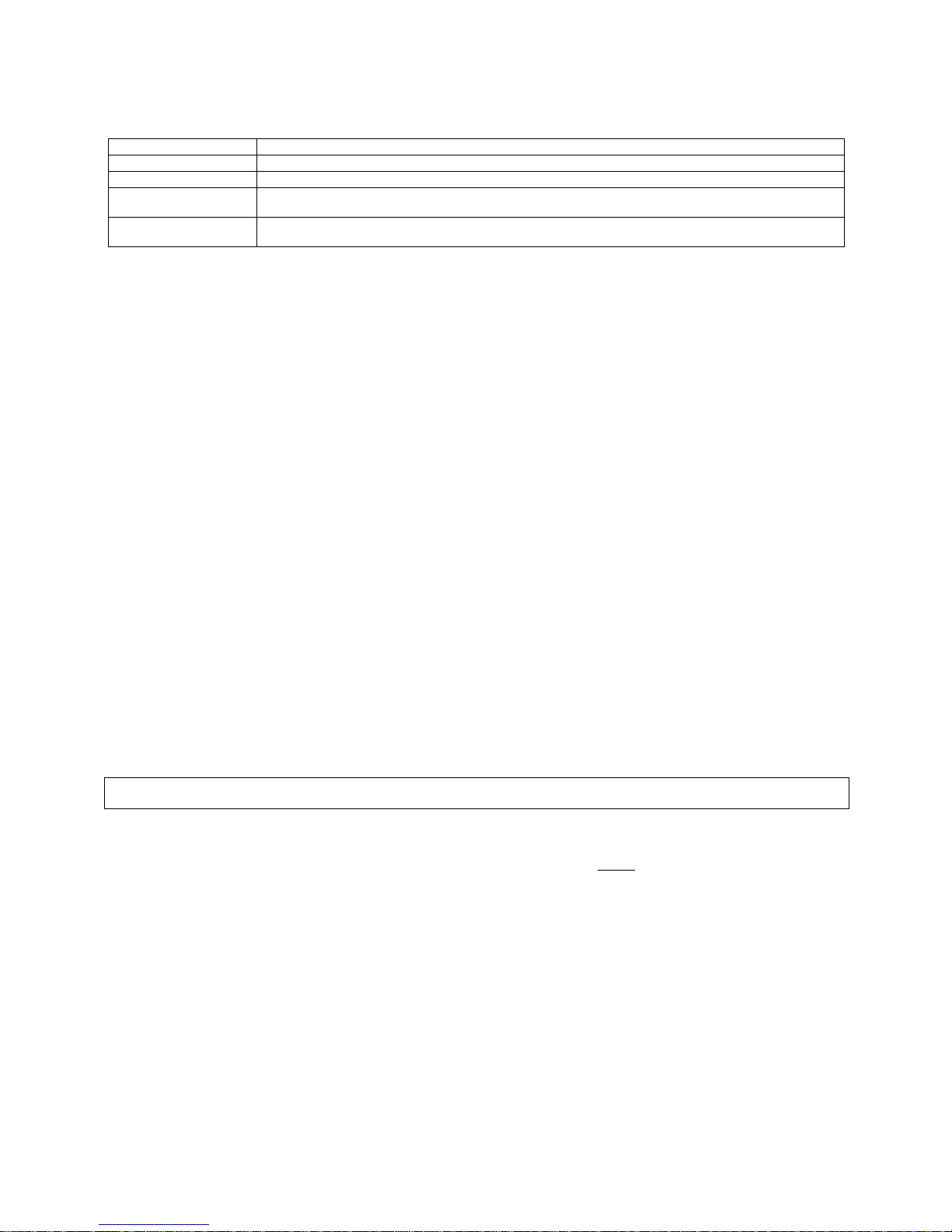
The following acoustic signals can be generated by controller:
Signal Description
One beep Card read or Key pressed.
Three beeps OK signal, command or operation finished successfully.
Two beeps OK signal, controller wait for next part of command.
One long signal Card or PIN unknown (nor registered in controller).
Two long signals Card or PIN without authorization for entry (identifier registered in
controller’s memory but actually have no authorization for access).
Long signal repeated continuously Memory contents corrupted, controller should be reprogrammed.
Installation
Locate the controller in a dry area, all electrical connections must be made with power supply off. Once wiring is complete, power up the
control panel. The controller should be mounted using four mounting screws. Originally the new controller is delivered with preprogrammed
MASTER Card (included in carton box), preprogrammed MASTER PIN code (1234) and ID address set to “00“.
!Avoid installing unit near big metal elements or on metal surfaces, this can significantly reduce reading range.
!When installing unit on metal surface use optional non-metal spacer (10mm thick or more) between device and metal surface.
!When controller and external terminal are supplied from another power source, both minuses (terminal’s and controller’s) must be
connected together.
!Roger recommend to ground power supply minus.
!Controller should not cause interferences to other equipment, however other devices can interfere with controller reader, avoid
locating controller close (<0.5m) to another reader or computer monitor, when an essential reading range reduction is observed
try to relocate units.
!PR302 can not be mounted in external location, it hasn’t any protection against moisture, rain or cold, only indoor location are
acceptable.
Note: You must complete all wiring before applying DC supply to controller.
Connection Terminals Descriptions
Controller Supply, terminals: +12V -
PR302 should be supplied from 10.0 to 16.0V DC current source equipped with reserve battery. The average current consumption is about
80 mA and may increase up to 130 mA when relay output is activated. Care must be taken when selecting cable diameter for supply,
installer must carefully calculate the maximum voltage dropout on supply lines which should not reach 1V in worst case, this is very
important especially when electric lock is supplied from the same supply source as controller and other electronic equipment. It is preferable
to use separate supply sources for electronic equipment and electric locks. When both elements are supplied from the same power source
they should be wired with separate cables. Usually the access control system is distributed on relatively large areas, this requires distributed
supply system with many supply sources located as close as possible to supplied equipment. It is recommended to use modern supply units
which are equipped with alarm output lines (AC Lost output and Low Battery output e.g. PS20). Such a lines should be connected to
controller inputs for continuous monitoring. Generally controller accepts linear and switched supplies types, occasionally poor quality of
switched supplies may generate some interferences on supply lines which may result in reduced card reading range, this may happen
especially when long range readers are installed, some brands of such readers are especially very sensitive to poor quality of supply.
Input lines, terminals: IN1, IN2 and IN3
Each controller input (IN1, IN2 and IN3) have the identical electrical structure. All inputs are NO/NC type with 5,6 kΩresistor pulled up to
supply plus. During setup process installer may configure each input independent as NO or NC. The NO type input is triggered when
connecting it to supply minus. The NC input normally must be shorted with supply minus, when disconnecting it from supply minus it became
triggered. Controller ignore triggering impulses if they are shorter then 200 ms and accept signals that are longer then 500 ms. Detection of
signals between 200 and 500 ms is not guaranteed. Each controller input can be programmed to different function and may be under control
of time schedule.
RS485 communication interface, terminals: A, B and SHLD
The RS485 interface consist from two signal lines (A and B) and optional cable shield terminal (SHLD). Installer may use arbitrary
communication bus topology (star, three or any combination of both), no terminating resistors are required. In most cases communication
runs satisfactory on almost each types of cables (twisted/untwisted, shielded/unshielded) but it is not guaranteed in each case. Generally
unshielded, twisted type cables are preferred and guarantee best performance of communication. Each communication line (A and B) is
protected from voltage surges and from supply minus and plus. RS485 standard of transmission guarantee up to 1200 meters
communication distance with high immunity against interferences. When longer communication distances are required the UT-3 or UT-4
interfaces might be used. The one pair of UT-3 interfaces extend communication distance by 1200m, the UT-4 enables communication
trough computer network (LAN or WAN) witch utilize TCP/IP protocol.