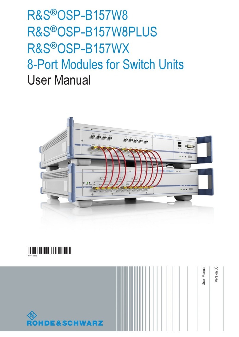
Rohde & Schwarz R&S RSC User manual

R&S®RSC
Step Attenuator
User Manual
1313891002
Version 05
(==ç:2)

This manual describes the R&S®RSC and its instrument variants:
●R&S®RSC base unit without attenuator 1313.8004.02
●R&S®RSC attenuator up to 6 GHz from 0 dB to 139 dB in 1 dB steps
1313.8004.03/13
●R&S®RSC attenuator up to 6 GHz from 0 dB to 139 dB in 0.1 dB steps
1313.8004.04/14
●R&S®RSC attenuator up to 18 GHz from 0 dB to 115 dB in 5 dB steps
1313.8004.05/15
●External attenuator up to 40 GHz and an attenuation range from 0 dB to 75 dB
in 5 dB steps (R&S RSCZ405 1313.9952.02).
●External attenuator up to 67 GHz and an attenuation range from 0 dB to 75 dB
in 5 dB steps (R&S RSCZ675 1314.0065.02).
The software contained in this product uses several valuable open source software packages. For infor-
mation, see the "Open Source Acknowledgment" on the user documentation CD-ROM (included in deliv-
ery).
Rohde & Schwarz would like to thank the open source community for their valuable contribution to embed-
ded computing.
© 2020 Rohde & Schwarz GmbH & Co. KG
Mühldorfstr. 15, 81671 München, Germany
Phone: +49 89 41 29 - 0
E-mail: [email protected]
Internet: www.rohde-schwarz.com
Subject to change – Data without tolerance limits is not binding.
R&S® is a registered trademark of Rohde & Schwarz GmbH & Co. KG.
Trade names are trademarks of the owners.
1313.8910.02 | Version 05 | R&S®RSC
The following abbreviation is used in this manual: R&S®RSC is abbreviated as R&S RSC

Contents
R&S®RSC
3User Manual 1313.8910.02 ─ 05
Contents
1 Documentation overview...................................................... 5
2 Introduction............................................................................7
3 Putting the instrument into operation................................. 9
3.1 Explanation of the front and rear views..............................................9
3.2 Preparing the instrument................................................................... 12
3.3 Function check....................................................................................17
3.4 Default settings................................................................................... 18
3.5 Linux operating system......................................................................18
3.6 Connecting external devices............................................................. 19
3.7 Configuration using LXI..................................................................... 22
3.8 Configuration of the GPIB bus (IEC 625 / IEEE 488)........................29
4 Manual operation................................................................. 31
4.1 Entering parameters........................................................................... 31
4.2 Display................................................................................................. 32
4.3 Help system – [HELP] key..................................................................32
4.4 File functions.......................................................................................33
5 Instrument functions........................................................... 35
5.1 Setting the attenuation....................................................................... 35
5.2 Varying the attenuation...................................................................... 35
5.3 Setting the frequency......................................................................... 35
5.4 Turning the correction mode On/Off................................................. 36
5.5 Display of the attenuation deviation................................................. 37
5.6 Switching to external attenuators..................................................... 40
5.7 Cascading external attenuators........................................................ 40

Contents
R&S®RSC
4User Manual 1313.8910.02 ─ 05
6 Application........................................................................... 43
6.1 Effect of reflection on the attenuation deviation............................. 43
6.2 Disturbance voltages..........................................................................43
7 Remote control.................................................................... 47
7.1 Basic information on remote control................................................ 47
7.2 Remote control – commands.............................................................57
8 Maintenance......................................................................... 75
9 Contacting customer support............................................ 77
Annex....................................................................................79
A Instrument interfaces.......................................................... 79
A.1 GPIB bus (IEC 625 / IEEE 488)........................................................... 79
A.2 Ethernet interface (LAN).....................................................................83
List of commands................................................................ 87
Index..................................................................................... 89

Documentation overview
R&S®RSC
5User Manual 1313.8910.02 ─ 05
1 Documentation overview
This section provides an overview of the R&S RSC user documentation. Unless
specified otherwise, you find the documents at:
https://www.rohde-schwarz.com/manual/RSC
User manual
The user manual is supplied with the delivery in printed form. It contains descrip-
tions for all instrument functions and for remote control of the instrument. In addi-
tion, it contains notes on preventative maintenance for the R&S RSC and on trou-
bleshooting based on the warnings and error messages that the instrument emits.
The user manual is also included on the documentation CD-ROM that is supplied
with the delivery.
HTML help
The context-sensitive help is installed on the R&S RSC in its standard configura-
tion. It supports you in operating the R&S RSC and its options, both manually and
remote via control.
A modern HTML5 variant is available on the internet and supplied on the docu-
mentation CD-ROM.
Service manual
Describes the performance test for checking the rated specifications, module
replacement and repair, firmware update, troubleshooting and fault elimination,
and contains mechanical drawings and spare part lists.
The service manual is available for registered users on the global
Rohde & Schwarz information system (GLORIS):
See https://gloris.rohde-schwarz.com.
Instrument security procedures
Deals with security issues when working with the R&S RSC in secure areas.
It is available for download on the internet and also included on the documenta-
tion CD-ROM.

Documentation overview
R&S®RSC
6User Manual 1313.8910.02 ─ 05
Data sheets and brochures
The data sheet contains the technical specifications of the R&S RSC. It also lists
the firmware applications and their order numbers, and optional accessories.
The brochure provides an overview of the instrument and deals with the specific
characteristics.
See https://www.rohde-schwarz.com/brochure-datasheet/RSC.
Open source acknowledgment (OSA)
The R&S RSC firmware makes use of several valuable open source software
packages. An open-source acknowledgment document provides verbatim license
texts of the used open source software.
It is included on the documentation CD-ROM supplied with the delivery.

Introduction
R&S®RSC
7User Manual 1313.8910.02 ─ 05
2 Introduction
The R&S RSC attenuator is a fast and accurate instrument for setting precisely
defined attenuation values. Depending on the specific model, attenuation can be
set at a value between 0 dB and 139.9 dB in the frequency range up to 18 GHz.
In addition, external attenuators are available, which can be remotely controlled
with the base unit.
The following models are available:
●Base unit: Instrument without internal attenuator.
●Attenuator up to 6 GHz and an attenuation range from 0 dB to 139 dB in 1 dB
steps.
●Attenuator up to 6 GHz and an attenuation range from 0 dB to 139.9 dB in
0.1 dB steps.
●Attenuator up to 18 GHz and an attenuation range from 0 dB to 115 dB in
5 dB steps.
●External attenuator up to 40 GHz and an attenuation range from 0 dB to 75 dB
in 5 dB steps.
●External attenuator up to 67 GHz and an attenuation range from 0 dB to 75 dB
in 5 dB steps.
With all models, it is possible to connect and control up to 4 external attenuators.

Introduction
R&S®RSC
8User Manual 1313.8910.02 ─ 05

Putting the instrument into operation
R&S®RSC
9User Manual 1313.8910.02 ─ 05
3 Putting the instrument into operation
The R&S RSC attenuator is available in different models. You can equip the base
unit with an internal attenuator and/or use it with up to four external attenuators,
see Chapter 2, "Introduction", on page 7. The following description applies to all
models; differences are pointed out explicitly where relevant.
The section below describes how to put the instrument into operation, connect
external instruments and integrate the R&S RSC into a network. General notes
are provided to ensure safety while operating the instrument.
Please note that the general safety notes at the beginning of this manual
also contain information about operating requirements to prevent damage to
the instrument. In addition, the instrument's data sheet can contain further
operating conditions.
3.1 Explanation of the front and rear views
This chapter shows all function keys, control elements and connections on the
front and rear of the R&S RSC.
3.1.1 Front view
The figure below shows the controls and connections on the front of the instru-
ment.
Explanation of the front and rear views

Putting the instrument into operation
R&S®RSC
10User Manual 1313.8910.02 ─ 05
RF port
The two RF ports, "A" and "B", can be used as either an input or output port.
Depending on the specific model, these interfaces are located on either the front
or rear panel.
Possible damage due to overloading
Ensure that the input level does not exceed 30 dBm (corresponds to 7 V or
1 W).
3.1.2 Rear view
This section shows all interfaces on the back of the R&S RSC.
Explanation of the front and rear views

Putting the instrument into operation
R&S®RSC
11User Manual 1313.8910.02 ─ 05
3.1.3 View of the R&S RSC-Zxx
This view shows the external R&S RSC-Zxx attenuator.
Explanation of the front and rear views

Putting the instrument into operation
R&S®RSC
12User Manual 1313.8910.02 ─ 05
3.2 Preparing the instrument
This section covers the basic steps required for setting up the R&S RSC and put-
ting it into operation.
Safety precautions
Be sure to follow the instructions in the sections below to prevent injury to
people or damage to the instrument. Following the instructions is particu-
larly important the first time that you use the instrument. In addition, be sure
to observe the general safety notes at the beginning of this manual.
3.2.1 Unpacking the instrument
The instrument is delivered together with the accessories in a cardboard box.
Proceed as follows to unpack its contents:
1. Remove the instrument from its packaging.
2. Check the shipment for completeness by comparing it with the shipping docu-
ment and the accessory lists for the various items.
3. Remove the protective cover made of corrugated cardboard from the rear of
the instrument.
4. A corrugated cardboard cover protects the front of the instrument; carefully
unthread this cover from its location in the instrument handles and remove it.
5. Check the instrument for any damage. If there is any damage, immediately
contact the shipping company that delivered the instrument. If this case, be
certain that you keep the cardboard box and packing materials.
Packing materials
We recommend that you retain the packaging. Keep the original packing
material to prevent control elements and connectors from being damaged if
the instrument has to be transported or shipped later.
Preparing the instrument

Putting the instrument into operation
R&S®RSC
13User Manual 1313.8910.02 ─ 05
3.2.2 Setting up the instrument
This instrument is designed for indoor use.
Always place the product on a stable, flat and level surface with the bottom of the
product facing down. If the product is designed for different positions, secure the
product so that it cannot fall over.
If the product has foldable feet, always fold the feet completely in or out to ensure
stability. The feet can collapse if they are not folded out completely or if the prod-
uct is moved without lifting it. The foldable feet are designed to carry the weight of
the product, but not an extra load.
If stacking is possible, keep in mind that a stack of products can fall over and
cause injury.
If you mount products in a rack, ensure that the rack has sufficient load capacity
and stability. Observe the specifications of the rack manufacturer. Always install
the products from the bottom shelf to the top shelf so that the rack stands
securely. Secure the product so that it cannot fall off the rack.
Possible damage to the instrument from overheating
Restricted air current or excessively high ambient temperatures can cause
the instrument to overheat.
To ensure sufficient air supply, all fan openings must be clear, and the air-
flow at the vents on the sides of the instrument must not be impeded. The
instrument must be positioned at least 10 cm away from the wall.
The ambient temperature must lie within the range specified in the data
sheet.
Preparing the instrument

Putting the instrument into operation
R&S®RSC
14User Manual 1313.8910.02 ─ 05
Potential damage caused by electrostatic discharge
Electrical discharges can damage components of the instrument or a con-
nected instrument under test.
For this reason, the instrument must only be operated at a workplace that is
protected against electrostatic discharge.
The following methods can be used separately or in combination to protect
against electrostatic discharges:
●Protective wrist strap with a ground conductor
●Conductive floor covering combined with use of a heel grounder
EMI Suppression
To suppress electromagnetic interference (EMI), the instrument can only be
operated when it is closed and all covers are in place. The instrument's
EMC rating is specified on the data sheet.
To prevent influences that cause disturbances, the following conditions
must be adhered to:
●Use suitable double-shielded cables.
●Do not use any USB cables that are longer than 1 m.
●Only use USB devices that maintain the permitted EMC values.
●For the LAN connection, use CAT6 or CAT7 RJ-45 cables (LAN, Ether-
net)
Preparing the instrument

Putting the instrument into operation
R&S®RSC
15User Manual 1313.8910.02 ─ 05
3.2.3 Connecting the R&S RSC to the AC power supply
Possible damage to the instrument
Before you connect the instrument and turn it on, you must ensure observ-
ance of the following points to prevent damage to the instrument:
●The housing covers must be in place, and their screws must be fas-
tened.
●The ventilation openings must be clear; it must be ensured that air can
freely exit at the back of the instrument and at the holes on the sides.
The minimum distance to the wall can, therefore, be at least 10 cm.
●The instrument must be dry.
●The instrument should only be operated in the horizontal position on an
even surface.
●The ambient temperature must be within the range specified in the data
sheet.
●It must be ensured that none of the voltage levels at the inputs exceed
permissible limits.
●Explanation:
Measuring circuits as defined in section 6.7.4 of EN61010-1
Measuring category I is intended for measurements on circuits that are
not connected to the high-voltage current system.
●It must be ensured that the instrument outputs are not overloaded or
incorrectly connected.
When the instrument is connected to the AC supply, it automatically adjusts
to the AC supply voltage (see the labeling for the voltage range). Do not
manually adjust the instrument to a specific voltage or to change the fuse.
Preparing the instrument

Putting the instrument into operation
R&S®RSC
16User Manual 1313.8910.02 ─ 05
3.2.4 Turning the instrument on and starting
1. Use the supplied power cable to connect the R&S RSC to the AC power sup-
ply.
Danger of electric shock
The attenuator complies with the specifications for the EN61010-1 protec-
tive class, which means that it can only be connected to a power outlet that
has a protective contact.
2. Switch the power switch to [I].
The power switch has two positions:
●[0]: The instrument is disconnected from the AC supply.
●[I]: The instrument is receiving power from the AC supply.
3. Press the [POWER] (stand-by) button on the front of the instrument.
Depending on actuation of the POWER (stand-by) button, the instrument is either
in stand-by mode or it is turned on.
After the instrument is turned on, the BIOS version that is installed and the com-
puter characteristics are displayed on the screen for several seconds.
The Linux operating system boots and then starts the instrument's firmware.
While its firmware is loading, the instrument performs a self test.
The R&S RSC loads the instrument's most recent state, if the previous measure-
ment was ended properly. The booting process is complete when the R&S RSC's
Preparing the instrument

Putting the instrument into operation
R&S®RSC
17User Manual 1313.8910.02 ─ 05
standard image appears on the screen. The instrument is now ready for opera-
tion, and it can be operated manually or via remote control.
3.2.5 Switching the instrument off
Possible data loss due to premature switch-off
If, during operation, you switch off the power switch on the back of the
instrument loses its current settings. This is also the case, if you pull out the
power plug before the operating system has powered down properly. In
addition, it is possible that data will be lost and that problems will arise the
next time the instrument is turned on.
Always press the [POWER] (stand-by) button on the front of the instrument
beforehand to shut down the application properly.
To switch the R&S RSC off, proceed as follows:
1. Press the [POWER] (stand-by) button on the front of the instrument.
The instrument switches to stand-by mode, which means that the current con-
figuration is stored. The R&S RSC application is closed, and the Linux operat-
ing system is shut down.
2. To separate the instrument completely from the AC supply, switch the power
switch on the rear of the instrument to "0".
3. Disconnect the power cable at the AC power supply.
3.3 Function check
The R&S RSC automatically monitors the most important instrument functions
when it is turned on.
Function check

Putting the instrument into operation
R&S®RSC
18User Manual 1313.8910.02 ─ 05
3.4 Default settings
To set the instrument to a defined state, press the [PRESET] button on the front
of the instrument.
This function resets all the instrument's settings to the default values, even if a
mode is not currently turned on. The following table shows the most important
parameters and their default settings:
Display Switch to main screen
Main screen Display of the internal attenuator. If no internal attenuator is
installed, the first externally connected attenuator is dis-
played.
Attenuation Max. (including external attenuators)
Frequency Min.
Correction Off
User Cal Off
Abs/Rel Rel
Offset 0 dB
3.5 Linux operating system
Possible impairment of instrument functions
The instrument runs the Linux operating system.
At the factory, the operating system configuration was tuned for ideal sup-
port of the attenuator functions. Change system settings only when the con-
figuration of a connected network deviates from the standard settings.
After the R&S RSC is turned on, the operating system is loaded and the instru-
ment's firmware starts automatically. Access to the operating system is locked. All
required system settings can be defined in the setup menu. The instrument is
equipped with internal flash memory. The flash memory contains the operating
system, the firmware and the stored user data. Data can be transferred via the
Linux operating system

Putting the instrument into operation
R&S®RSC
19User Manual 1313.8910.02 ─ 05
USB port using a USB flash drive. You can use the file manager to access the
USB flash drive.
3.6 Connecting external devices
The R&S RSC is equipped with different interfaces, for example for connecting
external attenuators or USB devices or for connecting to a network. Furthermore,
the instrument is equipped with interfaces for integration into a network, see
Chapter 3.6.3, "Integrating the R&S RSC into a network", on page 20.
3.6.1 Connecting external attenuators
The R&S RSC is equipped with 4 connections on the rear panel for external
attenuators as standard. The sockets are labeled with [EXTERNAL
ATTENUATOR 1…4].
The external attenuator is connected to the R&S RSC's rear panel sockets using
an RSC-Z41 cable. An RSC-Z42 cable with a standard USB plug on one end is
used to connect to a computer.
If an external attenuator is detected, it is initialized automatically. Autodetection
can take a few seconds when connecting for the first time. A USB symbol is dis-
played in the status bar at the bottom edge of the screen during this time.
Initialization finishes more quickly if an attenuator has been connected to
the RSC before.
The POWER LED on the external attenuator lights up in green after being con-
nected. The SELECT LED lights up in orange after initialization or if the corre-
sponding attenuator was selected using the [SELECT] button.
Connecting external devices

Putting the instrument into operation
R&S®RSC
20User Manual 1313.8910.02 ─ 05
3.6.2 Connecting USB devices
You can connect different peripheral devices to the [USB] port (type A) at the
back of the R&S RSC, such as:
●A USB flash drive for simple transmission of data, such as firmware updates,
to or from a computer.
●A keyboard for easier operation and data entry, for example for data, com-
ments, file names
All USB devices can be connected to or removed from the instrument during
operation.
3.6.3 Integrating the R&S RSC into a network
Possible disturbance of network operation
We recommend that you coordinate the connection of the instrument to a
network with the network administrator. Connection errors can affect the
entire network.
To ensure reliable detection of the network connection and to avoid faults
during operation of the instrument, insert or remove the network cable only
when the instrument is turned off.
The R&S RSC is equipped with a network interface, and can be connected to an
Ethernet LAN (Local Area Network).
You can use this interface to transmit data between a control unit and the
R&S RSC, if the network administrator has granted the required access rights,
and has configured the Linux firewall accordingly. An example is for executing a
remote control program. See chapter Chapter 7, "Remote control", on page 47.
The connection to the LAN is made using a commercially available RJ-45
cable via the LAN interface on the back of the instrument.
Connecting external devices
Table of contents
Other Rohde & Schwarz Control Unit manuals
Popular Control Unit manuals by other brands

TP-Link
TP-Link DS-PMA-C+ V1 installation guide

Moog
Moog D661 series Installation and operation instruction

Velleman
Velleman K6600 Assembly manual

Henkel
Henkel LOCTITE EQ VA40 CA operating manual

Atlas Copco
Atlas Copco POWER FOCUS 6000 Product instructions

Reflex
Reflex Reflexomat Basic RS 90 / 1 operating manual