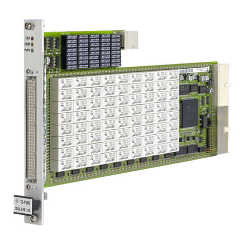
Rohde & Schwarz TS-PMB User manual

R&S®TS-PMB
Matrix Module B
User Manual
1153523312
Version 06
(;ÃÂQ<)

This manual describes the following R&S®TSVP module:
●R&S®TS-PMB
© 2022 Rohde & Schwarz GmbH & Co. KG
Muehldorfstr. 15, 81671 Muenchen, Germany
Phone: +49 89 41 29 - 0
Email: [email protected]
Internet: www.rohde-schwarz.com
Subject to change – data without tolerance limits is not binding.
R&S® is a registered trademark of Rohde & Schwarz GmbH & Co. KG.
Trade names are trademarks of the owners.
1153.5233.12 | Version 06 | R&S®TS-PMB
The following abbreviations are used throughout this manual: R&S®TS-PMB is abbreviated as R&S TS-PMB.

Contents
R&S®TS-PMB
3User Manual 1153.5233.12 ─ 06
Contents
1 Safety information (multilingual).......................................................... 5
2 Documentation overview.......................................................................9
2.1 Getting started manual................................................................................................. 9
2.2 User manuals.................................................................................................................9
2.3 System manual............................................................................................................10
2.4 Service manual............................................................................................................10
2.5 Printed safety instructions.........................................................................................10
2.6 Brochures and specifications....................................................................................10
2.7 Release notes and open source acknowledgment.................................................. 10
3 Welcome to the R&S TS-PMB............................................................. 11
4 Module tour...........................................................................................12
4.1 Status LEDs................................................................................................................. 12
4.2 Connectors X1 and X20.............................................................................................. 12
4.3 Connector X10.............................................................................................................13
4.4 Connector X30.............................................................................................................13
5 Installing the module........................................................................... 14
6 Functions..............................................................................................15
6.1 Signal concept.............................................................................................................15
6.2 Scalability.................................................................................................................... 15
6.3 Noise immunity........................................................................................................... 15
6.4 Relay matrix.................................................................................................................15
6.5 Interfaces..................................................................................................................... 16
6.6 Power supply...............................................................................................................16
7 Software................................................................................................17
7.1 Driver software............................................................................................................ 17
7.2 Softpanel......................................................................................................................17
7.3 TS-PMB program example......................................................................................... 18
8 Maintenance, storage and disposal................................................... 20
8.1 Storage.........................................................................................................................20

Contents
R&S®TS-PMB
4User Manual 1153.5233.12 ─ 06
8.2 Disposal....................................................................................................................... 20
9 Troubleshooting...................................................................................21
9.1 LED test........................................................................................................................21
9.2 Power-on test.............................................................................................................. 21
9.3 R&S TSVP self-test..................................................................................................... 22
9.4 Contacting customer support....................................................................................22
Annex.................................................................................................... 23
A Specifications.......................................................................................23
B Block diagram...................................................................................... 24
C Interface description............................................................................26
C.1 Connector X10.............................................................................................................26
C.2 Connector X20.............................................................................................................27
C.3 Connector X1...............................................................................................................28
C.4 Connector X30.............................................................................................................30

Safety information (multilingual)
R&S®TS-PMB
5User Manual 1153.5233.12 ─ 06
1 Safety information (multilingual)
This option or accessory is designed for a specific Rohde & Schwarz product. Multilin-
gual safety information is delivered with the product. Follow the provided installation
instructions.
Esta opción o este accesorio están diseñados para un producto Rohde & Schwarz
concreto. El producto va acompañado de información de seguridad en varios idiomas.
Siga las instrucciones de instalación puestas a disposición.
Diese Option oder dieses Zubehör ist für ein bestimmtes Rohde & Schwarz Produkt
vorgesehen. Mit dem Produkt werden mehrsprachige Sicherheitsinformationen gelie-
fert. Befolgen Sie die mitgelieferten Installationsanweisungen.
Cette option ou cet accessoire est conçu pour un produit Rohde & Schwarz spécifi-
que. Des informations de sécurité multilingues sont fournies avec le produit. Suivez les
instructions d'installation fournies.
Questa funzione opzionale o accessoria è progettata per un prodotto
Rohde & Schwarz specifico. Con il prodotto sono fornite informazioni sulla sicurezza in
formato multilingue. Seguire le istruzioni di installazione allegate.
Esta(e) opção ou acessório foi concebida(o) para um produto específico da
Rohde & Schwarz. Serão fornecidas informações de segurança multilingues com o
produto. Siga as instruções de instalação fornecidas.
Αυτή η προαιρετική επιλογή ή εξάρτημα έχει σχεδιαστεί για συγκεκριμένο προϊόν
Rohde & Schwarz. Μαζί με το προϊόν παρέχονται πληροφορίες ασφαλείας σε πολλές
γλώσσες. Ακολουθήστε τις παρεχόμενες οδηγίες εγκατάστασης.
Din l-għażla jew aċċessorju huma mfassla għal prodott Rohde & Schwarz speċifiku. L-
informazzjoni multilingwi dwar is-sikurezza hija pprovduta mal-prodott. Segwi l-istruzz-
jonijiet ipprovduti għall-installazzjoni.
Deze optie of dit accessoire is ontwikkeld voor een specifiek product van
Rohde & Schwarz. Het product wordt geleverd met veiligheidsinformatie in meerdere
talen. Volg de meegeleverde installatie-instructies.
Denne mulighed eller tilbehørsdel er designet til et specifikt Rohde & Schwarz pro-
dukt. En flersproget sikkerhedsanvisning leveres sammen med produktet. Følg de
medfølgende installationsanvisninger.
Detta tillval eller tillbehör är avsett för en särskild produkt från
Rohde & Schwarz. Säkerhetsinformation på flera språk medföljer produkten. Följ de
medföljande installationsanvisningarna.
Tämä vaihtoehto tai lisävaruste on suunniteltu tietylle Rohde & Schwarz -yrityksen
tuotteelle. Tuotteen mukana on toimitettu monikieliset turvallisuusohjeet. Noudata
annettuja asennusohjeita.
Dette alternativet eller ekstrautstyret er utformet for et spesifikt Rohde & Schwarz pro-
dukt. Flerspråklig sikkerhetsinformasjon leveres med produktet. Overhold installasjons-
veiledningen som følger med.

Safety information (multilingual)
R&S®TS-PMB
6User Manual 1153.5233.12 ─ 06
See valik või lisaseade on mõeldud konkreetsele Rohde & Schwarz tootele. Tootega
on kaasas mitmekeelne ohutusteave. Järgige kaasasolevaid paigaldusjuhiseid.
Šī opcija vai piederums ir izstrādāts īpaši Rohde & Schwarz produktam. Produktam
pievienota drošības informācija vairākās valodās. Ievērojiet sniegtos uzstādīšanas nor-
ādījumus.
Ši parinktis ar priedas skirti konkrečiam Rohde & Schwarz gaminiui. Su gaminiu patei-
kiama saugos informacijos keliomis kalbomis. Laikykitės pateikiamų montavimo nuro-
dymų.
Þessi auka- eða fylgibúnaður er hannaður fyrir tiltekna Rohde & Schwarz vöru. Öryggi-
supplýsingar á mörgum tungumálum fylgja með vörunni. Fylgið meðfylgjandi uppset-
ningarleiðbeiningum.
Tá an rogha nó an oiriúint seo ceaptha le haghaidh táirge Rohde & Schwarz son-
rach. Cuirtear eolas sábháilteachta ilteangach ar fáil leis an táirge. Lean na treoracha
suiteála a thugtar.
Эта опция или принадлежность предназначена для конкретного продукта
Rohde & Schwarz. В комплект поставки продукта входят инструкции по технике
безопасности на нескольких языках. Соблюдайте прилагаемые инструкции по
установке.
Ця опція або приладдя призначені для конкретного виробу
Rohde & Schwarz. Інструкції з техніки безпеки кількома мовами постачаються
разом із виробом. Дотримуйтеся наданих інструкцій зі встановлення.
Ta opcja lub akcesorium jest przeznaczone do określonego produktu
Rohde & Schwarz. Dostarczany produkt zawiera informacje w wielu językach dotyc-
zące bezpieczeństwa. Należy postępować zgodnie z dostarczonymi instrukcjami insta-
lacji.
Tato varianta nebo příslušenství je určeno pro konkrétní produkt Rohde & Schwarz.
S produktem jsou dodávány vícejazyčné bezpečnostní informace. Řiďte se přiloženými
pokyny k instalaci.
Táto verzia alebo príslušenstvo je navrhnutá pre špecifický výrobok
Rohde & Schwarz. S výrobkom sa dodávajú viacjazyčné bezpečnostné pokyny. Riaďte
sa dodanými pokynmi na inštaláciu.
Ta možnost ali dodatek je zasnovan za določen izdelek podjetja
Rohde & Schwarz. Izdelku so priložena varnostna navodila v več jezikih. Upoštevajte
priložena navodila za namestitev.
Ezt a beállítást vagy tartozékot egy adott Rohde & Schwarz termékhez tervezték. A
termékhez többnyelvű biztonsági információt mellékelünk. Kövesse a mellékelt szere-
lési utasításokat.
Тази опция или аксесоар са проектирани за специфичен продукт на
Rohde & Schwarz. Многоезикова информация за безопасност се доставя с
продукта. Следвайте предоставените инструкции за монтаж.
Ova opcija ili oprema namijenjena je za određeni proizvod tvrtke Rohde & Schwarz. Uz
proizvod su dostavljene sigurnosne napomene na više jezika. Pratite isporučene upute
za ugradnju.

Safety information (multilingual)
R&S®TS-PMB
7User Manual 1153.5233.12 ─ 06
Ova opcija ili pribor je dizajniran za određeni Rohde & Schwarz proizvod. Proizvodu su
priložene sigurnosne informacije na više jezika. Slijedite priložena uputstva za instala-
ciju.
Ova opcija ili dodatni pribor je projektovan za određeni Rohde & Schwarz proiz-
vod. Bezbednosne informacije na više jezika se isporučuju uz proizvod. Sledite dos-
tavljena uputstva za instalaciju.
Această opțiune sau acest accesoriu a fost conceput pentru un produs specific
Rohde & Schwarz. Informațiile multilingve privind siguranța sunt livrate împreună cu
produsul. Urmați instrucțiunile de instalare furnizate.
Ky opsion ose aksesor është krijuar për një produkt specifik Rohde & Schwarz. Bashkë
me produktin jepen edhe informacionet e sigurisë në shumë gjuhë. Ndiqni udhëzimet e
dhëna të instalimit.
Оваа опција или додаток се наменети за одреден производ на
Rohde & Schwarz. Со производот се испорачани повеќејазични безбедносни
упатства. Следете ги дадените упатства за инсталација.
Bu opsiyon veya aksesuar, belirli bir Rohde & Schwarz ürünü için tasarlanmıştır. Çok
dilli güvenlik uyarıları ürünle birlikte teslim edilir. Size sağlanan kurulum talimatlarına
uyun.
Şu opsiýa ýa-da esbap Rohde & Schwarz anyk önüm üçin niýetlenilen. Dürli dildäki
howpsuzlyk barada maglumat önüm bilen bile üpjün edilýär. Üpjün edilen gurnama
ugrukdyrmalaryny ýerine ýetiriň.
本选件或附件专门设计用于特定的 Rohde & Schwarz 产品。产品随附多种语言版本的安
全资讯。谨遵文件中的安装说明。
本オプションアクセサリは、特定の Rohde & Schwarz 製品向けに設計されています。
多言語で記載された安全情報が製品に付属します。付属のインストール手順に従って
ください。
이 옵션 또는 액세서리는 특정 Rohde & Schwarz 제품용으로 설계되었습니다. 제품과
함께 다국어로 작성된 안전 정보가 제공됩니다. 함께 제공된 설치 지침을 따르십시오.
本選配或配件專門設計用於特定的 Rohde & Schwarz 產品。產品隨附多種語言版本的安
全資訊。遵守文件中的安裝說明。

Safety information (multilingual)
R&S®TS-PMB
8User Manual 1153.5233.12 ─ 06
Tùy chọn hoặc phụ kiện này dành riêng cho một sản phẩm Rohde & Schwarz cụ thể.
Thông tin an toàn đa ngôn ngữ được cung cấp kèm theo sản phẩm. Thực hiện theo
hướng dẫn lắp đặt kèm theo.
ตัวเลือกหรืออุปกรณเสริมนีออกแบบมาสำหรับผลิตภัณฑ Rohde & Schwarz โดยเฉพาะ โดยจะมีการจัดสงขอมูลดานความปลอดภัย-
หลายภาษามาใหพรอมกับผลิตภัณฑ ปฏิบัติตามคำแนะนำในการติดตังทีใหไว
Pilihan atau aksesori ini direka bentuk untuk produk Rohde & Schwarz yang ter-
tentu. Maklumat keselamatan berbilang bahasa disertakan bersama produk. Ikut ara-
han pemasangan yang diberikan.
Opsi atau aksesori ini dirancang untuk produk Rohde & Schwarz tertentu. Informasi
keamanan dalam beberapa bahasa juga disertakan bersama produk. Ikuti petunjuk
pemasangan yang disediakan.
Esta opción o este accesorio están diseñados para un producto Rohde & Schwarz en
concreto. El producto va acompañado de información de seguridad en varios idiomas.
Siga las instrucciones de instalación proporcionadas con el producto.
Esta opção ou acessório foi desenvolvido para um produto Rohde & Schwarz especí-
fico. Informações de segurança em vários idiomas acompanham o produto. Siga as
instruções de instalação disponibilizadas.

Documentation overview
R&S®TS-PMB
9User Manual 1153.5233.12 ─ 06
2 Documentation overview
This section provides an overview of the R&S TSVP (test system versatile platform)
user documentation.
All documents are delivered with the Generic Test Software Library ("R&S GTSL")
installation package. After installing the software, you can open all the documentation
from the Windows "Start" menu. Additionally, you can find detailed information about
the software interfaces in the "R&S GTSL Help" folder in the Windows "Start" menu.
The user documentation and "R&S GTSL" installation package are also available for
download in GLORIS at:
https://gloris.rohde-schwarz.com/
For details, see the R&S TSVP Getting Started manual.
2.1 Getting started manual
Introduces the R&S TSVP (test system versatile platform) and describes how to set up
and start working with the product. It includes safety information.
A printed version is delivered with the instrument.
2.2 User manuals
Separate manuals are provided for the base units, the individual plug-in module types,
as well as for the control software and the calibration tool:
●Base unit manual
The base unit user manuals introduce the base units and describes how to set up
and operate the product. It includes safety information and information on mainte-
nance and instrument interfaces. It includes the contents of the getting started
manual.
●Plug-in module manuals
Contain the description of the specific modules. Basic information on setting up the
R&S TSVP (test system versatile platform) is not included.
●In-System calibration user manuals
Provide all the information required for installation and operation of the in-system
calibration R&S TS-ISC solution.
●Control software
– R&S GTSL
Generic Test Software Library
– R&S EGTSL
Enhanced Generic Test Software Library
– R&S IC-Check
User manuals

Documentation overview
R&S®TS-PMB
10User Manual 1153.5233.12 ─ 06
Generic Test Software Library
2.3 System manual
Describes the complete R&S TSVP (test system versatile platform) as a whole, includ-
ing the combined use of R&S CompactTSVP and R&S PowerTSVP, plug-in modules
and generic test software. It also includes typical use cases.
Additionally, it describes known installation problems (hardware and software) along
with possible solutions.
2.4 Service manual
Describes the self-test to check correct operation, troubleshooting and fault elimination,
and contains mechanical drawings and spare part lists.
2.5 Printed safety instructions
Provides safety information in many languages. The printed document is delivered with
the product.
2.6 Brochures and specifications
Separate brochures are provided for the base unit, the individual plug-in module types,
as well as for the control software. The brochures provide an overview of the base
units and each additional module, and also contain the technical specifications. They
also list the hardware options and their order numbers, and optional accessories.
2.7 Release notes and open source acknowledgment
The release notes list new features, improvements and known issues of the current
software version. In addition, the available firmware versions and the firmware update
procedure for plug-in modules are described.
The open-source acknowledgment document provides verbatim license texts of the
used open source software.
Release notes and open source acknowledgment

Welcome to the R&S TS-PMB
R&S®TS-PMB
11User Manual 1153.5233.12 ─ 06
3 Welcome to the R&S TS-PMB
The Rohde & Schwarz matrix module B R&S TS-PMB allows the universal intercon-
nection of test points and measuring instruments. This can be done locally or using the
analog bus. The R&S TS-PMB is intended for the use in the R&S TSVP base units.
Typical product test applications are in the fields of communications, automotive elec-
tronics and general industrial electronics, especially for analog in-circuit testing with a
large number of channels.
Features of the R&S TS-PMB
●Access to the analog bus (8-wire)
●Full matrix with 4 buses with 90 pins
●Full matrix with 8 buses with 45 pins
●3 Instrument ports
●Parallel test with two 4-wire systems
●In-circuit test wiring for 6-wire measurements
●Control bus: CAN
●Self-test of all relays via analog bus and plug-in module R&S TS-PSAM

Module tour
R&S®TS-PMB
12User Manual 1153.5233.12 ─ 06
4 Module tour
The R&S TS-PMB is designed as a long plug-in board for front mounting in the
R&S TSVP base unit.
Figure 4-1: Overview of connectors and other elements
LEDs = Chapter 4.1, "Status LEDs", on page 12
4.1 Status LEDs
The LEDs on the front indicate the current status of the module.
●"PWR" (green LED)
Indicates that all necessary supply voltages are present.
●"COM" (yellow LED)
Indicates data exchange via the interface.
●"ERR" (red LED)
Indicates an error condition if illuminated.
4.2 Connectors X1 and X20
Type: Control bus
Interface to connect the module to the control backplane of the base units.
Modules with version 3.x or higher are equipped with the X1 connnector, starting at
serial no. 100183 (first delivery in 2004).
Connectors X1 and X20

Module tour
R&S®TS-PMB
13User Manual 1153.5233.12 ─ 06
See Chapter C.3, "Connector X1", on page 28 and Chapter C.2, "Connector X20",
on page 27 for a detailed description of the connectors.
4.3 Connector X10
Interface to connect test objects and UUTs to the module.
See Chapter C.1, "Connector X10", on page 26 for a detailed description of the con-
nector.
4.4 Connector X30
Type: Analog bus
Interface to connect the module to the analog bus backplane in the housing of the
R&S TSVP.
See Chapter C.4, "Connector X30", on page 30 for a detailed description of the con-
nector.
Connector X30

Installing the module
R&S®TS-PMB
14User Manual 1153.5233.12 ─ 06
5 Installing the module
The R&S TS-PMB is a module installed on the front panel of the base unit.
1. Install the module as described in the user manuals of the base units.
2. WARNING! Risk of electric shock. The test environment, e.g the UUT or additional
power supplies, can supply high voltages to the instruments. In this case, the volt-
age can also apply to the signal output connectors of the R&S TSVP, in particular
the analog bus connector X2.
Therefore, do not connect or disconnect devices from the X2 connectors while con-
nected to an external power supply or UUT.
Always connect both ends of the cable connecting the R&S CompactTSVP and
R&S PowerTSVP. Thus, you avoid the risk of touching the X2 connector with a
possibly hazardous voltage applied.
Take the system into operation as described in the user manuals of the base units.
(starting with R&S CompactTSVP with backplane version V4.x)
Matrix modules B R&S TS-PMB with change status V2.x (recognizable from the lack of
connector X1, last delivery in 2004) require a hardware change to TAZ 2.14 and a rear
IO module R&S TS-PRIO plugged in to operated in the R&S CompactTSVP with back-
plane version V4.x (starting with serial number 100109 on 09/2005). The 5-V power
supply and CAN bus are supplied via the R&S TS-PRIO.

Functions
R&S®TS-PMB
15User Manual 1153.5233.12 ─ 06
6 Functions
6.1 Signal concept
The R&S TS-PMB allows the optional connection of measuring instruments to pins on
test products. Connections can be made locally within the module or with other mod-
ules using the R&S analog bus.
The ability to connect measuring instruments to the back of the R&S TSVP avoids
cross-connections at the adapter interface. The unit's extreme compactness makes it
possible to accommodate measuring systems with a number of PXI instruments and a
switch panel with a large number of pins in a single device (one-box solution), making
is particularly suitable for in-circuit testing.
The ground can be connected to the front connector via the ground relay (GND -
GNDNO).
SeeChapter B, "Block diagram", on page 24 for details.
6.2 Scalability
The R&S TS-PMB has two switching matrices (4 x 45). These can also be configured
as 8 buses x 45 pins with external connection or 4 buses x 90 pins, e.g. using plug-in
module R&S TS-PSAM via the analog bus (see Figure B-2).
Three additional instrument inputs (IL1 ... IL3) can be used to connect measuring
instruments at the rear.
The switch panel can be divided into two 4-wire part buses for the parallel test. The
number of pins can be increased with up to 16 modules adding the R&S PowerTSVP.
6.3 Noise immunity
The signal concept with the analog bus remote from the Compact PCI bus and the trig-
gering via the CAN bus guarantee good signal quality. Despite the unit's compact size,
DC and AC voltages up 120 V (rms) can be connected and passed to other modules.
6.4 Relay matrix
The matrix is designed as a part matrix, i.e. each even I/O channel (e.g. P2) can be
switched to an even part bus (e.g. LABA2) and each odd I/O channel (e.g. P1) can be
switched to an off part bus (e.g. LABA1) (see Chapter B, "Block diagram",
Relay matrix

Functions
R&S®TS-PMB
16User Manual 1153.5233.12 ─ 06
on page 24). This does not apply to channels IL1 ... IL3, which can be switched to all
lines of the local analog bus.
Coupling relays separate the local analog bus lines (LAB) on the R&S TS-PMB from
the bus lines on the analog bus backplane. The firmware automatically switches these
relays selectively when at least one I/O channel is switched to the corresponding local
analog bus. When an I/O channel is no longer switched to a bus, the corresponding
coupling relay is automatically opened. This function can be turned on or off at any
time. The coupling relays can also be switched manually.
6.5 Interfaces
(see Figure B-2)
The SPI interface (Serial Peripheral Interface) is used for communication with rear I/O
modules. The R&S TS-PMB is controlled via CAN interface (Controller Area Network).
6.6 Power supply
The R&S TS-PMB is operated with a voltage of 5 V. The power supply is provided
through connector X20 for Versions V1.x and V2.x. In version V3.x or higher (first deliv-
ery in 2004), the power supply is provided via connector X20 or connector X1. All ver-
sions of the R&S TS-PMB can be operated in the R&S TSVP base units.
Since the R&S CompactTSVP no longer makes a 5 V power supply available on con-
nector X20 starting with backplane version V4.x in 09/2005, only R&S TS-PMB mod-
ules of version V3.x or higher can be operated with this backplane version. R&S TS-
PMB modules of version V2.x require a change to TAZ 2.14 and a rear IO module
R&S TS-PRIO, which enables the CAN bus lines und supplies the front module with 5
V.
Power supply

Software
R&S®TS-PMB
17User Manual 1153.5233.12 ─ 06
7 Software
7.1 Driver software
A LabWindows CVI driver is provided for the R&S TS-PMB . This driver satisfies the
IVI Switch specification. The driver is part of the ROHDE & SCHWARZ GTSL software.
All the functions of the driver are described fully in the on-line help.
During driver installation, the following software modules are installed:
Table 7-1: Driver installation R&S TS-PMB
Module Path Comment
rspmb.dll <GTSL directory>\Bin Driver
rspmb.chm <GTSL directory>\Bin Help files
rspmb.fp <GTSL directory>\Bin LabWindows CVI Function Panel file, function panels for
CVI development interface
rspmb.sub <GTSL directory>\Bin LabWindows CVI attribute file. This file is required by
some „function panels“.
rspmb.lib <GTSL directory>\Bin Import Library
rspmb.h <GTSL directory>\
Include
Header file for the driver
To use the driver, the IVI and VISA libraries from National Instruments are necessary.
7.2 Softpanel
The software package of the R&S TS-PMB includes a softpanel (see example in Fig-
ure 7-1). The softpanel enables the user to execute the functions of the R&S TS-PMB
listed in the menu with on-screen mouse clicks.
Softpanel

Software
R&S®TS-PMB
18User Manual 1153.5233.12 ─ 06
Figure 7-1: Softpanel R&S TS-PMB (example)
7.3 TS-PMB program example
/*
Connection between ABa1 and ABb1 with TS-PMB in Slot 12
The coding rules of a GTSL software like
allocating and locking the resource, or error handling
are not considered in this example.
It´s just to show the function calls to get the connection.
*/
/*
rspmb ivi-driver header file
*/
#include "rspmb.h"
static ViStatus s_status;
TS-PMB program example

Software
R&S®TS-PMB
19User Manual 1153.5233.12 ─ 06
main()
{
/*
Creates a new IVI instrument driver and optionally sets the initial
state of the session attributes
"CAN0::0::1::12": CAN board 0, Bus Controller 0, Frame 1, Slot 12
*/
s_status = rspmb_InitWithOptions ("CAN0::0::1::12", VI_TRUE, VI_TRUE, "", & handle);
/*
This function sets/opens automatically the bus coupling relays
(local analog bus to analog bus) if a path is created/closed.
*/
s_status = rspmb_SetAttributeViBoolean (handle, "", RSPMB_ATTR_CR_AUTO, VI_TRUE);
/*
This function creates a path between channel ABa1 and P1.
The driver calculates the shortest path between the two channels.
*/
s_status = rspmb_Connect (handle, "ABa1", "P1");
s_status = rspmb_Connect (handle, "ABb1", "P1");
/*
Connection between ABa1 and ABb1 exists.
*/
/*
Opens the path between Channel ABa1 and LABa1.
*/
s_status = rspmb_Disconnect (handle, "ABa1", "P1");
s_status = rspmb_Disconnect (handle, "ABb1", "P1");
s_status = rspmb_close (handle);
}
TS-PMB program example

Maintenance, storage and disposal
R&S®TS-PMB
20User Manual 1153.5233.12 ─ 06
8 Maintenance, storage and disposal
8.1 Storage
Protect the product against dust. Ensure that the environmental conditions, e.g. tem-
perature range and climatic load, meet the values specified in the data sheet.
8.2 Disposal
Rohde & Schwarz is committed to making careful, ecologically sound use of natural
resources and minimizing the environmental footprint of our products. Help us by dis-
posing of waste in a way that causes minimum environmental impact.
Disposing electrical and electronic equipment
A product that is labeled as follows cannot be disposed of in normal household waste
after it has come to the end of its service life. Even disposal via the municipal collection
points for waste electrical and electronic equipment is not permitted.
Figure 8-1: Labeling in line with EU directive WEEE
Rohde & Schwarz has developed a disposal concept for the eco-friendly disposal or
recycling of waste material. As a manufacturer, Rohde & Schwarz completely fulfills its
obligation to take back and dispose of electrical and electronic waste. Contact your
local service representative to dispose of the product.
Disposal
Table of contents
Other Rohde & Schwarz Control Unit manuals