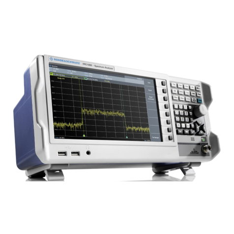
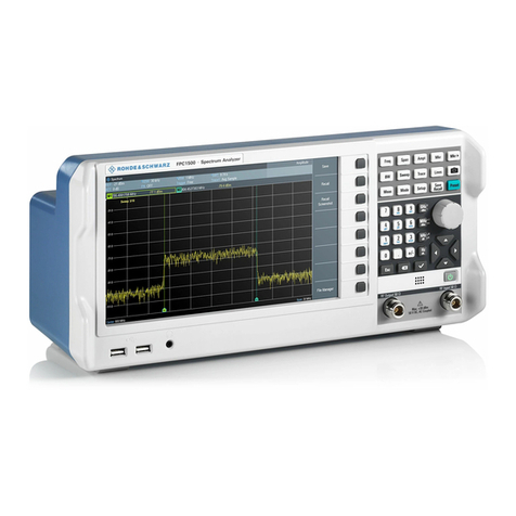
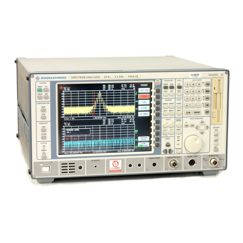
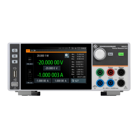
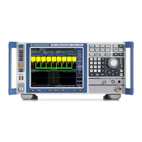
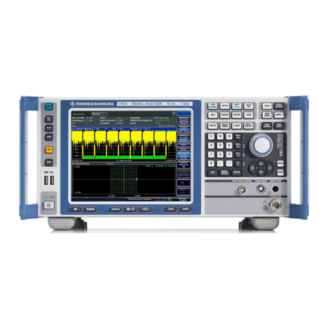
150MHz Mixed Signal CombiScope®HM1508-2
All data valid at 23 °C after 30 minute warm-up
Vertical Deflection
Channels:
Analog: 2
Digital: 2 + 2 Logic Channels
Operating Modes:
Analog: CH 1 or CH 2 separate, DUAL (CH 1 and
CH 2 alternate or chopped), Addition
Digital: Analog Signal Channels CH 1 or CH 2
separate, DUAL (CH 1 and CH 2), Addition
Logic Signal Channels: CH 3 and CH 4
X in XY-Mode: CH 1
Invert: CH 1, CH 2
Bandwidth (-3 dB): 2x0…150 MHz
Rise time: ‹ 2.3 ns
Bandwith limiting (selectable):approx. 20 MHz (5 mV/div.…20 V/div.)
Deflection Coefficients(CH 1,2):14 calibrated steps
1…2 mV/div. (10 MHz) ± 5 % (0…10 MHz (-3 dB))
5 mV…20 V/div. ± 3 % (1-2-5 sequence)
variable (uncalibrated): › 2.5 :1 to › 50 V/div.
Inputs CH 1, 2:
Input Impedance: 1 MΩ II 15 pF
Coupling: DC, AC, GND (ground)
Max. Input Voltage: 400V (DC + peak AC)
Y Delay Line (analog): 70 ns
Measuring Circuits: Measuring Category I
Digital mode only:
Logic Channels: CH 3, CH 4
Select. switching thresholds: TTL, CMOS, ECL
User definable thresholds: 3
within the range: -2…+3V
Analog mode only:
Auxiliary input: CH 4: 100 V (DC + peak AC)
Function (selectable): Extern Trigger, Z (unblank)
Coupling: AC, DC
Max. input voltage: 100 V (DC + peak AC)
Triggering
Analog and Digital Mode
Automatic (Peak to Peak):
Min. signal height: 5mm
Frequency range: 10 Hz…250 MHz
Level control range: from Peak- to Peak+
Normal (without peak):
Min. signal height: 5mm
Frequency range: 0…250 MHz
Level control range: -10…+10 div.
Operating modes: Slope/Video/Logic
Slope: Rising, falling, both
Sources: CH 1, CH 2, alt. CH 1/2 (≥8 mm, analog
mode only), Line, Ext.
Coupling: AC: 10 Hz…250 MHz
DC: 0…250 MHz
HF: 30 kHz…250 MHz
LF: 0…5 kHz
Noise Rej. switchable
Video: pos./neg. Sync. Impulse
Standards: 525 Line/60 Hz Systems
625 Line/50 Hz Systems
Field: even/odd/both
Line: all/line number selectable
Source: CH 1, CH 2, Ext.
Indicator for trigger action: LED
External Trigger via: CH 4 (0.3 Vpp, 150 MHz)
Coupling: AC, DC
Max. input voltage: 100 V (DC +peak AC)
Digital mode:
Logic: AND/OR, TRUE/FALSE
Source: CH1 or 2, CH3 and CH4
State: X, H, L
Pre/ Post Trigger: -100…+400% related to complete memory
Analog mode
2nd Trigger
Min. signal height: 5mm
Frequency range: 0…250 MHz
Coupling: DC
Level control range: -10…+10 div.
Horizontal Deflection
Analog mode
Operating modes: A, ALT (alternating A/B), B
Time base A: 50 ns/div.…0.5 s/div. (1-2-5 sequence)
Time base B: 50 ns/div.…20 ms/div. (1-2-5 sequence)
Accuracy A and B: ±3%
X Magnification x10: to 5 ns/div.
Accuracy: ±5%
Variable time base A/B: cont. 1:2.5
Hold Off time: var. 1:10 LED-Indication
Bandwidth X-Amplifier: 0…3 MHz (-3 dB)
X Y phase shift ‹ 3°: ‹ 220 kHz
Digital mode
Time base range (1-2-5 sequence)
Refresh Mode: 5 ns/div.…20 ms/div.
with Peak Detect: 2…20 ms/div. (min. Pulse Width 10 ns)
Roll Mode: 50 ms/div.…50 s/div.
Accuracy time base
Time base: 50 ppm
Display: ±1%
MEMORY ZOOM: max. 50,000:1
Bandwidth X-Amplifier: 0…150 MHz (-3 dB)
XY phase shift ‹ 3°: ‹ 100 MHz
Digital Storage
Sampling Rate (real time): Analog channels: max. 2 x 500MSa/s or
1 x 1 GSa/s (interleaved); Logic Channels:
2 x 500 MSa/s
Sampling Rate (random sampling): 10GSa/s
Bandwidth: 2 x 0…150 MHz (random)
Memory: 2 x 1 MPts (analog); 2 x 1 MPts (logic)
Operating modes: Refresh, Average, Envelope/
Roll: Free Run/Triggered, Peak-Detect
Resolution (vertical): 8 Bit (25 Pts/div.)
Resolution (horizontal):
Yt: 11Bit (200 Pts/div.)
XY: 8Bit (25 Pts /div.)
Interpolation: Sinx/x, Dot Join (linear),
Delay: 1 Million x 1/Sampling Rate to
4 Million x 1/Sampling Rate
Display refresh rate: max.170/s at 1 MPts
Display: Dots (acquired points only), Vectors (partly
interpolated), optimal (complete memory
weighting and vectors)
Reference Memories: 9 with 2 kPts each (for recorded signals)
Display: 2 signals of 9 (free selectable)
FFT Mode
Display X: Frequency Range
Disaplay Y: True rms value of spectrum
Scaling: Linear or logarithmic
Level display: dBV, V
Window: Square, Hanning, Hamming, Blackman
Control: Center frequency, Span
Marker: Frequency, Amplitude
Zoom (frequency axis): up to x 20
Operation/Measuring/Interfaces
Operation: Menu (multilingual), Autoset,
help functions (multilingual)
Save/Recall (instrument parameter settings): 9
Signal display: max. 4 signals or 4 traces
analog: CH 1, 2 (Time Base A) in combination with
CH 1, 2 (Time Base B)
digital: CH 1, 2 and CH 3, 4 or ZOOM or Reference
or Mathematics
USB Memory-Stick:
Save/Recall external:
Instrument settings and Signals: CH 1, 2 and CH 3, 4 or ZOOM or
Reference or Mathematics
Screen-shot: as Bitmap
Signal display data (2k per channel): Binary (SCPI-Data), Text (ASCII-
Format), CSV (Spread Sheet)
Frequency counter:
6 digit resolution: › 1 MHz…250 MHz
5 digit resolution: 0.5 Hz…1 MHz
Accuracy: 50 ppm
Auto Measurements:
Analog mode: Frequency, Period, Vdc, Vpp, Vp+, Vp-
also in digital mode: Vrms, Vavg
Cursor Measurements:
Analog mode: Δt, 1/Δt (f), tr, ΔV, V to GND, ratio X, ratio Y
plus in digital mode: Vpp, Vp+, Vp-, Vavg, Vrms, pulse count
