Roland Dm-10 User manual

202
Copyright © 2004 ROLAND CORPORATION
All rights reserved. No part of this publication may be reproduced in any form without
the written permission of ROLAND CORPORATION.
201b
Before using this unit, carefully read the sections entitled: “IMPORTANT
SAFETY INSTRUCTIONS” (p. 2), “USING THE UNIT SAFELY” (pp. 3–4), and
“IMPORTANT NOTES” (p. 5). These sections provide important information
concerning the proper operation of the unit. Additionally, in order to feel
assured that you have gained a good grasp of every feature provided by your
new unit, Owner’s manual should be read in its entirety. The manual should be
saved and kept on hand as a convenient reference.
Owner’s Manual
Bedienungsanleitung
Mode d’emploi
Manuale d’uso
Manual del usuario
DM-10_efgis 1 ページ 2004年1月8日 木曜日 午後1時59分

2
CAUTION
RISK OF ELECTRIC SHOCK
DO NOT OPEN
ATTENTION: RISQUE DE CHOC ELECTRIQUE NE PAS OUVRIR
CAUTION: TO REDUCE THE RISK OF ELECTRIC SHOCK,
DO NOT REMOVE COVER (OR BACK).
NO USER-SERVICEABLE PARTS INSIDE.
REFER SERVICING TO QUALIFIED SERVICE PERSONNEL.
The lightning flash with arrowhead symbol, within an
equilateral triangle, is intended to alert the user to the
presence of uninsulated “dangerous voltage” within the
product’s enclosure that may be of sufficient magnitude to
constitute a risk of electric shock to persons.
The exclamation point within an equilateral triangle is
intended to alert the user to the presence of important
operating and maintenance (servicing) instructions in the
literature accompanying the product.
INSTRUCTIONS PERTAINING TO A RISK OF FIRE, ELECTRIC SHOCK, OR INJURY TO PERSONS.
IMPORTANT SAFETY INSTRUCTIONS
SAVE THESE INSTRUCTIONS
WARNING - When using electric products, basic precautions should always be followed, including the following:
1. Read these instructions.
2. Keep these instructions.
3. Heed all warnings.
4. Follow all instructions.
5. Do not use this apparatus near water.
6. Clean only with a dry cloth.
7. Do not block any of the ventilation openings. Install in
accordance with the manufacturers instructions.
8. Do not install near any heat sources such as radiators,
heat registers, stoves, or other apparatus (including
amplifiers) that produce heat.
9. Do not defeat the safety purpose of the polarized or
grounding-type plug. A polarized plug has two blades with
one wider than the other. A grounding type plug has two
blades and a third grounding prong. The wide blade or the
third prong are provided for your safety. When the provided
plug does not fit into your outlet, consult an electrician for
replacement of the obsolete outlet.
10. Protect the power cord from being walked on or pinched
particularly at plugs, convenience receptacles, and the
point where they exit from the apparatus.
11. Only use attachments/accessories specified by the
manufacturer.
12. Never use with a cart, stand, tripod, bracket,
or table except as specified by the
manufacturer, or sold with the apparatus.
When a cart is used, use caution when
moving the cart/apparatus combination to
avoid injury from tip-over.
13. Unplug this apparatus during lightning storms or when
unused for long periods of time.
14. Refer all servicing to qualified service personnel. Servicing
is required when the apparatus has been damaged in any
way, such as power-supply cord or plug is damaged, liquid
has been spilled or objects have fallen into the apparatus,
the apparatus has been exposed to rain or moisture, does
not operate normally, or has been dropped.
IMPORTANT: THE WIRES IN THIS MAINS LEAD ARE COLOURED IN ACCORDANCE WITH THE FOLLOWING CODE.
BLUE:
BROWN:
As the colours of the wires in the mains lead of this apparatus may not correspond with the coloured markings identifying
the terminals in your plug, proceed as follows:
The wire which is coloured BLUE must be connected to the terminal which is marked with the letter N or coloured BLACK.
The wire which is coloured BROWN must be connected to the terminal which is marked with the letter L or coloured RED.
Under no circumstances must either of the above wires be connected to the earth terminal of a three pin plug.
NEUTRAL
LIVE
For the U.K.
DM-10_efgis 2 ページ 2004年1月8日 木曜日 午後1時59分

3
USING THE UNIT SAFELY
001
•Before using this unit, make sure to read the instructions
below, and the Owner’s Manual.
..........................................................................................................
002a
• Do not open or perform any internal modifications on
the unit.
..........................................................................................................
003
•Do not attempt to repair the unit, or replace parts within
it (except when this manual provides specific instruc-
tions directing you to do so). Refer all servicing to your
retailer, the nearest Roland Service Center, or an autho-
rized Roland distributor, as listed on the “Information”
page.
..........................................................................................................
004
• Never use or store the unit in places that are:
• Subject to temperature extremes (e.g., direct sunlight
in an enclosed vehicle, near a heating duct, on top of
heat-generating equipment); or are
• Damp (e.g., baths, washrooms, on wet floors); or are
• Humid; or are
• Exposed to rain; or are
• Dusty; or are
• Subject to high levels of vibration.
..........................................................................................................
007
• Make sure you always have the unit placed so it is level
and sure to remain stable. Never place it on stands that
could wobble, or on inclined surfaces.
..........................................................................................................
008a
• The unit should be connected to a power supply only of
the type described in the operating instructions, or as
marked on the rear side of unit.
..........................................................................................................
008e
• Use only the attached power-supply cord. Also, the
supplied power cord must not be used with any other
device.
..........................................................................................................
009
• Do not excessively twist or bend the power cord, nor
place heavy objects on it. Doing so can damage the cord,
producing severed elements and short circuits.
Damaged cords are fire and shock hazards!
..........................................................................................................
010
• This unit, either alone or in combination with an
amplifier and headphones or speakers, may be capable
of producing sound levels that could cause permanent
hearing loss. Do not operate for a long period of time at a
high volume level, or at a level that is uncomfortable. If
you experience any hearing loss or ringing in the ears,
you should immediately stop using the unit, and consult
an audiologist.
..........................................................................................................
011
•Do not allow any objects (e.g., flammable material, coins,
pins); or liquids of any kind (water, soft drinks, etc.) to
penetrate the unit.
..........................................................................................................
012a:
• Immediately turn the power off, remove the power cord
from the outlet, and request servicing by your retailer,
the nearest Roland Service Center, or an authorized
Roland distributor, as listed on the “Information” page
when:
• The power-supply cord, or the plug has been damaged; or
• If smoke or unusual odor occurs
• Objects have fallen into, or liquid has been spilled onto the
unit; or
• The unit has been exposed to rain (or otherwise has become
wet); or
• The unit does not appear to operate normally or exhibits a
marked change in performance.
..........................................................................................................
Used for instructions intended to alert
the user to the risk of injury or material
damage should the unit be used
improperly.
* Material damage refers to damage or
other adverse effects caused with
respect to the home and all its
furnishings, as well to domestic
animals or pets.
Used for instructions intended to alert
the user to the risk of death or severe
injury should the unit be used
improperly.
The ●symbol alerts the user to things that must be
carried out. The specific thing that must be done is
indicated by the design contained within the circle. In
the case of the symbol at left, it means that the power-
cord plug must be unplugged from the outlet.
The symbol alerts the user to important instructions
or warnings.The specific meaning of the symbol is
determined by the design contained within the
triangle. In the case of the symbol at left, it is used for
general cautions, warnings, or alerts to danger.
The symbol alerts the user to items that must never
be carried out (are forbidden). The specific thing that
must not be done is indicated by the design contained
within the circle. In the case of the symbol at left, it
means that the unit must never be disassembled.
DM-10_efgis 3 ページ 2004年1月8日 木曜日 午後1時59分

4
013
• In households with small children, an adult should
provide supervision until the child is capable of
following all the rules essential for the safe operation of
the unit.
..........................................................................................................
014
• Protect the unit from strong impact.
(Do not drop it!)
..........................................................................................................
015
• Do not force the unit’s power-supply cord to share an
outlet with an unreasonable number of other devices. Be
especially careful when using extension cords—the total
power used by all devices you have connected to the
extension cord’s outlet must never exceed the power
rating (watts/amperes) for the extension cord. Excessive
loads can cause the insulation on the cord to heat up
and eventually melt through.
..........................................................................................................
016
• Before using the unit in a foreign country, consult with
your retailer, the nearest Roland Service Center, or an
authorized Roland distributor, as listed on the “Infor-
mation” page.
..........................................................................................................
026
• Do not put anything that contains water (e.g., flower
vases) on this unit. Also, avoid the use of insecticides,
perfumes, alcohol, nail polish, spray cans, etc., near the
unit. Swiftly wipe away any liquid that spills on the unit
using a dry, soft cloth.
..........................................................................................................
101a
•The unit should be located so that its location or position
does not interfere with its proper ventilation.
..........................................................................................................
102b
• Always grasp only the plug on the power-supply cord
when plugging into, or unplugging from, an outlet or
this unit.
..........................................................................................................
103a:
• At regular intervals, you should unplug the power plug
and clean it by using a dry cloth to wipe all dust and
other accumulations away from its prongs. Also,
disconnect the power plug from the power outlet
whenever the unit is to remain unused for an extended
period of time. Any accumulation of dust between the
power plug and the power outlet can result in poor
insulation and lead to fire.
..........................................................................................................
104
• Try to prevent cords and cables from becoming
entangled. Also, all cords and cables should be placed so
they are out of the reach of children.
..........................................................................................................
106
• Never climb on top of, nor place heavy objects on the
unit.
..........................................................................................................
107b
• Never handle the power cord or its plugs with wet
hands when plugging into, or unplugging from, an
outlet or this unit.
..........................................................................................................
108a
• Before moving the unit, disconnect the power plug from
the outlet, and pull out all cords from external devices.
..........................................................................................................
109a
• Before cleaning the unit, turn off the power and unplug
the power cord from the outlet.
..........................................................................................................
110a
• Whenever you suspect the possibility of lightning in
your area, pull the plug on the power cord out of the
outlet.
..........................................................................................................
DM-10_efgis 4 ページ 2004年1月8日 木曜日 午後1時59分

5
IMPORTANT NOTES
291b
In addition to the items listed under “IMPORTANT SAFETY INSTRUCTIONS” and “USING THE UNIT SAFELY” on pages
2–4, please read and observe the following:
Power Supply
301
• Do not connect this unit to same electrical outlet that is being
used by an electrical appliance that is controlled by an inverter
(such as a refrigerator, washing machine, microwave oven, or air
conditioner), or that contains a motor. Depending on the way in
which the electrical appliance is used, power supply noise may
cause this unit to malfunction or may produce audible noise. If it
is not practical to use a separate electrical outlet, connect a power
supply noise filter between this unit and the electrical outlet.
307
• Before connecting this unit to other devices, turn off the power
to all units. This will help prevent malfunctions and/or damage
to speakers or other devices.
308
•Although the LCD and LEDs are switched off when the POWER
switch is switched off, this does not mean that the unit has been
completely disconnected from the source of power. If you need
to turn off the power completely, first turn off the POWER
switch, then unplug the power cord from the power outlet. For
this reason, the outlet into which you choose to connect the
power cord’s plug should be one that is within easy reach.
Placement
351
• Using the unit near power amplifiers (or other equipment
containing large power transformers) may induce hum. To
alleviate the problem, change the orientation of this unit; or
move it farther away from the source of interference.
352a
•This device may interfere with radio and television reception. Do
not use this device in the vicinity of such receivers.
352b
• Noise may be produced if wireless communications devices,
such as cell phones, are operated in the vicinity of this unit. Such
noise could occur when receiving or initiating a call, or while
conversing. Should you experience such problems, you should
relocate such wireless devices so they are at a greater distance
from this unit, or switch them off.
354b
• Do not expose the unit to direct sunlight, place it near devices
that radiate heat, leave it inside an enclosed vehicle, or otherwise
subject it to temperature extremes. Also, do not allow lighting
devices that normally are used while their light source is very
close to the unit (such as a piano light), or powerful spotlights to
shine upon the same area of the unit for extended periods of
time. Excessive heat can deform or discolor the unit.
355b
• When moved from one location to another where the temper-
ature and/or humidity is very different, water droplets (conden-
sation) may form inside the unit. Damage or malfunction may
result if you attempt to use the unit in this condition. Therefore,
before using the unit, you must allow it to stand for several
hours, until the condensation has completely evaporated.
356
• Do not allow rubber, vinyl, or similar materials to remain on the
unit for long periods of time. Such objects can discolor or
otherwise harmfully affect the finish.
359
• Do not paste stickers, decals, or the like to this instrument.
Peeling such matter off the instrument may damage the exterior
finish.
Add
• Do not allow objects to remain on top of the unit while it is in
operation. Placing heavy objects on this unit may result in injury
if it overturns or falls.
Maintenance
401b
• To clean the unit, use a dry, soft cloth; or one that is slightly
dampened. Try to wipe the entire surface using an equal amount
of strength, moving the cloth along with the grain of the wood.
Rubbing too hard in the same area can damage the finish.
402
• Never use benzine, thinners, alcohol or solvents of any kind, to
avoid the possibility of discoloration and/or deformation.
Additional Precautions
553
• Use a reasonable amount of care when using the unit’s buttons,
sliders, or other controls; and when using its jacks and
connectors. Rough handling can lead to malfunctions.
556
•When connecting / disconnecting all cables, grasp the connector
itself—never pull on the cable. This way you will avoid causing
shorts, or damage to the cable’s internal elements.
557
•Asmall amount of heat will radiate from the unit during normal
operation.
558a
• To avoid disturbing your neighbors, try to keep the unit’s
volume at reasonable levels. You may prefer to use headphones,
so you do not need to be concerned about those around you
(especially when it is late at night).
559a
• When you need to transport the unit, package it in the box
(including padding) that it came in, if possible. Otherwise, you
will need to use equivalent packaging materials.
562
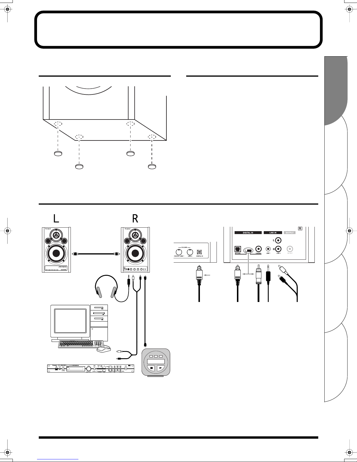
• Use a cable from Roland to make the connection. If using some
other make of connection cable, please note the following
precautions.
• Some connection cables contain resistors. Do not use cables
that incorporate resistors for connecting to this unit. The use
of such cables can cause the sound level to be extremely low,
or impossible to hear. For information on cable specifications,
contact the manufacturer of the cable.
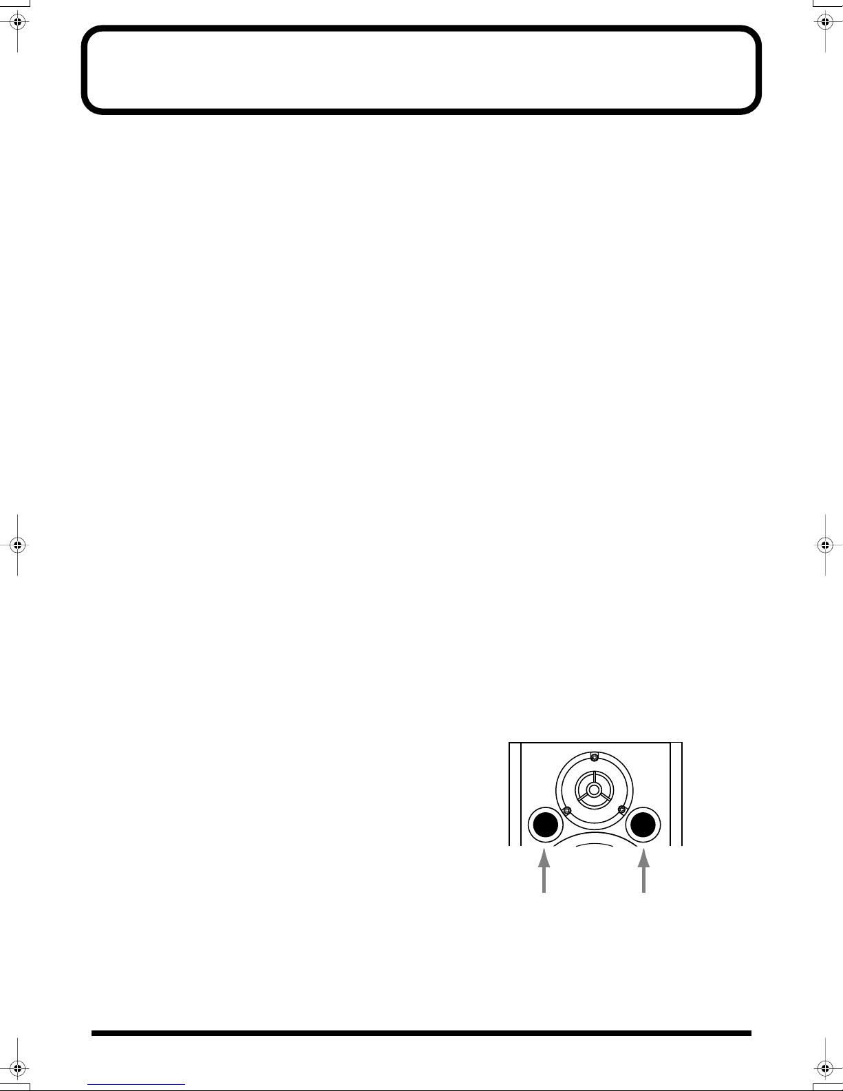
Add
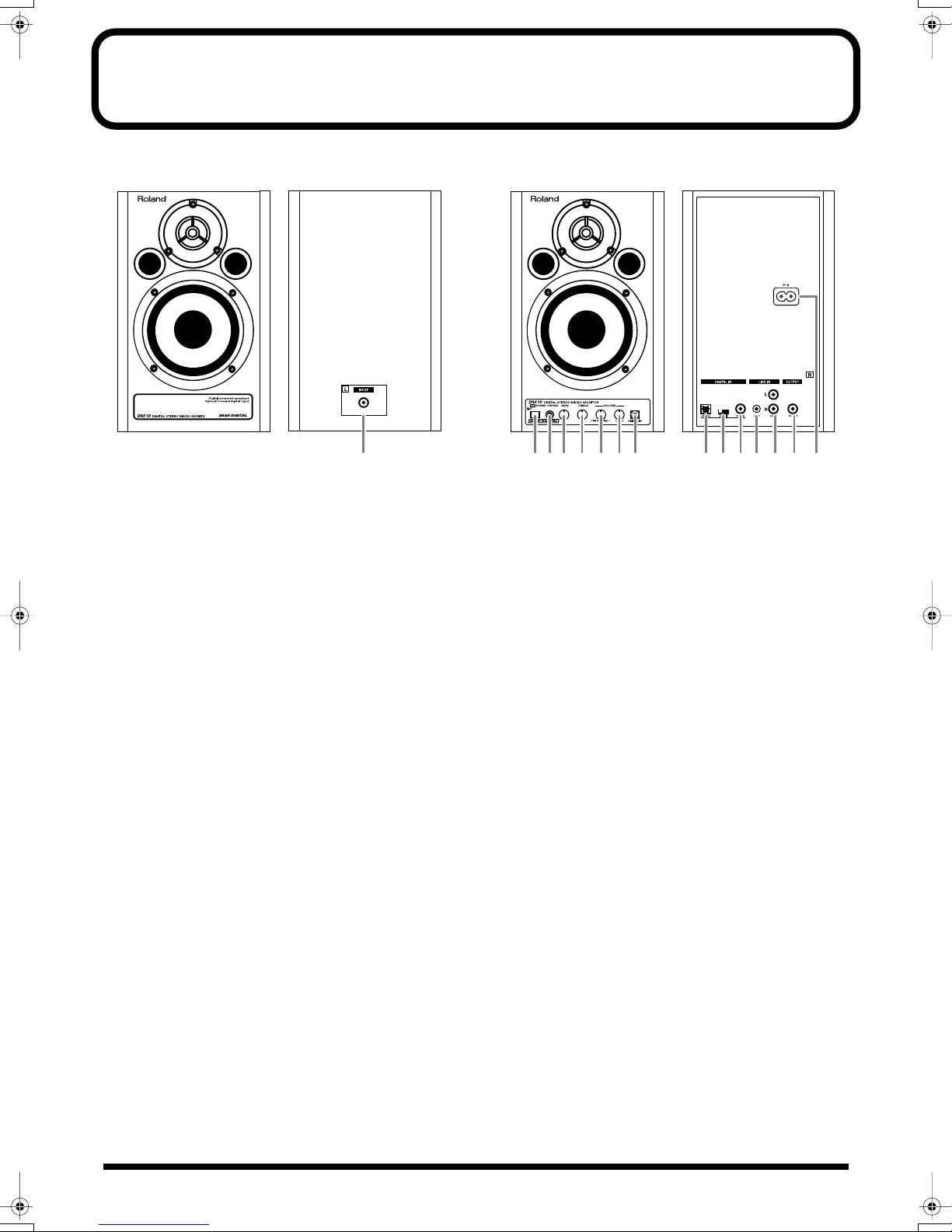
• Be sure to avoid inserting your fingers in the bass reflex ports
when transporting or moving the speakers, as your fingers may
become wedged and stuck in the ports.
DM-10_efgis 5 ページ 2004年1月8日 木曜日 午後1時59分

6
Panel Description
Left Channel
fig.2
1.
L Channel Input Jack
Connect this to L Channel Output Jack
14
on the right-
side unit. For the connection, use the included speaker
cable.
2.
POWER Switch, POWER/STANDBY Indicator
The POWER/STANDBY Indicator lights up in red
during standby, and lights up in green when power is on.
3.
PHONES Jack
When you connect headphones to this jack, no sound
will be heard from the speakers.
4.
BASS Control Knob
5.
TREBLE Control Knob
These adjust the tones of the bass and treble. Set to center
to make the tones flat.
6.
VOLUME Knob (DIGITAL/LINE 1)
This adjusts the volume of devices connected to digital
input connectors
8
,
9
,
11
, and LINE 1 Input Jack
12
.
7.
VOLUME Knob (LINE 2)
This adjusts the volume of the device connected to LINE
2 Input Jacks
13
.
8.
Digital Input Connector (Optical)
This is the digital input connector for optic-fiber cable.
* When you connect a cable to this connector, the sound of
devices connected to digital input connector
9
or
11
will
not be heard.
Right Channel
fig.3
9.
Digital Input Connector (Optical)
This is the digital input connector for optic-fiber cable.
10.
Digital Input Select Switch
This switch selects digital input connector
9
or
11
on the
rear panel. Select the connector used for the input signal.
*When you connect a cable to digital input connector
8
on
the front panel, the sound of the device connected to
8
will be heard independently of this switch.
11.
Digital Input Connector (Coaxial)
This is the digital input connector for coaxial cable.
12.
LINE 1 Input Jack (stereo mini type)
13.
LINE 2 Input Jacks (L, R) (RCA pin type)
14.
L Channel Output Jack
Connect this to L Channel Input Jack
1
on the left-side
unit.
15.
AC Inlet
Connect the included Power cord here (p. 17). Plug it
firmly in, so that the cable does not accidentally become
disconnected.
FROM RIGHT
12345678 1213 14 15
910 11
DM-10_efgis 6 ページ 2004年1月8日 木曜日 午後1時59分

7
Español Italiano Français Deutsch English
Connections
Attaching the Rubber Feet
(Included)
Precautions When Connecting
and Turning on the Power
921
• To prevent malfunction and/or damage to speakers or other
devices, always turn down the volume, and turn off the power
on all devices before making any connections.
926a
•When connection cables with resistors are used, the volume level
of equipment connected to the inputs (Input Jucks) may be low.
If this happens, use connection cables that do not contain
resistors, such as those from the Roland PCS series.
941
• Once the connections have been completed, turn on power to
your various devices in the order specified. By turning on
devices in the wrong order, you risk causing malfunction and/or
damage to speakers and other devices. (When turning the power
off, reverse this procedure.)
< Connected devices
→
DM-10 >
942
• This unit is equipped with a protection circuit. A brief
interval (a few seconds) after power up is required before
the unit will operate normally.
Connection Example
INPUT
(FROM RIGHT)
OUTPUT
(TO LEFT)
Sound Module, CD Player, MD Player, etc.
Select
* When you connect a cable to the
DIGITAL IN on the front panel, the
sound of any devices connected to
the DIGITAL INs on the rear panel
will not be heard.
Priority (*)
Front Panel
Rear Panel
DM-10_efgis 7 ページ 2004年1月8日 木曜日 午後1時59分

8
Bedienfeldbeschreibung
Linker Kanal
fig.2
1.
L-Kanal-Eingangsbuchse
Verbinden Sie diese Buchse mit der L-Kanal-
Ausgangsbuchse
14
der Einheit auf der rechten Seite.
Verwenden Sie für den Anschluss das beiliegende
Lautsprecherkabel.
2.
POWER-Schalter, POWER/STANDBY-Anzeige
Die POWER/STANDBY-Anzeige leuchtet im Standby-
Betrieb rot. Im Netzbetrieb leuchtet diese Anzeige grün.
3.
PHONES-Buchse
Wenn Sie an diese Buchse Kopfhörer anschließen, hören
Sie keinen Sound aus den Lautsprechern.
4.
BASS-Drehknopf
5.
TREBLE-Drehknopf
Mit diesen Bedienelementen werden Bass und Treble
reguliert. Drehen Sie die Drehknöpfe bis zur Mitte, um
einen tiefen Ton zu erzeugen.
6.
VOLUME-Schaltknopf (DIGITAL/LINE 1)
Dieser Schaltknopf passt die Lautstärke der Geräte an,
die mit den Digitaleingabe-Anschlüssen
8
,
9
,
11
, sowie
mit LINE 1-Eingangsbuchse
12
verbunden sind.
7.
VOLUME-Schaltknopf (LINE 2)
Stellt die Lautstärke der Geräte ein, die an den LINE 2-
Eingangsbuchsen
13
angeschlossen sind.
8.
Anschluss Digitaleingabe (optisch)
Dies ist der Digitaleingabe-Anschluss für faseroptische
Kabel.
* Wenn Sie mit diesem Anschluss ein Kabel verbinden,
hören Sie aus den Geräten, die an den Digitaleingabe-
Anschluss
9
oder
11
angeschlossen sind, keinen Sound.
Rechter Kanal
fig.3
9.
Anschluss Digitaleingabe (optisch)
Dies ist der Digitaleingabe-Anschluss für faseroptische
Kabel.
10.
Digitaleingabe-Auswahlschalter
Dieser Schalter wählt den Digitaleingabe-Anschluss
9
oder
11
auf der Rückseite aus. Wählen Sie den
Anschluss, der für das Input-Signal verwendet wird.
* Wenn Sie ein Kabel mit dem Digitaleingabe-Anschluss
8
auf der Vorderseite verbinden, hören Sie den Sound des
Geräts, das mit
8
verbunden ist, unabhängig von diesem
Schalter.
11.
Anschluss Digitaleingabe (koaxial)
Dies ist der Digitaleingabe-Anschluss für Koaxialkabel.
12.
LINE 1-Eingangsbuchse (Stereo Mini)
13.
LINE 2-Eingangsbuchsen (L, R) (RCA-Stift)
14.
L-Kanal-Ausgangsbuchse
Verbinden Sie diese Buchse mit der L-Kanal-
Eingangsbuchse
1
der Einheit auf der linken Seite.
15.
AC-Einlass
Schließen Sie hier das beiliegende Netzkabel an (s. 17).
Stecken Sie das Kabel fest ein, damit es nicht
versehentlich vom Anschluss getrennt werden kann.
FROM RIGHT
12345678 1213 14 15
910 11
DM-10_efgis 8 ページ 2004年1月8日 木曜日 午後1時59分

9
Español Italiano Français Deutsch English
Anschlüsse
Anschliessen der
Gummibeine (in der Packung)
Vorsichtsmaßnahmen beim
Anschließen des Netzkabels
und beim Einschalten
921
• Um Fehlfunktionen und/oder Schäden an Lautsprechern
oder anderen Geräten zu verhindern, reduzieren Sie stets
die Lautstärke und schalten alle Geräte ab, bevor Sie die
Verbindungen einrichten.
926 modify
• Die Verwendung von Anschlusskabeln mit Widerstand
kann der Grund für eine zu geringe Lautstärke sein.
Verwenden Sie ein Anschlusskabel, das keinen
Widerstand enthält.
941
• Nachdem die Anschlüsse fertig gestellt wurden, schalten
Sie die verschiedenen Geräte in der angegebenen
Reihenfolge ein. Wenn Sie die Geräte in der falschen
Reihenfolge einschalten, besteht die Gefahr von
Fehlfunktionen und/oder Schäden an Lautsprechern und
anderen Geräten. (Gehen Sie beim Ausschalten der Geräte
in der umgekehrten Reihenfolge vor).
< Angeschlossene Geräte
→
DM-10>
943
• Vergewissern Sie sich stets, dass die Lautstärke reduziert
wurde, bevor Sie das Gerät einschalten. Beim Einschalten
wird eventuell auch dann Sound ausgegeben, wenn der
Lautstärkeregler ganz zurückgestellt wurde. Das ist
jedoch normal und kein Anzeichen für eine Fehlfunktion.
Anschluss-Beispiel
INPUT
(FROM RIGHT)
OUTPUT
(TO LEFT)
Sound Module, CD Player, MD Player, etc.
Select
* When you connect a cable to the
DIGITAL IN on the front panel, the
sound of any devices connected to
the DIGITAL INs on the rear panel
will not be heard.
Priority (*)
Front Panel
Rear Panel
INPUT
(VON RECHTS)
OUTPUT
(NACH LINKS)
Soundmodul, CD-Player, MD-Gerät, etc.
Rückseite
Vorderseite
Priorität(*) Auswahl
* Wenn Sie ein Kabel mitDIGITAL
IN auf der Vorderseite verbinden,
ist der Klang aller Geräte, die an
DIGITAL IN-Anschlüsse auf der
Rückseite angeschlossen sind
nicht wahrnehmbar.
DM-10_efgis 9 ページ 2004年1月8日 木曜日 午後1時59分

10
Description
Canal gauche
fig. 2
1.
Prise d'entrée canal L (G)
Connectez à la prise de sortie du canal L
14
sur la droite
de l'appareil. Pour la connexion, utilisez le câble pour
enceintes inclus.
2.
Commutateur POWER, voyant POWER/STANDBY
Le voyant POWER/STANDBY est rouge en mode veille,
et vert lorsque l'appareil est alimenté.
3.
Prise PHONES (casque)
Si vous reliez un casque à cette prise, le son ne passera
plus sur les enceintes.
4.
Bouton BASS
5.
Bouton TREBLE
Ils servent à régler les basses et les aiguës. Pour obtenir
un réglage neutre, mettre les boutons en position
médiane.
6.
Bouton VOLUME (DIGITAL/LINE 1)
Il sert à régler le volume des appareils reliés aux
connecteurs d'entrée numérique
8
,
9
,
11
, ainsi qu'à la
prise d'entrée LINE 1
12
.
7.
Bouton VOLUME (LINE 2)
Ce bouton ajuste le volume de l'appareil connecté aux
prises d'entrée LINE 2
13
.
8.
Connecteur d’entrée numérique (optique)
C'est le connecteur d'entrée numérique pour câble en
fibre optique.
* Si vous reliez un câble à ce connecteur, le son des
appareils reliés au connecteur d'entrée numérique
9
ou
11
sera désactivé.
Canal droit
fig. 3
9.
Connecteur d’entrée numérique (optique)
Connecteur d'entrée numérique pour câble en fibre
optique.
10.
Commutateur Entrée numérique
Ce commutateur sert à sélectionner le connecteur
d'entrée numérique
9
ou
11
sur la face arrière.
Sélectionnez le connecteur utilisé pour le signal d'entrée.
* Si vous reliez un câble au connecteur d'entrée numérique
8
sur la face avant, le son de l'appareil relié à
8
sera
audible, indépendamment de ce commutateur.
11.
Connecteur d’entrée numérique (coaxial)
C'est le connecteur d'entrée numérique pour câble
coaxial.
12.
Prise d'entrée LINE 1 (type mini-stéréo)
13.
Prises d'entrée LINE 2 (L, R) (type RCA)
14.
Prise de sortie canal L (G)
Connectez à la prise de sortie du canal L
1
sur la gauche
de l'appareil.
15.
Connecteur AC IN
Branchez ici le cordon d'alimentation (p. 17). Enfichez-le
fermement, pour éviter que le cordon ne soit déconnecté
par accident.
FROM RIGHT
12345678 1213 14 15
910 11
DM-10_efgis 10 ページ 2004年1月8日 木曜日 午後1時59分

11
Español Italiano Français Deutsch English
Connexions
Fixer les pieds en caoutchouc
(inclus)
Précautions à prendre lors
des connexions et de la mise
sous tension
921
• Afin d’éviter un mauvais fonctionnement et/ou
d’endommager les enceintes et autres périphériques,
diminuez toujours le volume et mettez toujours les
périphériques hors tension avant d’effectuer une
connexion.
926 modify
• L'utilisation d'un câble à résistance peut entraîner une
perte de niveau sonore. Utilisez des câbles ne contenant
pas de résistance.
941
•Quand les connexions sont effectuées, mettez sous tension
les différents appareils dans l’ordre spécifié. Ne pas
respecter cet ordre peut entraîner des dysfonctionnements
et/ou endommager les enceintes ou tout autre appareil.
(Lors de la mise hors tension, suivez la procédure inverse.)
<Appareils connectés
→
DM-10>
943
• Baissez toujours le volume avant la mise sous tension.
Même avec le volume à zéro, il se peut que vous entendiez
des sons lors de la mise sous tension, mais cela ne signifie
rien d'anormal.
Exemple de connexion
INPUT
(FROM RIGHT)
OUTPUT
(TO LEFT)
Sound Module, CD Player, MD Player, etc.
Select
* When you connect a cable to the
DIGITAL IN on the front panel, the
sound of any devices connected to
the DIGITAL INs on the rear panel
will not be heard.
Priority (*)
Front Panel
Rear Panel
ENTREE
(DE LA DROITE)
SORTIE (VERS
LA GAUCHE)
Module de sons, Lecteur CD, Lecteur MD, etc.
Face avant
Face arrière
Priorité(*) Sélection
* Si vous connectez un câble sur
DIGITAL IN en face avant, le son des
appareils connectés sur les prises
DIGITAL IN en face arrière ne sera
pas audible.
DM-10_efgis 11 ページ 2004年1月8日 木曜日 午後1時59分

12
Descrizione del pannello
Canale sinistro
fig.2
1.
Presa d’ingresso canale sinistro
Collegare alla presa d’uscita del canale sinistro
14
sul
lato destro dell’apparecchio. Per effettuare il
collegamento, utilizzare il cavo per altoparlanti in
dotazione.
2.
Interruttore POWER, Indicatore POWER/STANDBY
L’indicatore POWER/STANDBY diventa rosso in
standby e verde quando l’apparecchio è acceso.
3.
Presa PHONES
Se si collegano le cuffie a questa presa, non verrà emesso
alcun suono dagli altoparlanti.
4.
Manopola BASS
5.
Manopola TREBLE
Regolano i bassi e gli acuti. Regolare al centro per
uniformare il suono.
6.
Manopola VOLUME (DIGITAL/LINE 1)
Regola il volume dei dispositivi collegati ai connettori
d’ingresso digitale
8
,
9
,
11
e alla presa d’ingresso LINE
1
12
.
7.
Manopola VOLUME (LINE 2)
Questo regola il volume dei sistemi collegati a prese
díingresso LINE 2
13
.
8.
Connettore di ingresso digitale (ottico)
Connettore d’ingresso digitale per il cavo a fibre ottiche.
*Se un cavo viene collegato a questo connettore, i suoni dei
dispositivi collegati al connettore d’ingresso digitale
9
o
11
non saranno udibili.
Canale destro
fig.3
9.
Connettore di ingresso digitale (ottico)
Connettore d’ingresso digitale per il cavo a fibre ottiche.
10.
Interruttore di selezione ingresso digitale
Questo interruttore seleziona il connettore di ingresso
digitale
9
o
11
sul pannello posteriore. Selezionare il
connettore utilizzato per il segnale in entrata.
* Se si collega un cavo al connettore d’ingresso digitale
8
sul pannello frontale, i suoni del dispositivo collegato a
8
saranno udibili indipendentemente dalla posizione di
questo interruttore.
11.
Connettore di ingresso digitale (coassiale)
Connettore d’ingresso digitale per il cavo coassiale.
12.
Presa d’ingresso LINE 1 (tipo mini stereo)
13.
Prese d’ingresso LINE 2 (L, R) (pin tipo RCA)
14.
Presa d’uscita canale sinistro
Collegare alla presa d’ingresso del canale sinistro
1
sul
lato sinistro dell’apparecchio.
15.
Presa AC
Collegare a questa presa il cavo di alimentazione in
dotazione (p. 17). Inserirlo a fondo per evitare che si
scolleghi accidentalmente.
FROM RIGHT
12345678 1213 14 15
910 11
DM-10_efgis 12 ページ 2004年1月8日 木曜日 午後1時59分

13
Español Italiano Français Deutsch English
Collegamenti
Montare i Piedini in Gomma
(Inclusi)
Precauzioni durante i
collegamenti e l’accensione
921
• Per evitare malfunzionamenti e/o danni ai diffusori o ad
altri dispositivi, abbassare sempre il volume e accertarsi
che tutti gli apparecchi non siano alimentati prima di
effettuare i collegamenti.
926 modify
• L’uso di un cavo provvisto di un resistore potrebbe
risultare in un livello audio basso. Utilizzare un cavo di
collegamento senza resistore.
941
• Una volta terminati i collegamenti, accendere i vari
dispositivi nell’ordine indicato. Se i dispositivi vengono
accesi nell’ordine sbagliato, si rischia di provocare
malfunzionamenti e/o danni ai diffusori e agli altri
dispositivi. (Seguire la procedura al contrario nella fase di
spegnimento.)
< Dispositivi collegati
→
DM-10>
943
• Prima di accendere gli apparecchi, accertarsi che il livello
del volume sia al minimo. Si potrebbero sentire comunque
dei suoni all’accensione, anche se il volume è al minimo; è
normale e non c’è motivo di preoccuparsi.
Esempio di collegamenti
INPUT
(FROM RIGHT)
OUTPUT
(TO LEFT)
Sound Module, CD Player, MD Player, etc.
Select
* When you connect a cable to the
DIGITAL IN on the front panel, the
sound of any devices connected to
the DIGITAL INs on the rear panel
will not be heard.
Priority (*)
Front Panel
Rear Panel
INGRESSO
(DA DESTRA)
USCITA
(A SINISTRA)
Pannello
frontale
Pannello
posteriore
Priorità(*) Sele-
zionare
* Se si collega un cavo nella presa
DIGITAL IN sul pannello frontale,
non si potrà sentire l’audio emesso
dagli apparecchi collegati alle prese
DIGITAL IN.
Modulo sonoro, lettore CD, lettore MD, ecc.
DM-10_efgis 13 ページ 2004年1月8日 木曜日 午後1時59分

14
Descripción del panel
Canal izquierdo
Ilustración 2
1.
Jack de entrada del canal izquierdo
Conéctelo al jack de salida del canal izquierdo
14
que se
encuentra en el lado derecho de la unidad. Para la
conexión, utilice el cable del altavoz que viene incluido.
2.
Interruptor POWER, Indicador POWER/STANDBY
El indicador POWER/STANDBY muestra una luz de
color rojo cuando la unidad se encuentra en modo de
espera y una luz de color verde cuando está encendida.
3.
Jack de los auriculares
Cuando conecte los auriculares a este jack, los altavoces
no emitirán ningún sonido.
4.
Control BASS
5.
Control TREBLE
Estos botones ajustan el tono de los bajos y los agudos.
Cóloquelos en el centro para que los tonos queden
nivelados.
6.
Control VOLUME (DIGITAL/LÍNEA 1)
Ajusta el volumen de los aparatos conectados a los
conectores de entrada digital
8
,
9
,
11
, y al jack de
entrada de la LÍNEA 1
12
.
7.
Control VOLUME (LÍNEA 2)
Esto ajusta el volumen del dispositivo conectado a los
enchufes
13
de la LÍNEA 2.
8.
Conector de entrada digital (Optical)
Este es el conector de entrada digital para el cable de
fibra óptica.
*Cuando conecte un cable a este conector, no se podrá oir el
sonido de los aparatos conectados al conector de entrada
digital
9
o
11
.
Canal derecho
Ilustración.3
9.
Conector de entrada digital (Optical)
Este es el conector de entrada digital para el cable de
fibra óptica.
10.
Interruptor de selección de entrada digital
Este interruptor selecciona el conector de entrada digital
9
o
11
en el panel posterior. Seleccione el conector que
se utiliza para la señal de entrada.
* Cuando conecta un cable al conector de entrada digital
8
en el panel frontal, se podrá oir el sonido del aparato
conectado a
8
independientemente de este interruptor.
11.
Conector de entrada digital (Coaxial)
Este es el conector de entrada digital para el cable
coaxial.
12.
Jack de entrada de la LÍNEA 1 (stereo mini type)
13.
Jacks de entrada de la LÍNEA 2 (Izquierda, Derecha)
(tipo de patilla RCA)
Este es el conector de entrada digital para el cable de
fibra óptica.
14.
Jack de salida del canal izquierdo
Conéctelo al jack de entrada del canal izquierdo
1
que se
encuentra en el lado izquierdo de la unidad.
15.
Entrada CA
Conecte aquí el cable de alimentación (Paginas 17).
Enchúfelo de modo que el cable no se pueda desconectar
FROM RIGHT
12345678 1213 14 15
910 11
DM-10_efgis 14 ページ 2004年1月8日 木曜日 午後1時59分

15
Español Italiano Français Deutsch English
Conexiones
Incluye los pies de goma
Precauciones que debe tener
en cuenta cuando conecte y
encienda la unidad
921
•Para evitar anomalías en el funcionamiento o daños en los
altavoces u otros aparatos, baje siempre el volumen y
apague todos los aparatos antes de realizar cualquier
conexión.
926 modicar
• Si utiliza un cable que posea un reostato, el nivel de
sonido puede bajar. Utilice un cable de conexión que no
contenga un reostato.
941
• Una vez completadas las conexiones, encienda los
diferentes aparatos en el orden especificado. Si enciende
los aparatos en un orden equivocado, puede causar
anomalías en el funcionamiento o daños en los altavoces y
otros aparatos. (Cuando apague el sistema, siga estas
instrucciones en el orden inverso)
< Aparatos conectados
→
DM-10>
943
• Asegúrese siempre de tener bajado el volumen antes de
encender la unidad. Aunque tenga el volumen
completamente bajado, puede oir algún sonido al
encender la unidad pero esto es algo normal y no indica
un mal funcionamiento de la misma.
Ejemplo de conexión
INPUT
(FROM RIGHT)
OUTPUT
(TO LEFT)
Sound Module, CD Player, MD Player, etc.
Select
* When you connect a cable to the
DIGITAL IN on the front panel, the
sound of any devices connected to
the DIGITAL INs on the rear panel
will not be heard.
Priority (*)
Front Panel
Rear Panel
ENTRADA (DESDE
LA DERECHA)
SALIDA (A LA
IZQUIERDA)
Panel
frontal
Panel posterior
Prioridad(*) Selec-
ción
* Cuando conecta un cable a la
DIGITAL IN (Entrada digital) del
panel frontal, no se podrá escuchar el
sonido de ningún aparato que esté
conectado a la o las DIGITAL IN
(Entradas digitales) del panel
posterior.
Módulo de sonido, reproductor de CD, reproductor de MD, etc.
DM-10_efgis 15 ページ 2004年1月8日 木曜日 午後1時59分

16
Specifications
Rated Power Output
20 W (10 W + 10 W)
Speaker Unit
Woofer: 9.2 cm /
3-5/8” (Magnetically-Shielded)
Tweeter: 5 cm /
2” (Magnetically-Shielded)
Frequency Range
45 Hz to 35 kHz
Nominal Input Level
Line: -10 dBu
Stereo: -10 dBu
Input Impedance
18 k ohms
Controls
< R Channel >
BASS Control Knob
TREBLE Control Knob
VOLUME Knob x 2
• VOLUME 1 (digital inputs + stereo mini)
• VOLUME 2 (RCA phono)
POWER Switch
Digital Input Select SwitchIndicator
Power/Standby Indicator
Connectors
< R Channel >
Front: PHONES Jack (stereo miniature phone type)
Optical Input Connector
Rear: LINE 1 Jack (stereo miniature phone type)
LINE 2 Jacks (L, R) (RCA phono type)
L Channel Output Jack (RCA phono type)
Optical Input Connecto
Coaxial Input Connector
< L Channel >
Rear: L Channel Input Jack (RCA phono type)
Digital Input Section
Sampling Rate: 32/44.1/48/96 kHz, 24-bit
D/A Converter: 24-bit
Enclosure
2 way Bass-reflex type (Wooden Cabinet)
Power Supply
AC 117 V, AC 230 V or AC 240 V
Power Consumption
230 mA (AC 117 V)
120 mA (AC 230 V)
110 mA (AC 240 V)
Dimensions
156 (W) x 197 (D) x 238 (H) mm
6-3/16 (W) x 7-13/16 (D) x 9-3/8 (H) inches
Weight
< R Channel >
3.5 kg / 7 lbs 12 oz
< L Channel >
2.3 kg / 5 lbs 2 oz
Accessories
Owner’s Manual
Conversion Cable
(stereo miniature phone type
↔
RCA phono type)
Speaker Cable (RCA phono type)
Power Cord
*0dBu = 0.775 V rms
* In the interest of product improvement, the specifications and/
or appearance of this unit are subject to change without prior
notice.
DM-10_efgis 16 ページ 2004年1月8日 木曜日 午後1時59分

17
For 230 V (English)
This box contains continental and British power cables. Please select the correct type for your country.
Für 230 V (Deutsch)
Diese Packung beinhaltet europäische und britische Netzkabel. Bitte suchen Sie sich die richtige Variante für Ihr Land aus.
Pour 230 V (Français)
Cette boite contient des alimentations anglaises ou continentales. Merci de choisir l’alimentation appropriée de votre pays.
Per 230 V (Italiano)
La confezione contiene alimentatori con spina europea e Inglese. Scegliete quella adatta alla Vostra nazione.
Para 230 V (Español)
Esta caja contiene cables de corriente continentales y británicos. Por favor seleccione el tipo correcto para su país.
Application of AC230 V
Power Cord
for UK
except for UK
DM-10_efgis 17 ページ 2004年1月8日 木曜日 午後1時59分

18
DM-10_efgis 18 ページ 2004年1月8日 木曜日 午後1時59分

19
This product complies with the requirements of European Directives EMC 89/336/EEC and LVD 73/23/EEC.
For EU Countries
For Canada
This Class B digital apparatus meets all requirements of the Canadian Interference-Causing Equipment Regulations.
Cet appareil numérique de la classe B respecte toutes les exigences du Règlement sur le matériel brouilleur du Canada.
NOTICE
AVIS
For the USA
FEDERAL COMMUNICATIONS COMMISSION
RADIO FREQUENCY INTERFERENCE STATEMENT
This equipment has been tested and found to comply with the limits for a Class B digital device, pursuant to Part 15 of the
FCC Rules. These limits are designed to provide reasonable protection against harmful interference in a residential
installation. This equipment generates, uses, and can radiate radio frequency energy and, if not installed and used in
accordance with the instructions, may cause harmful interference to radio communications. However, there is no guarantee
that interference will not occur in a particular installation. If this equipment does cause harmful interference to radio or
television reception, which can be determined by turning the equipment off and on, the user is encouraged to try to correct the
interference by one or more of the following measures:
– Reorient or relocate the receiving antenna.
– Increase the separation between the equipment and receiver.
– Connect the equipment into an outlet on a circuit different from that to which the receiver is connected.
– Consult the dealer or an experienced radio/TV technician for help.
This device complies with Part 15 of the FCC Rules. Operation is subject to the following two conditions:
(1) This device may not cause harmful interference, and
(2) This device must accept any interference received, including interference that may cause undesired operation.
Unauthorized changes or modification to this system can void the users authority to operate this equipment.
This equipment requires shielded interface cables in order to meet FCC class B Limit.
DM-10_efgis 19 ページ 2004年1月8日 木曜日 午後1時59分

03567501 1KG
Information
When you need repair service, call your nearest Roland Service Center or authorized Roland distributor in your country as
shown below.
As of November 1, 2003 (Roland)
ARGENTINA
Instrumentos Musicales S.A.
Av.Santa Fe 2055
(1123) Buenos Aires
ARGENTINA
TEL: (011) 4508-2700
BRAZIL
Roland Brasil Ltda
Rua San Jose, 780 Sala B
Parque Industrial San Jose
Cotia - Sao Paulo - SP, BRAZIL
TEL: (011) 4615 5666
MEXICO
Casa Veerkamp, s.a. de c.v.
Av. Toluca No. 323, Col. Olivar
de los Padres 01780 Mexico D.F.
MEXICO
TEL: (55) 5668-6699
PANAMA
SUPRO MUNDIAL, S.A.
Boulevard Andrews, Albrook,
Panama City, REP. DE PANAMA
TEL: 315-0101
U. S. A.
Roland Corporation U.S.
5100 S. Eastern Avenue
Los Angeles, CA 90040-2938,
U. S. A.
TEL: (323) 890 3700
VENEZUELA
Musicland Digital C.A.
Av. Francisco de Miranda,
Centro Parque de Cristal, Nivel
C2 Local 20 Caracas
VENEZUELA
TEL: (212) 285-8586
AUSTRALIA
Roland Corporation
Australia Pty., Ltd.
38 Campbell Avenue
Dee Why West. NSW 2099
AUSTRALIA
TEL: (02) 9982 8266
NEW ZEALAND
Roland Corporation Ltd.
32 Shaddock Street, Mount Eden,
Auckland, NEW ZEALAND
TEL: (09) 3098 715
HONG KONG
Tom Lee Music Co., Ltd.
Service Division
22-32 Pun Shan Street, Tsuen
Wan, New Territories,
HONG KONG
TEL: 2415 0911
Parsons Music Ltd.
8th Floor, Railway Plaza, 39
Chatham Road South, T.S.T,
Kowloon, HONG KONG
TEL: 2333 1863
INDIA
Rivera Digitec (India) Pvt. Ltd.
409, Nirman Kendra Mahalaxmi
Flats Compound Off. Dr. Edwin
Moses Road, Mumbai-400011,
INDIA
TEL: (022) 2493 9051
INDONESIA
PT Citra IntiRama
J1. Cideng Timur No. 15J-150
Jakarta Pusat
INDONESIA
TEL: (021) 6324170
MALAYSIA
BENTLEY MUSIC SDN BHD
140 & 142, Jalan Bukit Bintang
55100 Kuala Lumpur,MALAYSIA
TEL: (03) 2144-3333
PHILIPPINES
G.A. Yupangco & Co. Inc.
339 Gil J. Puyat Avenue
Makati, Metro Manila 1200,
PHILIPPINES
TEL: (02) 899 9801
SINGAPORE
Swee Lee Company
150 Sims Drive,
SINGAPORE 387381
TEL: 6846-3676
TAIWAN
ROLAND TAIWAN
ENTERPRISE CO., LTD.
Room 5, 9fl. No. 112 Chung Shan
N.Road Sec.2, Taipei, TAIWAN,
R.O.C.
TEL: (02) 2561 3339
THAILAND
Theera Music Co. , Ltd.
330 Verng NakornKasem, Soi 2,
Bangkok 10100, THAILAND
TEL: (02) 2248821
BAHRAIN
Moon Stores
No.16, Bab Al Bahrain Avenue,
P.O.Box 247, Manama 304,
State of BAHRAIN
TEL: 211 005
VIETNAM
Saigon Music
Suite DP-8
40 Ba Huyen Thanh Quan Street
Hochiminh City, VIETNAM
Tel: (08) 930-1969
JORDAN
AMMAN Trading Agency
245 Prince Mohammad St.,
Amman 1118, JORDAN
TEL: (06) 464-1200
KUWAIT
Easa Husain Al Yousifi Est.
Abdullah Salem Street,
Safat, KUWAIT
TEL: 243-6399
LEBANON
Chahine S.A.L.
Gerge Zeidan St., Chahine Bldg.,
Achrafieh, P.O.Box: 16-5857
Beirut, LEBANON
TEL: (01) 20-1441
QATAR
Al Emadi Co. (Badie Studio
& Stores)
P.O. Box 62, Doha, QATAR
TEL: 4423-554
SAUDI ARABIA
aDawliah Universal
Electronics APL
Corniche Road, Aldossary Bldg.,
1st Floor, Alkhobar,
SAUDI ARABIA
P.O.Box 2154, Alkhobar 31952
SAUDI ARABIA
TEL: (03) 898 2081
TURKEY
Ant Muzik Aletleri Ithalat
Ve Ihracat Ltd Sti
Siraselviler Caddesi Siraselviler
Pasaji No:74/20
Taksim - Istanbul, TURKEY
TEL: (0212) 2499324
U.A.E.
Zak Electronics & Musical
Instruments Co. L.L.C.
Zabeel Road, Al Sherooq Bldg.,
No. 14, Grand Floor, Dubai, U.A.E.
TEL: (04) 3360715
EGYPT
Al Fanny Trading Office
9, EBN Hagar A1 Askalany Street,
ARD E1 Golf, Heliopolis,
Cairo 11341, EGYPT
TEL: 20-2-417-1828
REUNION
Maison FO - YAM Marcel
25 Rue Jules Hermann,
Chaudron - BP79 97 491
Ste Clotilde Cedex,
REUNION ISLAND
TEL: (0262) 218-429
SOUTH AFRICA
That Other Music Shop
(PTY) Ltd.
11 Melle St., Braamfontein,
Johannesbourg, SOUTH AFRICA
P.O.Box 32918, Braamfontein 2017
Johannesbourg, SOUTH AFRICA
TEL: (011) 403 4105
Paul Bothner (PTY) Ltd.
17 Werdmuller Centre,
Main Road, Claremont 7708
SOUTH AFRICA
P.O.BOX 23032, Claremont 7735,
SOUTH AFRICA
TEL: (021) 674 4030
CYPRUS
Radex Sound Equipment Ltd.
17, Diagorou Street, Nicosia,
CYPRUS
TEL: (022) 66-9426
DENMARK
Roland Scandinavia A/S
Nordhavnsvej 7, Postbox 880,
DK-2100 Copenhagen
DENMARK
TEL: 3916 6200
FRANCE
Roland France SA
4, Rue Paul Henri SPAAK,
Parc de l'Esplanade, F 77 462 St.
Thibault, Lagny Cedex FRANCE
TEL: 01 600 73 500
FINLAND
Roland Scandinavia As,
Filial Finland
Elannontie 5
FIN-01510 Vantaa, FINLAND
TEL: (0)9 68 24 020
GERMANY
Roland Elektronische
Musikinstrumente HmbH.
Oststrasse 96, 22844 Norderstedt,
GERMANY
TEL: (040) 52 60090
GREECE
STOLLAS S.A.
Music Sound Light
155, New National Road
Patras 26442, GREECE
TEL: 2610 435400
HUNGARY
Roland East Europe Ltd.
Warehouse Area ‘DEPO’ Pf.83
H-2046 Torokbalint, HUNGARY
TEL: (23) 511011
IRELAND
Roland Ireland
G2 Calmount Park, Calmount
Avenue, Dublin 12
Republic of IRELAND
TEL: (01) 4294444
ITALY
Roland Italy S. p. A.
Viale delle Industrie 8,
20020 Arese, Milano, ITALY
TEL: (02) 937-78300
NORWAY
Roland Scandinavia Avd.
Kontor Norge
Lilleakerveien 2 Postboks 95
Lilleaker N-0216 Oslo
NORWAY
TEL: 2273 0074
POLAND
MX MUSIC SP.Z.O.O.
UL. Gibraltarska 4.
PL-03664 Warszawa POLAND
TEL: (022) 679 44 19
PORTUGAL
Tecnologias Musica e Audio,
Roland Portugal, S.A.
Cais Das Pedras, 8/9-1 Dto
4050-465 PORTO
PORTUGAL
TEL: (022) 608 00 60
RUSSIA
MuTek
3-Bogatyrskaya Str. 1.k.l
107 564 Moscow, RUSSIA
TEL: (095) 169 5043
SPAIN
Roland Electronics
de España, S. A.
Calle Bolivia 239, 08020
Barcelona, SPAIN
TEL: (93) 308 1000
SWITZERLAND
Roland (Switzerland) AG
Landstrasse 5, Postfach,
CH-4452 Itingen,
SWITZERLAND
TEL: (061) 927-8383
SWEDEN
Roland Scandinavia A/S
SWEDISH SALES OFFICE
Danvik Center 28, 2 tr.
S-131 30 Nacka SWEDEN
TEL: (0)8 702 00 20
UKRAINE
TIC-TAC
Mira Str. 19/108
P.O. Box 180
295400 Munkachevo, UKRAINE
TEL: (03131) 414-40
UNITED KINGDOM
Roland (U.K.) Ltd.
Atlantic Close, Swansea
Enterprise Park, SWANSEA
SA7 9FJ,
UNITED KINGDOM
TEL: (01792) 702701
KOREA
Cosmos Corporation
1461-9, Seocho-Dong,
Seocho Ku, Seoul, KOREA
TEL: (02) 3486-8855
AUSTRIA
Roland Austria GES.M.B.H.
Siemensstrasse 4, P.O. Box 74,
A-6063 RUM, AUSTRIA
TEL: (0512) 26 44 260
BELGIUM/HOLLAND/
LUXEMBOURG
Roland Benelux N. V.
Houtstraat 3, B-2260, Oevel
(Westerlo) BELGIUM
TEL: (014) 575811
CZECH REP.
K-AUDIO
Kardasovska 626.
CZ-198 00 Praha 9,
CZECH REP.
TEL: (2) 666 10529
AFRICA
CHILE
Comercial Fancy S.A.
Rut.: 96.919.420-1
Nataniel Cox #739, 4th Floor
Santiago - Centro, CHILE
TEL: (02) 688-9540
URUGUAY
Todo Musica S.A.
Francisco Acuna de Figueroa 1771
C.P.: 11.800
Montevideo, URUGUAY
TEL: (02) 924-2335
EUROPE
AUSTRALIA/
NEW ZEALAND
ASIA
CENTRAL/LATIN
AMERICA
NORTH AMERICA
MIDDLE EAST
AFRICA
EL SALVADOR
OMNI MUSIC
75 Avenida Norte y Final
Alameda Juan Pablo ,
Edificio No.4010 San Salvador,
EL SALVADOR
TEL: 262-0788
ROMANIA
FBS LINES
Piata Libertatii 1,
535500 Gheorgheni, ROMANIA
TEL: (266) 364 609
PARAGUAY
Distribuidora De
Instrumentos Musicales
J.E. Olear y ESQ. Manduvira
Asuncion PARAGUAY
TEL: (021) 492-124
COSTA RICA
JUAN Bansbach
Instrumentos Musicales
Ave.1. Calle 11, Apartado 10237,
San Jose, COSTA RICA
TEL: 258-0211
CRISTOFORI MUSIC PTE
LTD
Blk 3014, Bedok Industrial Park E,
#02-2148, SINGAPORE 489980
TEL: 6243-9555
IRAN
MOCO, INC.
No.41 Nike St., Dr.Shariyati Ave.,
Roberoye Cerahe Mirdamad
Tehran, IRAN
TEL: (021) 285-4169
ISRAEL
Halilit P. Greenspoon &
Sons Ltd.
8 Retzif Ha'aliya Hashnya St.
Tel-Aviv-Yafo ISRAEL
TEL: (03) 6823666
SYRIA
Technical Light & Sound
Center
Khaled Ebn Al Walid St.
Bldg. No. 47, P.O.BOX 13520,
Damascus, SYRIA
TEL: (011) 223-5384
CANADA
Roland Canada Music Ltd.
(Head Office)
5480 Parkwood Way Richmond
B. C., V6V 2M4 CANADA
TEL: (604) 270 6626
Roland Canada Music Ltd.
(Toronto Office)
170 Admiral Boulevard
Mississauga On L5T 2N6
CANADA
TEL: (905) 362 9707
CHINA
Roland Shanghai Electronics
Co.,Ltd.
5F. No.1500 Pingliang Road
Shanghai 200090, CHINA
TEL: (021) 5580-0800
Roland Shanghai Electronics
Co.,Ltd.
(BEIJING OFFICE)
10F. No.18 Anhuaxili
Chaoyang District, Beijing 100011
CHINA
TEL: (010) 6426-5050
Roland Shanghai Electronics
Co.,Ltd.
(GUANGZHOU OFFICE)
2/F., No.30 Si You Nan Er Jie Yi
Xiang, Wu Yang Xin Cheng,
Guangzhou 510600, CHINA
Tel: (020) 8736-0428
DM-10_efgis 20 ページ 2004年1月8日 木曜日 午後1時59分
Other manuals for Dm-10
1
Table of contents
Other Roland Portable Speakers manuals