Safety
Combi Light MCLM-001 Installation and Operation Manual
Page 4 of 5 Ver:1.00 Rev:1 June 2021
Safety
This manual is specifically applicable to the Combi Light, LED Deck Lighting product and is
provided as a guide to its installation and use.
WARNING: Electrical Power
Make sure electrical power is isolated BEFORE starting this procedure.
x Turn power OFF at the SOURCE.
IMPORTANT: Installers and End Users must read and understand the content
of this manual before installation/use.
Installation must only be performed by someone who is properly qualified and
competent to do so in accordance with the current legislation and Electrical Wiring
Regulations of the geographical location of the installation.
x If the advice in this manual is not understood, contact Rolec for further advice
and/or training BEFORE attempting installation/operation of the equipment.
x Rolec Services Ltd cannot accept any responsibility for improper installation or any
problems arising from improper installation.
NOTE: Damage to the equipment, connected systems or to property caused by
improper installation/use are the responsibility of the installer/user.
x The information provided in this manual must ONLY be used with the model(s) listed on
page 2 of this manual.
x The information provided in this manual must NOT be used with any other product.
x The content of this manual may be updated as required.
x Do NOT use the equipment for anything other than its intended purpose.
x Do NOT modify the equipment unless specifically instructed to do so by the
manufacturer.
x Do NOT attempt to repair the equipment unless specifically instructed to do so by the
manufacturer.
x This product is electrically safe when in normal use.
x Damage to the product may render it unsafe. The product must be electrically
isolated and NOT used until appropriate remedial action has been performed.
Product Overview
MCLM-001 Installation and Operation Manual Combi Light
Ver:1.00 Rev:1 June 2021 Page 5 of 6
Safety Advice within this Manual
Rolec manuals use a system of warnings, cautions and notes.
x WARNINGS concern the safety of installers/end user and will be given before the
detail/instructions in the manual.
x CAUTIONS concern the potential for damage to the equipment and will be given
before the detail/instructions in the manual.
x NOTES are given to provide additional information and/or highlight information of
importance. They will be given either before or after the detail/instructions as
appropriate and may use different wording (such as IMPORTANT) where emphasis is
required.
Warnings, Cautions and Notes may be repeated several times as appropriate and may
be preceded by a hazard symbol.
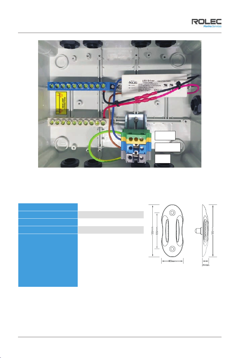
Product Overview
The Combi Light, LED Deck Lighting System is specifically designed to provide ground level,
illumination of decks, pontoons, access bridges and quaysides but is equally effective in
both domestic and business settings where attractive, unobtrusive and robust fittings are
required.
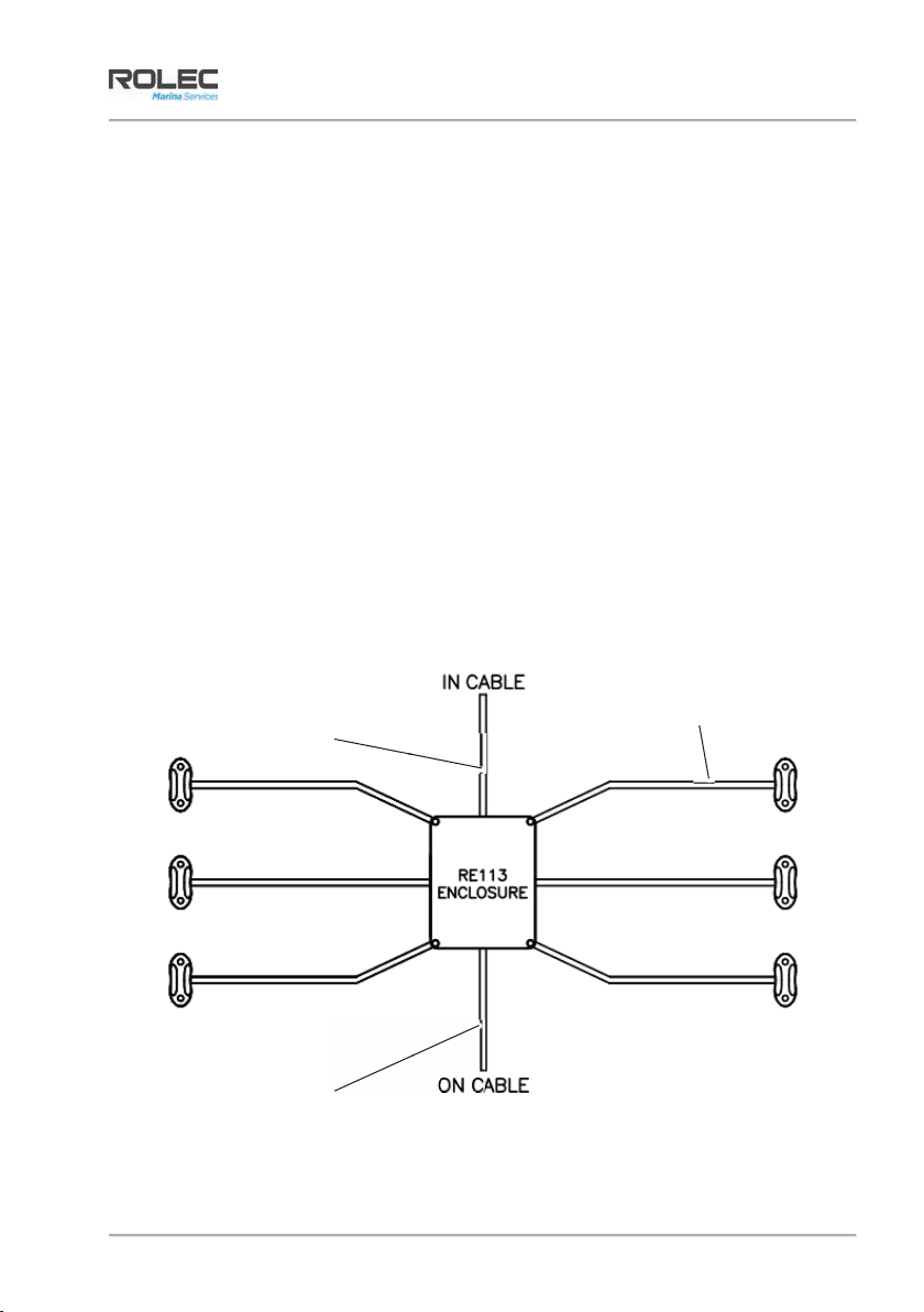
The Combi Light system comes pre-configured in 6 or 10-way looms and full looms may be
linked to a central control point in the same way as other powered systems.
Figure 1 Example of 6-Way System
Power Supply cable
(supplied by installer)
Switch cable
(supplied by installer)
10 metre lighting cable