Roller DHN 4 Series User manual

DHN EC
Montageanleitung
Mounting instructions
Instrucciones de montaje
Deckenluftkühler, beidseitig ausblasend
Dual discharge unit air cooler
Evaporadores de doble flujo
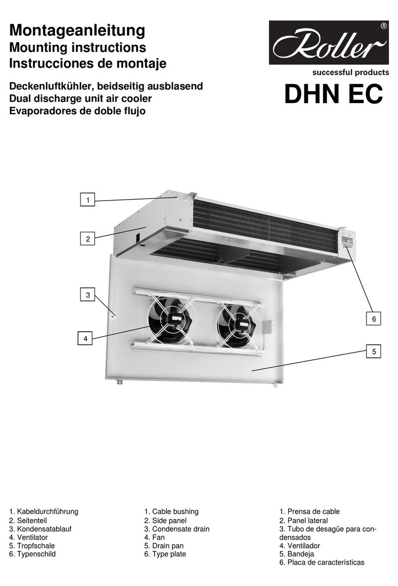
1. Kabeldurchführung
2. Seitenteil
3. Kondensatablauf
4. Ventilator
5. Tropfschale
6. Typenschild
1. Cable bushing
2. Side panel
3. Condensate drain
4. Fan
5. Drain pan
6. Type plate
1. Prensa de cable
2. Panel lateral
3. Tubo de desagüe para
condensados
4. Ventilador
5. Bandeja
6. Placa de características
5
6
2
3
1
4

2
Einbauerklärung Declaration of
incorporation Declaración del fabricante
Einbauerklärung im Sinne der EG Maschinenrichtlinie 2006/42/EG, Anhang II B
Translation of declaration of incorporation as defined by the EC machinery Directive 2006/42/EC, Annex II B
Traducción de declaración del fabricante según la Directiva de maquinaria CE 2006/42/CE, Anexo II B
Der Hersteller erklärt hiermit, dass die Bauart der
The manufacturer declares hereby that the construction of
El fabricante declara que el modelo de los
•Ventilator-Luftkühler/Forced convection unit air coolers/ Evaporadores de tiro forzado
DHN, DLK/T, FHV/T, FHVI/T, FKN/T, HVS/T, HVIS/T, SV, UV/T, UWD, VW/VM/VD, RDVN, WPV
•Ventilatorbelüfteten Verflüssiger/Forced convection air cooled refrigerant condensers/ Condensadores frigoríficos axiales
KVN
•Ventilator-Konvektoren zur Raumklimatisierung/ Fan coil units for room airconditioning/ Ventilo-convectores para aire acondicionado/
HKN/S/D, HKNI/L, HKNDI/L
die grundlegenden Anforderungen der Maschinenrichtlinie 2006/42/EG erfüllen. Folgende Anforderungen nach
Anhang I der Richtlinie sind angewandt und eingehalten:
meet the basic requirements of the directive of machinery 2006/42/EG. The following requirements according to Annex I are applied and complied.
se cumplen los requisitos fundamentales de la Directiva sobre Maquinaria 2006/42/CE. Los posteriores requisitos del Anexo I de la Directiva se han seguido y aplicado.
•General principe Nr.1.
•Nr. 1.3.4, 1.3.7.
Die Inbetriebnahme ist solange untersagt, bis festgestellt wurde, dass die Maschine, in die dieses Maschinenteil
eingebaut werden soll, gegebenenfalls den Bestimmungen der EG Maschinenrichtlinie 2006/42/EG entspricht.
The machine in which the part is incorporated mustn’t be put into service until the conformity of itself according to EC Machinery directive 2006/42/EC has been declared.
La puesta en servicio está prohibida hasta que esté completamente montada en la parte de la instalación que le corresponde, no siendo declarada hasta entonces
conforme a la Normativa sobre Maquinaria 2006/42/CE.
Die verwendeten Einzelkomponenten sind konform mit den jeweiligen auf sie zutreffenden folgenden weiteren
EG-Richtlinien: 2006/95/EG (Niederspannung), 2004/108/EG (EMV) und 97/23/EG (Druckgeräte).
The incorporated component parts are in conformity with the following additional EC Directives: 2006/95/EC (Low Voltage), 2004/108/EC (EMC) and 97/23/EC (Pressure
Equipment).
Los componentes de construcción incorporados son conformes a las Directivas CE adicionales siguientes: 2006/95/CE (Baja Tensión), 2004/108/CE (CEM) y 97/23/CE
(Equipos bajo presión).
•Die speziellen technischen Unterlagen nach Anhang VII Teil B wurden vorbereitet.
The special technical files according to annex VII section B have been prepared.
Los datos técnicos especiales han sido establecidos de acuerdo al anexo VII, sección B.
•Die Montageanleitung nach Anhang VI wurde verfasst.
The mounting instructions according to annex VI has been written.
Las Instrucciones de montaje se han redactado de acuerdo con el anexo VI.
•Montageanleitung und Einbauerklärung sind der unvollständigen Maschine beigelegt.
Mounting instructions and declaration of incorporation are attached to the machine.
Las Instrucciones de montaje y la Declaración del Fabricante se adjuntan con cada aparato.
Einzelstaatlichen Stellen werden auf begründeten Antrag, die speziellen Unterlagen zur unvollständigen Maschine,
innerhalb einer angemessenen Frist übermittelt. Die Dokumente werden auf dem Postweg zugesandt.
The technical special files will be transmitted to officials by founded claim within in an adequate time. The documents will be sent by mail.
Particularmente para peticiones oficiales se pueden emplear otro tipo de soportes seguros para enviar la información en el caso de pérdida de una parte de la misma. La
documentación puede ser enviada por correo electrónico.
Dokumentationsverantwortlicher ist: Walter Roller GmbH & Co., Lindenstr. 27- 31, 70839 Gerlingen, Deutschland.
Responsible for documentation is: Walter Roller GmbH & Co., Lindenstr. 27- 31, 70839 Gerlingen, Germany.
El responsable de la presente documentación es: Walter Roller GmbH & Co. Lindenstr. 27- 31, 70839 Gerlingen, Alemania
Walter Roller GmbH & Co.
Lindenstrasse 27- 31
70839 Gerlingen, Germany

Inhaltsverzeichnis
Einbauerklärung 2
AEinleitung 4
BNormen/ Richtlinien 4
CSicherheitssymbole 5
DBestimmungsgemäße
Verwendung 6
ELagerung 7
FTransport 7
GAuspacken 7
HAbmessungen, Rohrinhalte,
Gewichte 8
IMontage DHN x01/ x02 9
JMontage DHN x03/ x04 10
KAnschluss Kältemittel 11
LDurchbrüche,
Kabeldurchführung 12
MKondensatablauf 12
NElektroanschluss 13
OSchaltplan 14
PElektroanschluss Ventilatoren
15
QElektroanschluss Heizstäbe
(Zubehör) 17
RAbtauen 18
SKlimaheizung 19
TInbetriebnahme 20
USchalldaten 20
VReinigung 21
WWartungsintervalle 22
XEntsorgung 22
YErsatzteile 22
ZFehlersuche 23
Index
Declaration of incorporation 2
A Introduction 4
B Standards/ Guidelines 4
C Safety signs 5
D Intended application 6
E Storage 7
F Transport 7
G Unpack 7
H Dimensions, tube volumes,
weights 8
I Mounting DHN x01/x02 9
J Mounting DHN x03/x04 10
K Refrigerant connection 11
L Cut- outs, cable bushings 12
M Condensate drain 12
N Electric connection 13
O Wiring diagram 14
P Electric connection fans 15
Q Electric connection heaters 17
R Defrost 18
S AC heater 19
T Start- up 20
U Sound data 20
V Cleaning 21
W Service interval 22
X Disposal 22
Y Spare parts 22
Z Trouble shooting 23
Ìndice
Declaración del fabricante 2
A Introducción 4
B Normas/ directivas 4
C Símbolos de seguridad 5
D Modos de empleo 6
E Almacenamiento 7
F Transporte 7
G Desembalar 7
H Dimensiones, capacidad de
los tubos y pesos. 8
I Montaje DHN x01/x02 9
J Montaje DHN x03/x04 10
K Conexiones de refrigerante 11
L Paso de tubos, Cableado 12
M Desagüe para condensados12
N Conexión eléctrica 13
O Esquema eléctrico 14
P Conexión eléctrica de los
ventiladores 15
Q Conexión eléctrica de las
resistencias (Accesorio) 17
R Desescharche 18
S Resistencias climatización 19
T Puesta en marcha 20
U Datos sonoros 20
V Limpieza 21
W Revisión periódica 22
X Fin del periodo útil del
evaporador 22
Y Piezas de repuesto 22
Z Diagnóstico de fallos 23

4
A Einleitung
•Die deutsche Fassung der
Montageanleitung ist das
Original.
•Alle Sicherheitstexte und
Hinweise sind kursiv gesetzt.
•Bewahren Sie diese
Montageanleitung auf, sie ist Teil
der Dokumentation der
Kälteanlage.
•Die jeweils aktuelle Fassung
dieser Montageanleitung kann auf
unserer Website
http://inst.walterroller.de
heruntergeladen werden.
B Normen/ Richtlinien
•Die Normenreihe EN 378
"Kälteanlagen und
Wärmepumpen -
Sicherheitstechnische und
umweltrelevante Anforderungen"
dokumentiert die Anforderungen,
die der Errichter sowie der
Betreiber der Kälteanlage erfüllen
müssen.
•Der Luftkühler DHN ist nach EN
378-2 Absatz 5.2.1 eine
Rohrschlange mit Luft als
Sekundärfluid, und entspricht den
Anforderungen von EN 14276-2
mit Punkt 5.2.2.2 der EN 378.
•Je nach Art der Errichtung der
Kälteanlage ergeben sich
unterschiedliche Anforderungen
an die elektrische Absicherung
des DHN. Eine der folgenden
Normen muss zu Bewertung der
sicherheitstechnischen
Anforderung herangezogen
werden:
oEN 60335-2-40,
oEN 60335-2-89
ooder EN 60204-1.
•Der Luftkühler DHN stellt eine
unvollständige Maschine nach
Maschinenrichtlinie dar. Daher
erhält er keine CE
Kennzeichnung. Das CE Zeichen
auf Ventilatoren und Heizstäben
bestätigt die Konformität dieser
Komponenten mit den auf sie
zutreffenden Richtlinien (z.B.
Niederspannungsrichtlinie, ERP
Richtlinie).
A Introduction
•This mounting instruction is a
translation of the german original
Montageanleitung.
•All safety information and advice
is printed in italics.
•Keep these instructions; they
are part of the refrigerating plant.
You can download the latest
revision of these mounting
instructions on our website
http://inst.walterroller.com.
B Standards/ Directives
•The standard series EN 378
"Refrigerating systems and heat
pumps- Safety and environmental
requirements" documents the
requirements, which the builder
and the operator of the
refrigeration plant have to comply.
•The unit air cooler DHN is a coil
with air as secondary fluid
according to EN 378-2 paragraph
5.2.1. It fulfills the requirements of
EN 14276-2 and paragraph.
5.2.2.2 of EN 378.
•Depending on the type of
refrigeration system there are
different requirements for electric
safety. One of the following
standards has to be obeyed,
when designing and installing the
plant:
oEN 60335-2-40,
oEN 60335-2-89
oor EN 60204-1.
•The air unit cooler DHN is an
incomplete machine, according to
the EC machinery directive.
Because of that it isn't labeled
with the CE sign. The CE sign
visible on fans, heaters etc.
shows that these components are
in conformance with other
directives (e.g. ERP directive,
low- voltage directive).
A Introducción
•Estas Instrucciones de Montaje
han sido traducidas del original
en Alemán Montageanleitung.
•Las indicaciones e instrucciones
de seguridad se han escrito en
letra cursiva.
•Conserve estas instrucciones,
son parte de la información
técnica de la instalación
frigorífica.
Puede Vd. descargar la última
edición de estas instrucciones de
montaje en nuestra página web:
http://inst.walterroller.com.
B Normas/ directivas
•La Normativa EN 378 "sistemas
de refrigeración y bombas de
calor-seguridad y requisitos
ambientales" documenta los
requisitos que deben cumplir el
fabricante y el técnico de la
instalación frigorífica.
• El evaporador DHN es una
batería con aire como fluido
secundario, según la norma EN
378-2 párrafo 5.2.1. Cumple con
los requisitos de la EN 14276-2 y
el párrafo. 5.2.2.2 de la EN 378
• Dependiendo del tipo de
sistema de refrigeración existen
diferentes Normas de seguridad
eléctrica. Una de las siguientes
Normas tiene que ser de obligado
cumplimiento, en el diseño e
instalación de la planta:
oEN 60335-2-40,
oEN 60335-2-89
oor EN 60204-1.
•El evaporador DHN es una
máquina incompleta, según la
Directiva de maquinaria CE. Por
eso no contiene el símbolo CE.
La CE se muestra visible en los
ventiladores, calentadores etc., y
demuestra que estos
componentes están en
conformidad con otras directivas
(por ejemplo, la Directiva BT,
Directiva de baja tensión).

5
C Sicherheitssymbole
Gefahr!
Gefährliche Situation, die zu
schweren Verletzungen oder
Tod führt, wenn sie nicht
vermieden wird.
Warnung!
Gefährliche Situation, die zu
Verletzungen oder Tod
führen kann, wenn sie nicht
vermieden wird.
Vorsicht!
Gefährliche Situation, die
leichte bis mittelschwere
Verletzung nach sich ziehen
kann.
Achtung elektrischer
Strom!
Gefahr eines Stromschlages
.
Hinweis
auf sicherheitsgerechten
Transport!
Achtung!
Kalte Oberflächen,
Erfrierungsgefahr!
Achtung!
Heiße Oberflächen,
Verbrennungsgefahr!
Achtung!
Quetschgefahr,
Handverletzungsgefahr!
Achtung!
Feuergefährliche Stoffe,
Brandgefahr!
Achtung!
Einzugsgefahr, lose
Kleidung, und lange Haare
können sich verfangen.
Hinweis
Handschutz benutzen!
Hinweis
Vor allen Arbeiten
freischalten, gegen
wiedereinschalten sichern
und Spanungsfreiheit
feststellen!
Hinweis
Schutzkleidung benutzen!
C Safety signs
Danger!
Dangerous situation,
which leads to injuries or
death, if it isn't avoided.
Warning!
Dangerous situation,
which can lead to injuries
or death, if it isn't avoided.
Caution!
Dangerous situation,
which leads to minor to
medium- heavy injuries, if
it isn't avoided.
Attention electric
voltage!
Danger of electric shock.
Advice
for safe transport!
Attention!
Cold surfaces. Danger of
frost bite.
Attention!
Hot surfaces. Can cause
burns.
Attention!
Crushing hazard. Hand
injury possible.
Attention!
of flammable goods.
Ignition possible.
Attention!
Danger of insertion.
Clothing and long hair
can be caught.
Advice
Use gloves!
Advice
Before all work,
disconnect from mains,
secure against
connection and recognize
deenergised unit.
Advice
Use protective clothes.
C Símbolos de seguridad
¡Peligro!
Situación peligrosa, que
conduce a la muerte o
lesiones graves si no se
evita.
¡Advertencia!
Situación peligrosa, que
puede conducir a lesiones
o la muerte, si no se evita.
¡Precaución!
Situación peligrosa que
podría causar lesiones
moderadas o leves.
¡Atención, voltaje
eléctrico!
Peligro de contacto
eléctrico.
Indicaciones
¡Sobre las directivas de
transporte conforme a las
reglas de seguridad!
¡Atención!
¡Superficies frías, riesgo
de congelación!
¡Atención!
¡Superficies calientes,
riesgo de quemaduras!
¡Atención!
¡Peligro de aplastamiento,
lesión en la mano!
¡Atención!
¡Materiales inflamables,
riesgo de fuego!
¡Atención!
¡Riesgo de captación,
ropa suelta y el pelo largo
pueden quedar atrapados!
Indicaciones
¡Utilice guantes de
protección para las
manos!
Indicaciones
¡Desbloquear antes de
realizar cualquier trabajo,
asegurar y compruebe la
ausencia de voltaje!
Indicaciones
¡Use ropa protectora!

6
D Bestimmungsgemäße
Verwendung
•Die bestimmungsgemäße
Verwendung des Luftkühlers
besteht im Abkühlen bzw.
Erhitzen und Fördern von
feuchter Luft. Ebenso umfasst die
bestimmungsgemäße
Verwendung des Luftkühlers das
gegebenenfalls nötige Abtauen
und das Ableiten des anfallenden
Kondensates.
•Die Montage und der Anschluss
müssen nach dieser Anleitung
erfolgen.
•Der Deckenluftkühler DHN darf
nur in technisch einwandfreiem
Zustand, mit einer technisch
einwandfreien Kälteanlage
betrieben werden.
•Zulässiger Betriebsdruck PS
siehe Typenschild.
•Die auf dem Typenschild
angegebenen
Umgebungstemperaturbereiche
sind einzuhalten.
(Position des Typenschildes
siehe Frontseite.)
•Beachten Sie auch den
gesonderten
Temperatureinsatzbereich des
Ventilators.
•Folgende Luftverunreinigungen
sind zu meiden:
oAbrasive (abtragende)
Partikel.
oStark korrosiv wirkende
Verunreinigungen
z.B. Salznebel.
oHohe Staubbelastung z.B.
Absaugung von Sägespänen.
oBrennbare Gase/ Partikel.
•Der Kühler darf nicht in der
Nähe von brennbaren Stoffen und
Komponenten betrieben werden.
•Der Kühler darf nicht in
explosiver Atmosphäre betrieben
werden.
•Der Kühler darf keine
sicherheitsrelevanten Aufgaben
übernehmen.
•Alle nicht bestimmungsgemäßen
Verwendungen sind verboten!
D Intended application
•The intended application of the
air cooler is the cooling or heating
and blowing of humid air. A
defrost operation and the drain of
the condensate is intended
application, too.
•Mounting and connecting has to
be done according to these
instructions.
•The ceiling type unit air cooler
DHN may only be operated in
excellent technical condition with
a technical sound refrigerating
plant.
•Allowable operating pressure PS
see type plate.
•The ambient temperature
ranges given on the type plate
have to be maintained.
(Position of the type plate see
front page.)
•Consider the different operating
conditions of the fan.
•The following pollutions of the
air have to be avoided:
oAbrasive particles.
oStrong corrosive pollutions
e.g. salt spray mist.
oHigh dust loading, e.g.
exhaustion of saw dust.
oFlammable gases/ particles.
•The cooler may not be run next
to flammable materials or
components.
•The cooler may not be run in
explosive ambient.
•The cooler mustn’t take over
security relevant duties.
•Use for purpose other than
designed for is forbidden.
D Modos de empleo
•Este aparato está indicado para
funciones de refrigeración ó
calefacción y regulación de la
humedad del aire. El sistema de
desescarche y la bandeja de
condensados complementan las
tareas derivadas de las funciones
descritas.
•El montaje y el conexionado se
deben efectuar conforme a las
instrucciones del manual de uso.
•El evaporador de plafón DHN se
debe de encontrar en un estado
de funcionamiento irreprochable,
con una instalación frigorífica que
se encontrará igualmente en el
mismo estado.
•Máxima presión de servicio
admisible PS ver en la placa de
características.
•Los rangos de temperatura
ambiente se indican en la placa
de características.
(Posición de la placa en la
primera página.)
•Comprobar las condiciones de
funcionamiento del ventilador.
•Se debe evitar aire conteniendo
las siguientes sustancias
contaminantes:
oPartículas abrasivas.
oSustancias altamente
corrosivas, por
ejemplo ambientes salinos.
oAltas concentraciones de
polvo, por
ejemplo serrín.
oGases o partículas
inflamables.
•Este evaporador no está
preparado para funcionar con
materias o componentes
inflamables.
•Este evaporador no está
preparado para funcionar en
ambientes explosivos.
•Este evaporador no puede
asumir tareas en condiciones de
seguridades relevantes.
•Todos los usos que no respeten
los modos de empleo están
prohibidas.

7
E Lagerung
•Anlage bis zur Montage
trocken und wettergeschützt in
der Originalverpackung lagern.
•Lagern Sie das Gerät maximal
ein Jahr.
•Lagertemperatur: -40 °C bis
+80 °C.
•Feuchtigkeit und Schmutz
dürfen nicht in das Gerät
eindringen.
F Transport
Warnung!
Das Gerät wiegt bis zu 120
kg. Herunterfallende Geräte
können zu schweren
Verletzungen oder Tod
führen.
•Zum Transport die
Originalverpackung verwenden.
•Nur an den vorgesehenen
Transportvorrichtungen mit
geeignetem Hebezeug
transportieren.
•Gewichtangabe siehe Kapitel H.
•Anlage vorsichtig transportieren,
Schläge und Stöße vermeiden.
•Sichern Sie das Gerät gegen
Verrutschen und herabfallen.
GAuspacken
Achtung!
Lamellen sind scharfkantig!
Hinweis
Handschutz benutzen!
•Überprüfen Sie die
Verpackung auf äußere Schäden.
•Überprüfen Sie den Luftkühler
auf Schäden. Beschädigte Geräte
dürfen nicht montiert werden.
•Stellen Sie das Gerät nicht auf
den Schutzgittern der
Ventilatoren ab.
•Entfernen Sie den Verschlag.
•Lösen Sie die
Befestigungschrauben auf der
Palette.
E Storage
•The unit has to be warehoused
dry and weather protected in the
original packing until installation.
•Store the unit maximum one
year.
•Storage temperature between
-40°C and +80 °C.
•Humidity and dust mustn't get
into the unit.
F Shipping
Warnung!
The unit weighs up to 120 kg.
Dropping units can lead to
severe injuries or death.
•Use the original packing for
transport.
•Move only with intended lifting
devices using appropriate
fixtures.
•For weight specifications see
chapter H.
•Move the unit carefully avoiding
jolts and impacts.
•Secure the unit against slipping
and dropping.
GUnpacking
Attention!
Fins are sharp- edged!
Advice
Use gloves!
•Check the packing for
damages.
•Check the air unit cooler for
damages. Damaged units mustn't
be mounted.
•Don't put the unit with the fan
guards on the ground.
•Demount the crate.
•Loose the screws at the
palette.
E Almacenamiento
•La unidad se debe almacenar
en lugar seco y protegido de la
intemperie, en su embalaje
original hasta el momento del
montaje.
•Se recomienda un periodo de
almacenamiento máximo de 1
año.
•Temperatura de
almacenamiento: -40 °C hasta
+80 °C.
•Se debe evitar la entrada de
polvo y humedad al interior del
aparato.
F Transporte
¡Advertencia!
El aparato puede pesar hasta
120 kg. La caida del aparato
puede causar lesiones
graves o la muerte.
•Para efectuar el transporte se
debe utilizar el embalaje original.
•Transportar únicamente con los
medios adecuados y en los
puntos de transporte previstos
para este efecto.
•Especificaciones de pesos: ver
capítulo H.
•Transporte la unidad con
prudencia, evitando choques y
golpes.
•Asegure el aparato para evitar
resbalones y caídas.
GDesembalar
¡Atención!
¡Las aletas están afiladas!
Indicaciones
¡Utilice guantes de protección
para las manos!
•Compruebe la ausencia de
daños en el embalaje.
•Si el equipo está dañado, no
se debe instalar.
•No coja el aparato por las
rejillas de los ventiladores.
•Retire el embalaje.
•Afloje los tornillos de sujección.

8
H Abmessungen,
Rohrinhalte, Gewichte H Dimensions, tube
volumes, weights H Dimensiones,
capacidad de los tubos y
pesos
Typ
Abmessungen in mm
Rohrinhalte
Gewichte
Model
Dimensions in mm
Tube volumes
Weights
Modelo
Dimensiones en mm
Volumen interno
Pesos
DHN 4..
DHN 6..
DHN 4
COI
DHN 6
COI
DHN … N/L/S
A
B
C
D
E
dm³
kg
kg
kg
kg
401
601
963
640
-
-
390
3,4
35
33
37
35
402
602
1565
1242
-
-
390
6,4
60
57
64
61
403
603
2167
1844
611
1233
390
9,3
85
78
91
84
404
604
2769
2446
1213
1233
390
12,3
110
102
118
110

9
I Montage DHN x01/ x02
Warnung!
Das Gerät wiegt bis zu 120
kg. Herunterfallende Geräte
können zu schweren
Verletzungen oder Tod
führen.
Achtung!
Lamellen sind scharfkantig!
Hinweis
Handschutz benutzen!
•Bei der Montage alle
Befestigungspunkte verwenden.
•Verwenden Sie zur Befestigung
der Luftkühler geeignete
Schrauben und versehen sie
diese mit einer
Schraubensicherung.
Empfehlung: Gewindestange
M10, Lastverteilungsscheibe,
Unterlegscheibe und Mutter aus
Edelstahl A2 mit
Schraubensicherung. Alternatives
Material: Polyamid 6.6.
•Ventilatorblech abschrauben.
•Anlage montieren
(Maße siehe Seite 8).
•Ventilatorblech montieren.
•Richten Sie das Gerät an den
Aufhängungen waagrecht aus.
Die Tropfschale hat ein Gefälle
zum Ablauf hin.
I Mounting DHN x01/ x02
Warnung!
The unit weighs up to 120 kg.
Dropping units can lead to
severe injuries or death.
Attention!
Fins are sharp- edged!
Advice
Use gloves!
•When installing, use all the
provided mounting points.
•For mounting of the air unit
cooler uses suitable screws and
protect them with screw locking.
Recommendation: Threaded rod
M10, load distribution washer, flat
washer, screw nut made of
stainless steel A2 and screw
locking. Material alternative:
Polyamide 6.6
•Unscrew and remove fan shield.
•Install unit
(for dimensions see page 8).
•Install fan panel.
•Level the unit at the
suspensions. Pay attention to the
decline of the drip tray towards
the drain.
I Montaje DHN x01/ x02
¡Advertencia!
El aparato puede pesar hasta
120 kg. La caida del aparato
puede causar lesiones
graves o la muerte.
¡Atención!
¡Las aletas están afiladas!
Indicaciones
¡Utilice guantes de protección
para las manos!
•Para el montaje, utilizar todos
los puntos de fijación.
•Para el montaje del utilice
tornillos apropiados y equipados
con arandelas de seguridad.
Recomendación: varilla roscada
M10, con placa de distribución de
carga, arandelas y tuerca de
acero inoxidable A2. Material
alternativo: poliamida 6.6.
•Desmontar el panel de
ventiladores.
•Montaje de la unidad
(dimensiones en página 8).
•Montar el panel de ventiladores.
•Alinee horizontalmente el
aparato con las suspensiones. La
bandeja tiene una caída hacia el
desagüe.

10
J Montage DHN x03/ x04
Warnung!
Das Gerät wiegt bis zu 120
kg. Herunterfallende Geräte
können zu schweren
Verletzungen oder Tod
führen.
Achtung!
Lamellen sind scharfkantig!
Hinweis
Handschutz benutzen!
•Bei der Montage alle
Befestigungspunkte verwenden.
•Verwenden Sie zur Befestigung
der Luftkühler geeignete
Schrauben und versehen sie
diese mit einer
Schraubensicherung.
Empfehlung: Gewindestange
M10, Lastverteilungsscheibe,
Unterlegscheibe und Mutter aus
Edelstahl A2,
Schraubensicherung.
Alternatives Material: Polyamid
6.6.
•Ventilatorblech abschrauben.
•Anlage montieren
(Maße siehe Seite 8).
•Ventilatorblech montieren.
•Richten Sie das Gerät an den
Aufhängungen waagrecht aus.
Die Tropfschale hat ein Gefälle
zum Ablauf hin.
J Mounting DHN x03/ x04
Warnung!
The unit weighs up to 120 kg.
Dropping units can lead to
severe injuries or death.
Attention!
Fins are sharp- edged!
Advice
Use gloves!
•When installing, use all the
provided mounting points.
•For mounting of the air unit
cooler uses suitable screws and
protect them with screw locking.
Recommendation: Threaded rod
M10, load distribution washer, flat
washer, screw nut made of
stainless steel A2 and screw
locking. Material alternative:
Polyamide 6.6.
•Unscrew and remove fan shield.
•Install unit
(for dimensions see page 8).
•Install fan panel.
•Level the unit at the
suspensions. Pay attention to the
decline of the drip tray towards
the drain.
J Montaje DHN x03/ x04
¡Advertencia!
El aparato puede pesar hasta
120 kg. La caida del aparato
puede causar lesiones
graves o la muerte.
¡Atención!
¡Las aletas están afiladas!
Indicaciones
¡Utilice guantes de protección
para las manos!
•Para el montaje, utilizar todos
los puntos de fijación.
•Para el montaje del evaporador
utilice tornillos apropiados y
equipados con arandelas de
seguridad.
Recomendación: varilla roscada
M10, con placa de distribución de
carga, arandelas y tuerca de
acero inoxidable A2. Material
alternativo: poliamida 6.6.
•Desmontar el panel de
ventiladores.
•Montaje de la unidad
(dimensiones en página 8).
•Montar el panel de ventiladores.
•Alinee horizontalmente el
aparato con las suspensiones. La
bandeja tiene una caída hacia el
desagüe.

11
K Anschluss Kältemittel
•Die Anlage ist für alle
Kältemittel der Sicherheitsgruppe
A1 nach EN 378-1 geeignet.
Diese Kältemittel sind in der
Druckgeräterichtlinie der Gruppe
2 zugeordnet.
Seitenteil abnehmen und
Rohrverschlüsse abnehmen.
•Expansionsventil nach dessen
Montageanleitung montieren.
•Verteilerrohre nicht knicken.
•Kältemittelrohrleitung
fachgerecht anschließen.
•Seitenteil montieren.
K Refrigerant connection
•The unit is suitable for all
refrigerants of the safety group
A1 according to EN 378-1. These
refrigerants are assigned to group
2 in Pressure Equipment
Directive (PED).
Remove side panel and tube
seals.
•Fit the expansion valve
observing its mounting
instruction.
•Don’t bend or buckle the
distributor tubes.
•Connect the refrigerant piping
properly.
•Fit the side panel.
K Conexiones de
refrigerante
La unidad se ha previsto para
funcionar con fluidos frigoríficos
del Grupo de Seguridad A1
según la EN 378-1. Estos
refrigerantes están asignados al
grupo 2 en el Reglamento de
Aparatos a Presión (RAP).
•Sacar la parte lateral y quitar los
capuchones de los tubos.
•Montar la válvula de expansión
según las instrucciones de
montaje.
•No deformar las tuberías del
distribuidor.
•Abocardar la tubería
correctamente.
•Montar nuevamente la tapa
lateral.
* Mehrfacheinspritzung mit Schraderventil am Austritt. ** Mehrfacheinspritzung
* Multiple injection wtih schrader valve at the outlet. ** Multiple injection
* Inyección múltiple a la salida de la válvula. ** Inyección múltiple
Anschlüsse
Connections
Conexiones
Typ
Model
Modelo
Eintritt
Inlet
Entrada
Austritt
Outlet
Salida
DHN … N/L/S
mm
mm
401/ 601
12*
22
402/ 602
12*
22
403/ 603
15*
28
404/ 604
15*
28
Anschlüsse
Connections
Conexiones
Typ
Model
Modelo
Eintritt
Inlet
Entrada
Austritt
Outlet
Salida
DHN … N/L/S
mm
mm
401/ 601 COI
12**
16
402/ 602 COI
12**
16
403/ 603 COI
12**
16
404/ 604 COI
12**
16

12
L Durchbrüche,
Kabeldurchführung
•Für die Kältemittelanschluss-
leitungen ist ein Durchbruch an
der Strinseite des Abdeckblechs
vorgesehen.
•Kabel können durch die
Öffnungen an der lamellierten
Seite des Gerätes geführt
werden.
L Cut- out, Cable bushing
•There is a cut- out at the face
side of the unit for the refrigerant
lines.
•Lead the electric connection
wires throug the cable bushing at
the finned side.
L Paso de tubos,
Cableado
•Para la conexión de las
tuberías de refrigerante, existe un
recorte en la tapa lateral.
•Para el conexionado eléctrico
existen 2 prensas en los laterales
del paquete aleteado.
MKondensatablauf
•Der Kondensatablauf ist aus
Kunststoff, ein zu starkes
anziehen des Gewindes kann zu
Beschädigungen und
Undichtheiten führen.
•Der Kondensatablauf ist mit
einem Gefälle und einem Siphon
vorzusehen.
MCondensate drain
•The condensate drain is made
of plastics a too strong tightening
of the screw thread can lead to
damage and leaks.
•The condensate drain has to be
with a down-grade and a siphon.
MDesagüe para
condensados
•La conexión de salida del
desagüe está realizada en
material plástico, por lo que si se
aprieta demasiado fuerte pueden
producirse daños y pérdidas de
agua.
•El desagüe de condensados
debe instalarse con desnivel y
sifón.

13
N Elektroanschluss
Warnung!
Gefährliche Situation, die zu
Verletzungen oder Tod
führen kann, wenn sie nicht
vermieden wird.
Achtung elektrischer
Strom!
Gefahr eines Stromschlages.
Hinweis
Vor allen Arbeiten
freischalten, gegen
wiedereinschalten sichern
und Spanungsfreiheit
feststellen!
•Der Elektroanschluss darf nur
von einer Elektrofachkraft
durchgeführt werden.
•Zuleitung mit genügend
Sicherheitsabstand zum
rotierenden Ventilator verlegen!
•Bringen Sie immer zuerst einen
Schutzleiter an.
•Schließen Sie den Kühler nur an
Stromkreise an, die mit einem
allpolig trennenden Schalter
abschaltbar sind.
•Verwenden Sie nur Leitungen,
die den vorgeschriebenen
Installationsvorschriften
hinsichtlich Spannung, Strom,
Isolationsmaterial, Belastbarkeit
etc. entsprechen.
•Lose Verbindungen und defekte
Kabel sofort ersetzen.
•Das Gerät erst 5 Minuten nach
dem allpoligen Abschalten der
Spannung öffnen.
•Bei Arbeiten am Gerät auf eine
Gummimatte stellen.
Elektrische
Anschlusswerte
N Electric connection
Warning!
Dangerous situation, which
can lead to injuries or death,
if it isn't avoided.
Attention electric voltage!
Danger of electric shock.
Hinweis
Before all work disconnect
from mains, secure against
connection and recognize
deenergised unit.
•The electric connection has to
be done by an electrician.
•Mount supply wire with enough
safety disctance to the fans.
•Always mount the protective
earth conductor first!
•Mount the unit only to circuits
that are equipped with circuit
breaker.
•Use only wires that are in
conformity to installation rules in
case of voltage, current,
insulation materials, capacity, etc.
•Replace loose connections and
defective cables immediately.
•Don’t open the unit till 5 minutes
after switching off the power
supply.
•When working at the unit stand
on a rubber mat.
Electric loads
N Conexión eléctrica
!Advertencia!
Situación peligrosa, que
puede conducir a lesiones o
la muerte, si no se evita.
¡Atención, voltaje eléctrico!
Peligro de contacto eléctrico.
Indicaciones
¡Desbloquear antes de
realizar cualquier trabajo,
asegurar y compruebe la
ausencia de voltaje!
•La unidad deberá ser instalada
sólo por personal técnico
cualificado.
•¡Realice el cableado adicional
manteniendo suficiente distancia
de seguridad a los ventiladores!
•Instale siempre un cable
conductor a tierra
•La unidad se alimentará con una
línea exclusiva equipada con
interruptor de corte
•Utilice solamente mangueras
eléctricas que cumplan la
normativa eléctrica de voltaje,
intensidad, aislamiento,
capacidad, etc.
•Reemplace inmediatamente las
conexiones flojas o cables
defectuosos.
•No abra la unidad hasta que
hayan transcurrido 5 minutos
desde el corte del suministro
eléctrico.
•Para trabajar en el aparato,
aislarse del suelo mediante una
alfombrilla de goma.
Características eléctricas
Typ
Ventilatoren ~ 230 V, 50/60 Hz
El. Abtauheizung DHN
Model
Fans ~ 230 V, 50/60 Hz
El.defrost DHN
Modelo
Ventilatores ~ 230V 50/60 Hz
Desescarche el. DHN
Anzahl x Ø
Leistung
Stromaufn.
Drehzahl
Steuerspannung
Block
Gesamt
Number x Ø
Input cap.
Curr.cons.
r.p.m.
Control Voltage
Coil
Total
Número x Ø
Potencia
Intensidad
r.p.m.
Entrada voltaje
Batería
Total
DHN…(COI) EC
W
A
min-1
V
W
W
401 S
601 S
1 x 350
17
0,16
650
5
4x 350
1 400
401 L
601 L
1 x 350
42
0,35
870
7
4x 350
1 400
401 N
601 N
1 x 350
85
0,73
1115
10
4x 350
1 400
402 S
602 S
2 x 350
17
0,16
650
5
4x 600
2 400
402 L
602 L
2 x 350
42
0,35
870
7
4x 600
2 400
402 N
602 N
2 x 350
85
0,73
1115
10
4x 600
2 400
403 S
603 S
3 x 350
17
0,16
650
5
4x 850
3 400
403 L
603 L
3 x 350
42
0,35
870
7
4x 850
3 400
403 N
603 N
3 x 350
85
0,73
1115
10
4x 850
3 400
404 S
604 S
4 x 350
17
0,16
650
5
4x 1 300
5 200
404 L
604 L
4 x 350
42
0,35
870
7
4x 1 300
5 200
404 N
604 N
4 x 350
85
0,73
1115
10
4x 1 300
5 200

14
OSchaltplan OWiring diagram O Esquema eléctrico
Anlagen Steuerung
Plant Control
Cuadro de mando
M1- M4: Motoren/ Motors/ Motores
Abtaufühler
Defrost sensor
Sonda de desescarche
Abtausicherheitsthermostat sensor
Deforst safety thermostat
Termostato seguridad fin desescarche
E1- E4: Heizungen/ Heaters/ Resistencias
Klemmdosen
Terminal Boxes
Caja de conexion

15
P Elektroanschluss
Ventilatoren
Vorsicht!
Gefährliche Situation, die
leichte bis mittelschwere
Verletzung nach sich ziehen
kann.
Achtung!
Einzugsgefahr, lose
Kleidung, und lange Haare
können sich verfangen.
Achtung!
Handverletzungsgefahr!
•Prüfen Sie das Gerät mit DC-
Spannung, wenn Sie die
gesetzlich vorgeschriebene
Hochspannungsprüfung
durchführen. Die zu verwendende
Spannung entspricht dem
Spitzenwert der, in der Norm
geforderten, AC- Spannung. Der
integrierte EMV- Filter enthält Y-
Kapazitäten. Beim Anlegen von
AC Prüfspannung wird daher der
Auslösestrom überschritten.
•Die Einhaltung der
Impedanzvorgaben nach EN
60335 für den
Schutzanschlusskreis ist in der
Endanwendung zu prüfen. Je
nach Einbausituation kann es
notwendig sein, über den am
Gerät vorhandenen
Schutzleiteranschlusspunkt einen
weiteren Schutzerdungsleiter
anzuschließen.
•Fehlerstromschutzschalter:
Es sind ausschließlich FI-
Schutzeinrichtungen (Typ A oder
B) zulässig. Wir empfehlen
Fehlerstromschutzschalter mit
einer Auslöseschwelle von
300mA und verzögerter
Auslösung (superresistent,
Charakteristik K).
•Die Ventilatoren sind ab Werk
mit Widerständen auf eine
Drehzahl voreingestellt:
DHN xxx S: R1: 10 kΩ; R2:12 kΩ
DHN xxx L: R1: 4,7 kΩ; R2:12 kΩ
DHN xxx N: R1: Brücke
•Zur variablen Drehzahl-
steuerung entfernen Sie die
Widerstände und legen ein
0-10 V Signal auf Klemme 3.
Alternativ kann ein 10 kΩ
Potentiometer an den Klemmen
2-4 installiert werden.
P Electric connection of
fans
Caution!
Dangerous situation, which
leads to minor to medium-
heavy injuries, if it isn't
avoided.
Attention!
Danger of insertion. Clothing
and long hair can be caught.
Achtung!
Quetschgefahr,
Handverletzungsgefahr!
•Test the unit with DC voltage,
when performing the high voltage
test. The voltage to use is the
same like the AC voltage given in
the standards. The integrated
EMC filter contains Y- capacities.
If connecting to AC voltage of the
test voltage, the trigger current is
exceeded.
•Compliance with the
impedances for the protective
connection circuit given in EN
60335 has to be checked after
installation. Depending of the
installation it can be necessary to
connect another protective
conductor to the PE connection at
the unit.
•Residual current circuit breaker:
RCCB (type A or B) are allowed
to use. We recommend RCCBs
with a trigger of 300 mA and
delayed action (super- resistant,
characteristic K).
•The fans are preset ex factory
with resistances:
DHN xxx S: R1: 10 kΩ; R2:12 kΩ
DHN xxx L: R1: 4,7 kΩ; R2:12 kΩ
DHN xxx N: R1: Jumper
•For variable r.p.m. control
remove the resistances and lead
a 0-10 V signal to terminal 3.
A 10 kΩpotentiometer can be
used as an alternative on
terminals 2-4.
PConexión eléctrica de
los ventiladores
¡Precaución!
Situación peligrosa que
podría causar lesiones
moderadas o leves.
¡Atención!
¡Riesgo de captación, ropa
suelta y el pelo largo pueden
quedar atrapados!
¡Atención!
¡Peligro de aplastamiento,
lesión en la mano!
•Pruebe la unidad con voltaje
DC, si va a realizar la prueba de
alta tensión. El voltaje a utilizar es
el mismo que el voltaje de AC
dado en las Normas. El filtro
integrado EMC contiene
condensadores. Si se conecta a
la corriente alterna de la tensión
de prueba, la corriente de disparo
se supera.
•Se debe comprobar, después de
realizar la instalación, el
cumplimiento con las
impedancias del circuito de
conexión protectora según la
Norma 60335. Dependiendo de
la situación de la instalación,
puede ser necesario conectar un
conductor de tierra de protección
adicional mediante el punto de
conexión del conductor de
protección existente en el
dispositivo.
•Disyuntor: exclusivamente para
las corrientes residuales.
Dispositivos de protección (tipo A
o B) de acción retardada
(característica K) están
permitidos.
•Los ventiladores vienen
programados de fábrica para una
velocidad, mediante resistencias:
DHN xxx S: R1: 10 kΩ; R2:12 kΩ
DHN xxx L: R1: 4,7 kΩ; R2:12 kΩ
DHN xxx N: R1: Puente
•Para variar el control de r.p.m.,
eliminar las resistencias y colocar
señales de 0-10 V en el borne 3.
Alternativamente se puede
instalar un potenciómetro de 10
kΩ en los bornes 2-4.

16
P Elektroanschluss
Ventilatoren
•Vor Arbeiten am Gerät die
Netzanschlüsse und PE
kurzschließen.
•Der Motor verfügt über
integrierte Schutzfunktionen:
Übertemperaturschutz,
Motorstrombegrenzung,
Blockierschutz.
Wird eine dieser
Schutzfunktioninen ausgelöst,
schaltet sich der Motor ab. Ist der
Fehler behoben läuft der Motor
von selbst wieder an.
•Anschlussdose öffnen.
•Elektrische Anschlussleitung mit
genügender Länge in Seitenraum
verlegen (ca. 1 m), damit das
Ventilatorblech beidseitig
abgeklappt werden kann.
•Elektrische Anschlussleitung
nach Schaltplan anschließen.
•Anschlussdose schließen.
P Electric connection of
fans
•Short circuit the conductors and
PE before working on the unit.
•The motor is equipped with
internal protection functions:
Excess temperature protection,
motor current limitation,
protection against blockade. If
one of this protection functions
has been
•Thermo contact internally wired.
•Open terminal box.
•Place electrical connecting lead
in the side compartment allowing
sufficent length (approx. 1 m) to
permit the fan shield to behinged
on either side.
•Connect lead in accordance with
the wiring diagram.
•Close terminal box.
P Conexión eléctrica de
los ventiladores
•Corte la tensión de alimentación
mediante el interruptor
correspondiente, antes de
comenzar a trabajar en el
aparato.
•El motor está equipado con
protecciones internas: exceso
temperatura, limitación de
corriente del motor, protección
contra bloqueo. Si una de las
protecciones se activa, el motor
se apaga. Una vez rearmada la
protección, el motor arranca
automáticamente.
•Sacar la tapa del motor.
•Dejar alrededor de 1m. de cable
en el espacio lateral, suficiente
para poder abatir el panel de
ventiladores hacia ambos lados.
•Conexionar el cable eléctrico
según el esquema eléctrico.
•Montar la tapa del motor.

17
QElektroanschluss
Heizstäbe (Zubehör)
Warnung!
Gefährliche Situation, die zu
Verletzungen oder Tod
führen kann, wenn sie nicht
vermieden wird.
Achtung elektrischer
Strom!
Gefahr eines Stromschlages.
Achtung!
Heiße Oberflächen,
Verbrennungsgefahr!
•Sichern Sie die Heizstäbe
gegen Übertemperaturen ab. Im
Roller Zubehör ist ein
Abtausicherheitsthermostat
erhältlich.
•Sichern Sie die Heizstäbe
gegen Wideranlauf nach einem
Stromausfall.
1. Schaltplan DHN x01- x02
2. Schaltplan DHN x03- x04
QElectric connection
heater rods (accessory)
Warning!
Dangerous situation, which
can lead to injuries or death,
if it isn't avoided.
Attention electric voltage!
Danger of electric shock.
Attention!
Hot surfaces, danger of
burning!
•Secure the heater rods against
excess temperatures. There is a
deforst security thermostat
available in Roller accessory.
•Secure the heater rods against
start up after a loss of power.
1. Wiring diagram DHN x01- x02
2. Wiring diagram DHN x03- x04
Alle Bauteilspannungen 230 V.
E1-E4 MS Heizstäbe für
Lamellenblock (Zubehör)
Abtau-
Sicherheitsthermostat
(Zubehör)
Electric tension for all devices
230 V.
E1-E4 MS- Heater rods for
finned coil block
(accessory)
Defrost safety thermostat
(accessory)
Todas las conexiones son a
230 V.
E1-E4 Resistencias tipo MS en
batería (accesorio)
Termostato de seguridad
para desescarche
(accesorio)
Q Conexion electrica de
las resistencias
(accesorio)
¡Advertencia!
Situación peligrosa, que
puede conducir a lesiones o
la muerte, si no se evita.
¡Atención, voltaje eléctrico!
Peligro de contacto eléctrico.
¡Atención!
¡Superficies calientes, riesgo
de quemaduras!
•Proteja las resistencias contra
excesos de temperatura. Roller
dispone de un termostato de
seguridad en el apartado de
accesorios
•Asegure que las resistencias no
se ponen en marcha después de
un corte en el suministro
eléctrico.
1. Esquema eléc. DHN x01- x02
2. Esquema élec. DHN x03- x04
Position MS Heizstäbe DHN Position MS heater rods DHN Posición de las resistencias
tipo MS en modelos DHN
Position Abtaufühler
Position defrost sensor
Posición sensor desescarche
Position MS Heizstäbe
Position MS heaters
Posición resistencias tipo MS
1.
2.

18
R Abtauen
Es kann auf folgende Arten
abgetaut werden:
•Umluftabtauung
•Elektrische Abtauung
•Heißgasabtauung
•Stellen Sie sicher, dass der
Wärmetauscher bei Beendigung
der Abtauung eisfrei ist.
Position Abtaufühler (Heißgas)
Position defrost sensor (Hot gas)
Posición sensor desescharche
(Gas caliente)
R Defrost
There are different possibilities for
defrost:
•Ambient air defrost
•Electric defrost
•Hot gas defrost
•Ensure that the heat-
exchanger is ice-free at the
termination of the defrost.
R Desescarche
Existen distintas posibilidades
para efectuar el desescarche:
•Por aire ambiental
•Por resistencias eléctricas
•Por gas caliente
•Asegúrese que la batería
queda limpia de hielo al final del
desescarche.
Position Abtaufühler (Umluftabtauung)
Position defrost sensor (defrost by air)
Posición sensor desescarche (aire ambiental)
Heißgasabtauung
•Führen Sie das Heißgas durch
den Sammler in den
Wärmetauscher. Saugen Sie das
Gas zum Verteilerkopf ab.
Hotgas defrost
•Lead the hot gas through the
header into the heat exchanger.
Pump it through the venture
distributor back to suction line.
Desescarche gas caliente
•El gas caliente debe entrar por
el colector de aspiración y la
salida se realizará a través del
distribuidor de líquido.

19
S Klimaheizung
Warnung!
Gefährliche Situation, die zu
Verletzungen oder Tod
führen kann, wenn sie nicht
vermieden wird.
Achtung elektrischer
Strom!
Gefahr eines Stromschlages.
Achtung!
Heiße Oberflächen,
Verbrennungsgefahr!
•Sichern Sie die Klimaheizungen
gegen unabsichtliches Berühren.
•Bringen Sie in geeignetem
Abstand ein
Sicherheitsthermostat an.
•Führen Sie die Risikobewertung
der Klimaheizungen durch.
•Auf Grund der außerordentlich
komplexen Risikobewertung
empfehlen wir Klimaheizungen
durch z.B. Warmwasser/
Warmsole Wärmetauscher zu
ersetzen.
•Beachten Sie in diesem
Zusammenhang die Normen:
•DIN EN 378
•DIN EN 60204-1
•DIN EN 60519-1/2
•DIN EN 13849-1
•DIN EN 13732-1
sowie gegebenenfalls weitere
Normen die für Ihren
Anwendungsfall zutreffen.
•Verlegen Sie die
Anschlussleitungen und
montieren Sie die Anschlussdose
außerhalb des Gerätes.
S AC Heaters
Warning!
Dangerous situation, which
can lead to injuries or death,
if it isn't avoided.
Attention electric voltage!
Danger of electric shock.
Attention!
Hot surfaces, danger of
burning!
•Secure the AC heaters against
unintentional touch.
•Mount a safety thermostat in
appropriate distance.
•Perform the risk assessment of
the AC heaters.
•Because of the complex risk
assessment for electric heaters
we strongly recommend to
replace electric heaters by heat
exchanger coils for water/ brine
application.
•Pay attention to the standards:
•EN 378
•EN 60204-1
•EN 60519-1/2
•EN 13849-1
•EN 13732-1
and other applicable standards.
•Line the wires and mount the
terminal box outside of the unit.
S Resistencias
climatización
¡Advertencia!
Situación peligrosa, que
puede conducir a lesiones o
la muerte, si no se evita.
¡Atención, voltaje eléctrico!
Peligro de contacto eléctrico.
¡Atención!
¡Superficies calientes, riesgo
de quemaduras!
• Proteja las resistencias contra
contacto accidental.
• Instale un termostato de
seguridad a una distancia
adecuada.
• Realice una evaluación de
riesgo de las resistencias.
Debido a la evaluación del riesgo
extremedamente complejo,
recomendamos sistemas de
calefacción oara el aire tales
como agua caliente/ salmuera
calienta para hacer las veces de
intercabmiador de calor. En este
sentido, ponga especial atención
al cumplimiento de las siguientes
normas:
•EN 378
•EN 60204-1
•EN 60519-1/2
•EN 13849-1
•EN 13732-1
ssi como a otras Normas
adicionales especificas, que
fuesen de aplicación en este
campo.
• Instale la caja de conexiones
fuera del aparato y conecte los
cables.

20
T Inbetriebnahme
•Der Elektroanschluss muss
fachgerecht abgeschlossen sein.
•Vergewissern Sie sich, dass alle
Deckel und Seitenteile montiert
sind.
•Prüfen Sie die Befestigung des
Schutzgitters.
•Die Tropfschale muss auf
beiden Seiten eingehängt und
fest verschraubt sein.
Achtung!
Anlage darf nur in
betriebssicheren Zustand in
Betrieb genommen werden.
•Anlage einschalten.
•Überprüfung der Überhitzung
des Kältemittels am Austritt.
Herstellerangaben des
Expansionsventils beachten!
Einstellung des
Expansionsventils auf die
Überhitzung:
Δtsup = 0,5....................0,7 x DT1
DT1 ≥12 K DT1 ≥6 K
Δtsup Überhitzung des
Kältemittels am Austritt.
DT1 Eintrittstemperaturdifferenz =
Lufteintrittstemperatur
- Verdampfungstemperatur
am Austritt
(Sättigungstemperatur).
U Schalldaten
Mittlerer Schalldruckpegel in 3 m
Abstand im Freifeld
(halbkugelförmige
Schallausbreitung).
T Start- up
•The electric connection has to
be completed properly.
•Side panels and junction box
cover have to be in place.
•Check the fixation of the fun
guard.
•The drain pan has to be hinged
and screwed properly.
Attention!
The plant may only be started if
safe to operate.
•Turn the unit on.
•Check superheat of the
refrigerant at the outlet.
Check manufacturer’s
specification of expansion valve!
Adjusting expansion valve to
superheating:
Δtsup = 0,5....................0,7 x DT1
DT1 ≥12 K DT1 ≥6 K
Δtsup Superheating of the
refrigerant at the outlet.
DT1 Inlet temperature difference
=
Air inlet temperature
- evaporating temperature
at the outlet
(saturation temperature).
U Sound pressure level
Mean sound pressure level at a
distance of
3 m semi- reverberant field.
T Puesta en marcha
•El cableado eléctrico debe estar
correctamente instalado.
•Los paneles laterales así como
la junta de la caja de conexiones
deben estar correctamente
montados.
•Compruebe el estado de las
rejillas de protección.
•La bandeja de goteo debe
insertarse en los tornillos
laterales para luego fijarlos.
¡Atención!
La instalación no debe ser puesta
en marcha sin encontrarse en un
estado irreprochable.
Alimentar con tensión la unidad.
•Verificar el recalentamiento del
fluido frigorífico en la salida.
Ajustar según las indicaciones del
fabricante de la válvula
•Ajuste del recalentamiento de
la válvula de expansión:
Δtsup = 0,5....................0,7 x DT1
DT1 ≥12 K DT1 ≥6 K
Δtsup Recalentamiento del fluido
frigorífico en la salida.
DT1 Diferencia de temperatura
en la entrada = Temperatura de
entrada de aire- temperatura de
evaporación a la salida
(Temperatura de saturación).
U Datos sonoros
•Presión sonora medida a una
distancia de 3 m en campo semi-
reverberante.
Typ
Schalldruckpegel
Model
Sound pressure level
Modelo
Presión sonora
DHN (COI) EC
dB(A)
401 S
601 S
39
401 L
601 L
43
401 N
601 N
50
402 S
602 S
41
402 L
602 L
45
402 N
602 N
52
403 S
603 S
43
403 L
603 L
47
403 N
603 N
54
404 S
604 S
44
404 L
604 L
48
404 N
604 N
55
This manual suits for next models
27
Table of contents
Other Roller Air Conditioner manuals