DESCRIPTION
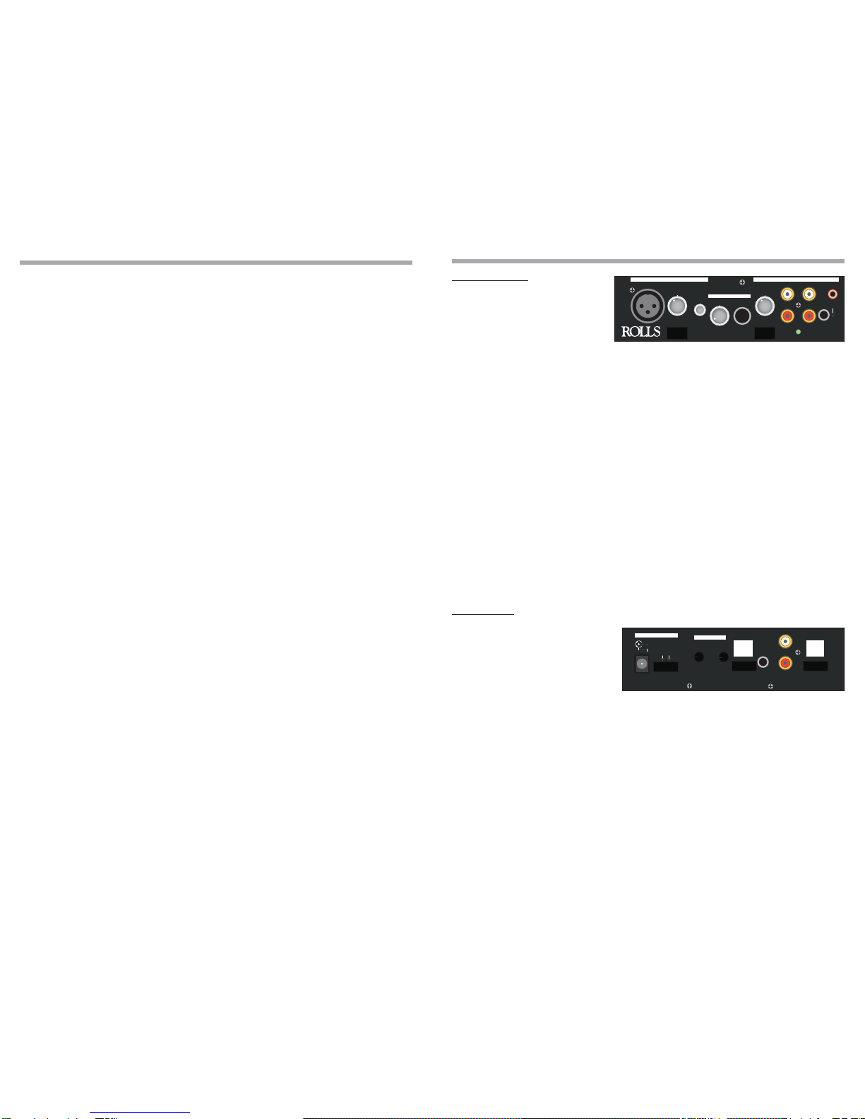
FRONT PANEL
MICROPHONE
INPUT: Balanced XLR
jack for connection to low imped-
ance dynamic or condenser micro-
phone.
LEVEL: Adjusts the amount of signal in the microphone preamp.
PHANTOM PWR: Header connector - connects the 12VDC phantom
power for the XLR Microphone Input.
BAL: Varies the relative amount of microphone signal sent to the Right
and Left Outputs.
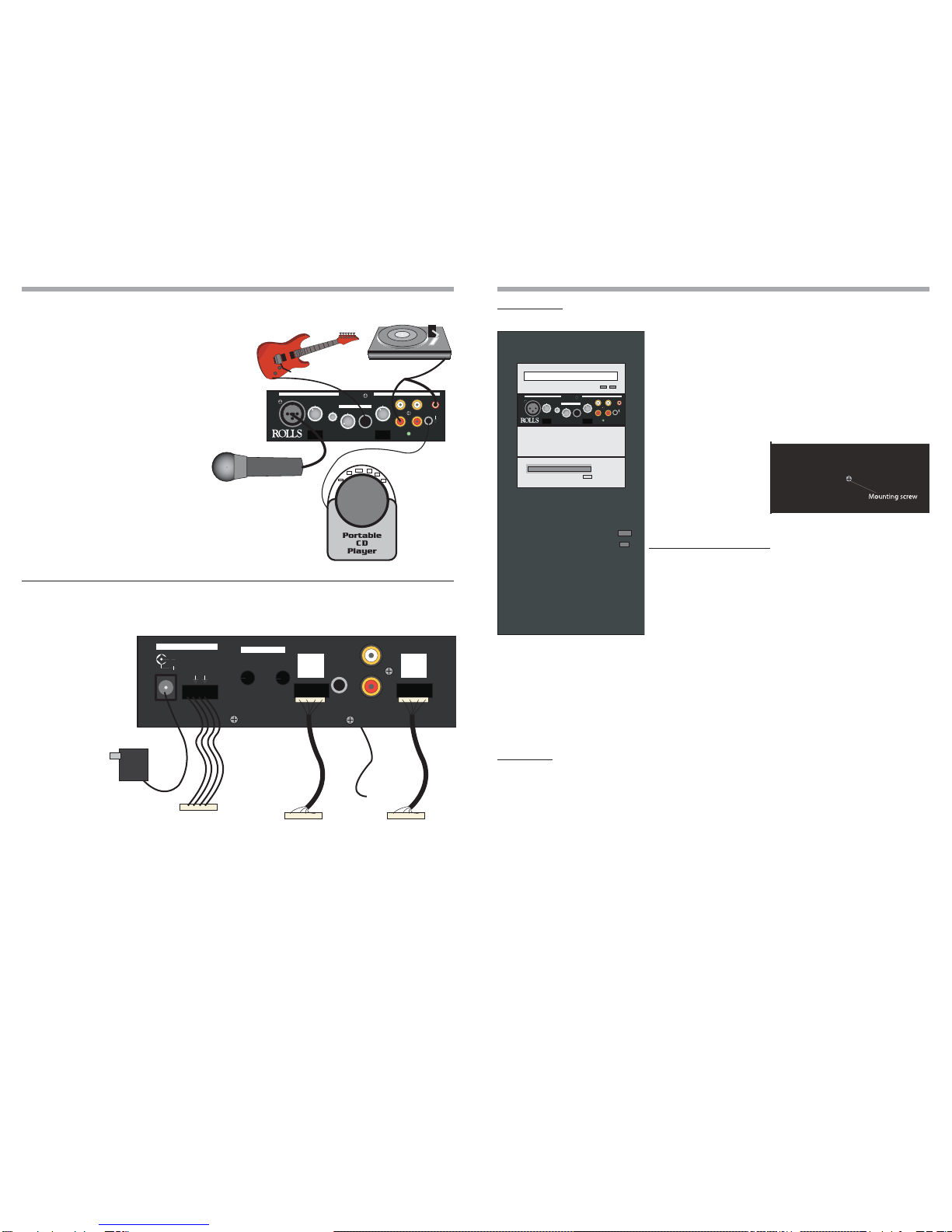
INSTRUMENT
LEVEL: Adjusts the amount of signal in the instrument circuitry.
INPUT: 1/4” unbalanced jack for connection to instruments such as
guitars, keyboards, etc.
PHONO/LINE
LEVEL: Adjusts the level of all device connected to the Phono or Line
Inputs.
INPUT (Phono): Two RCA jacks for connection specifically to the output of
a phono turntable.
INPUT (Line): Two RCA jacks for connection to line or consumer product
outputs such as a CD or cassette player.
STEREO INPUT: 1/8” (3.5mm) TRS stereo jack for connection to a stereo line
source such as a portable CD player or MP3 player.
GROUND: For connection to the grounding cable of a phono tuner.
DUCKING: Header connector - connects the Ducking function.
PWR: Indicates the GCi404 is properly connected to a power source.
REAR PANEL
POWER: 12VDC, 150mA. 2.1 x
5.5mm barrel jack and header port
- for connection to the Rolls PS27 AC
adapter, or to the computer’s 3 1/2
inch floppy drive power cable.
DUCKING
DEPTH: Adjusts the amount of LINE signal allowed to pass to the Outputs
when ducking is occurring.
RELEASE: The amount of time taken for the ducked LINE signal to return
to its normal level after the signal at the Mic Input stops.
CD INPUT Port: 4-pin header for connecting to a CD rom output port. A CD Rom audio
cable is required.
LINE OUTPUTS:
STEREO OUTPUT: (1/8” (3.5mm) jack)
LINE OUTPUT (RCA):
LINE OUTPUT (Header Port):
Each of these outputs contain the Right and Left output signals.
SPECIFICATIONS
MIC INPUT
Input Impedance: 10K Ohms bal, unbal.
Max Input Level:
+4 dBV XLR bal, +10 dBV unbal.
Max Gain: 60 dB/XLR, 54 dB 1/4”
EIN: -108 dB max.
THD: <.01%
Phantom Power: +12 Volts, 6 mA
INSTRUMENT INPUT
Input Impedance: 50k Ohms
Max Gain: 30dB
LINE INPUTS
Input Connectors: RCA, 1/8” TRS Stereo
Input Sensitivity: 30 dB gain @ 1kHz, 47k Ohms Input Z
Input Impedance: 50k Ohms
PHONO PREAMP
Input Impedance: 50k Ohms
Equalization: RIAA, +/- 2dB
Ref. Gain: +20 dB @ 1 kHz
LINE OUTPUTS
Output Impedance: 100 Ohms
Max Output Level: +12 dB
Frequency Response: + / - 1.5dB 15 Hz - 30 kHz
THD: .02% @ 1KHz
S/N Ratio: >80 dB unweighted
Output Connectors: RCA, 1/8” TRS - Stereo, 4-pin hdr.
Dimensions: 1.7”H x 5.9” W x 3.7” D
Weight: 1 lb.
Power: 12VDC (Rolls PS27 Incl.)
2
5
INPUT LEVEL
LEVEL
INPUT INPUT
LEVEL INPUT
PHAN PWR DUCKING
BAL
STEREO
INPUT
GCi 404 Audio - Computer
Interface
pwr
L R
ground
on off on off
MICROPHONE
INSTRUMENT
LINEPHONO
INPUT LEVEL
LEVEL
INPUT INPUT
LEVEL INPUT
PHAN PWR DUCKING
BAL
STEREO
INPUT
GCi 404 Audio - Computer
Interface
pwr
L R
ground
on off on off
MICROPHONE