manuals.online logo
Brands
  1. Home
  2. •
  3. Brands
  4. •
  5. Rolls
  6. •
  7. Recording Equipment
  8. •
  9. Rolls REQ315 User manual

Rolls REQ315 User manual

REQ315
GRAPHIC EQUALIZER
Constant Q
OWNERS MANUAL
LIMITED WARRANTY
This product is warranted to the original consumer purchaser to be free from
defects in materials and workmanship under normal installation, use and service for a
period of one (1) year from the date of purchase as shown on the purchaser’s receipt.
The obligation of Rolls Corporation under this warranty shall be limited to repair
or replacement (at our option), during the warranty period of any part which proves
defective in material or workmanship under normal installation, use and service, provided
the product is returned to Rolls Corporation, TRANSPORTATION CHARGES PRE-
PAID. Products returned to us or to an authorized Service Center must be accompanied by
a copy of the purchase receipt. In the absence of such purchase receipt, the warranty
period shall be one (1) year from the date of manufacture.
This warranty shall be invalid if the product is damaged as a result of deface-
ment, misuse, abuse, neglect, accident, destruction or alteration of the serial number,
improper electrical voltages or currents, repair, alteration or maintenance by any person or
party other than our own service facility or an authorized Service Center, or any use
violative of instructions furnished by us.
This one-year warranty is in lieu of all expressed warranties, obligations or
liabilities. ANY IMPLIED WARRANTIES, OBLIGATIONS, OR LIABILITIES,
INCLUDING BUT NOT LIMITED TO THE IMPLIED WARRANTIES OF MER-
CHANTABILITY AND FITNESS FOR A PARTICULAR PURPOSE, SHALL BE
LIMITED IN DURATION TO THE ONE YEAR DURATION OF THIS WRITTEN
LIMITED WARRANTY. Some states do not allow limitations on how long an implied
warranty lasts, so the above limitation may not apply to you.
IN NO EVENT SHALL WE BE LIABLE FOR ANY SPECIAL, INCIDENTAL
OR CONSEQUENTIAL DAMAGES FOR BREACH OF THIS OR ANY OTHER
WARRANTY, EXPRESSED OR IMPLIED, WHATSOEVER. Some states do not allow
the exclusion or limitation of special, incidental or consequential damages so the above
limitation or exclusion may not apply to you. This warranty gives you specific legal
rights, and you may also have other rights which vary from state to state.
ROLLS CORPORATION
SALT LAKE CITY, UTAH
3/02
INTRODUCTION
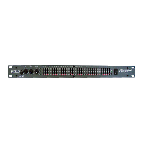
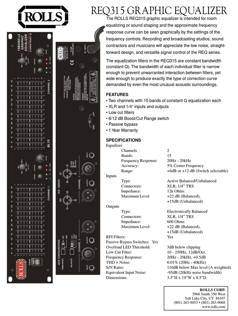
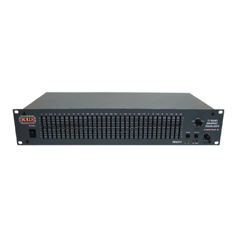
The ROLLS REQ315 graphic equalizer is intended for room equalizing or sound
shaping and the approximate frequency response curve can be seen graphically
by the settings of the frequency controls.Recording and broadcasting studios,
sound contractors and musicians will appreciate the low noise, straightforward
design, and versatile signal control of the REQ series.The REQ315 frequency
filters are “constant Q”meaning the width or shape of the filter curve does not
change as the frequency level is increased or decreased.This provides much
more accurate frequency adjustment.
INSPECTION
1.Unpack and inspect the REQ315 box and package.
If obvious physical damage is noticed, contact the carrier immediately to make a
damage claim.We suggest saving the shipping carton and packing materials for
safely transporting the unit in the future.
2.Please register online at www.rolls.com, or complete the Warranty Registration
Card and return it to the factory.
TABLE OF CONTENTS
1. Introduction
Inspection
Table of Contents
2. Description
Front Panel
Rear Panel
3. Operation, Installation
4. Example diagram
5. Schematic
6. Specifications
Back Cover: Warranty
SPECIFICATIONS
SPECIFICATIONS
Equalizer:
Bands 2x15 From 20Hz to 20kHz
Accuracy 3%Center Frequency
Range +/-6dB or +/-12dB (Switch Selectable)
Inputs:
Type Active Balanced/Unbalanced
Connectors 3-Pin XLR, 1/4 “ TRS
Impedance 12k Ohms
Maximum Level +22dB (Balanced) +15dB (Unbalanced)
Outputs: Type Relay Balanced
Connectors 3-Pin XLR, 1/4”TRS
Impedance 600 Ohms
Maximum Level +22dB (Balanced) +15dB (Unbalanced)
RFI Filters Yes
Passive Bypass Switches Yes
Overload LED Threshold 3dB (Below Clipping)
Low Cut Filter 10-250Hz, 12dB/Oct
Frequency response 20-20kHz +0.5dB
THD +Noise .01%(20hZ-40kHz)
Signal-to-Noise Ratio 110dB below Max. level (A weighting)
Equivalent Input Noise -95dB (20kHz Noise Bandwidth)
Dimensions: 3.5”H x 19”W x 8.5”D
1 6
SCHEMATIC
5 2
Front Panel Controls
1.Power Switch:
To turn the equalizer ON or OFF , press the upper or lower portion of this
button.
CAUTION: Always turn on your equalizer BEFORE your power amplifiers are
turned on , and always turn off your equalizer AFTER your power amplifiers
have been turned off.
2.Filter‘Level Controls:
Each of these sliders controls the output level of each of the 15 bandpass filters.
Center detent position is grounded for guaranteed flat response.
3.Filter Range Switch & Indicators:
The gain range of the filter sliders is switchable (as a group) from +/-6dB to +/-
12dB
For maximum boost/cut capability.At 6dB the green LED will illuminate and at
12dB the yellow LED will illuminate.
4.Bypass Switch & Indicator:
When the red LED is illuminated, this indicates that the unit or channel is in the
bypass mode.Signal is routed directly from the input to the output without
passing through any circuit (often referred to as “hard-wire bypass”).Use this
switch to compare equalized and unequalized material, or to bypass the EQ
section in the event of power loss or unit failure.
5.OverloadIndicator:
This red LED illuminates if any section of the equalizer is within 5dB of clipping.
Occasional blinking of this LED is acceptable, but if it remains on more than
intermittently you should turn down either the equalizer’s level controls or
reduce the output level of the preceding compon ent to avoid andible distortion.
6.Low-Cut Frequency Control:
To cut down unwanted signal, this control determines the roll-off frequencyof the
High-Pass Filter (HPF) in the instrument.The roll-off frequency cans de ad-
justed from 10Hz to 250Hz by turning this knob.Because of its high roll-off
slope, the HPF can be efficiently used to cut down the “HUM”noise from
preceding instruments, or to prevent the low-frequency resonance while the
speakers are installed in an enclosed acoustic environment.
7.Level Control:
This controls the level of signal coming into the instrument.Turn this control
down if the OVERLOAD LED illuminates steadily (meaning too strong on input
signal). Unity gain can be set by turning this knob to its center detent position.
EXAMPLE
43
8. Power Cord:
This cord is used to connect the AC power source to your equalizer.
CAUTION: DO NOT REMOVE THE CENTER GROUNDING PIN.
9. Fuse Holder:
This fuse holder contains an AC primary fuse.This fuse should be replaced
by the same type fuse when this is blown out.If they continuously blow, stop
replacing fuse and refer servicing to qualified personnel.
10. Input/OutputConnectors:
1/4 ”TRS
TheTRS (Tip Rinb Sleeve) connector is balanced and wired as tip=Lo (-) ,
Ring=Hi (+) , and the Sleeve = Ground.
CAUTION:Only one of these sockets can be chosen for audio connection at the
same time.
XLR
The XLR input connector is balanced and wired as Pin2=Lo (-) , Pin3=Hi (+) ,
Pin1=Ground
CAUTION: Only one of these sockets can be chosen for audio connection at
the same time.
Rear Panel Connectors & Controls
AUX 2
RETURN
0 10
AUX 1
RETURN/
TAPE IN LEVEL
0 10
HEADPHONE LEVEL
0 10
LEFT RIGHT
0
+20
+6
+14
-10
-15
-20
-30
-
+17
+8
0
-4
-13
HEADPHONE
OUTPUT
AUX 1
0 10
AUX 2
0 10
60
LOW
-15 +15
2.5 K
MID
-15 +15
12.5 k
HIGH
-15 +15
L R
BAL
11/12
0
+20
+6
+14
-10
-15
-20
-30
AUX 1
0 10
AUX 2
0 10
60
LOW
-15 +15
2.5 K
MID
-15 +15
12.5 k
HIGH
-15 +15
L R
BAL
9/10
0
+20
+6
+14
-10
-15
-20
-30
AUX 1
0 10
AUX 2
0 10
60
LOW
-15 +15
2.5 K
MID
-15 +15
12.5 k
HIGH
-15 +15
L R
BAL
7/8
0
+20
+6
+14
-10
-15
-20
-30
AUX 1
0 10 AUX1
0 10
AUX 2
0 10
60
LOW
-15 +15
2.5 K
MID
-15 +15
12.5 k
HIGH
-15 +15
L R
BAL
5/6
0
+20
+6
+14
-10
-15
-20
-30
AUX 1
0 10
AUX 2
0 10
60
LOW
-15 +15
2.5 K
MID
-15 +15
12.5 k
HIGH
-15 +15
L R
PAN
4
0
+20
+6
+14
-10
-15
-20
-30
AUX 2
0 10
60
LOW
-15 +15
2.5 K
MID
-15 +15
12.5 k
HIGH
-15 +15
L R
PAN
3
0
+20
+6
+14
-10
-15
-20
-30
AUX 1
0 10
AUX 2
0 10
60
LOW
-15 +15
2.5 K
MID
-15 +15
12.5 k
HIGH
-15 +15
L R
PAN
1
0
+20
+6
+14
-10
-15
-20
-30
AUX 1
0 10
AUX 2
0 10
60
LOW
-15 +15
2.5 K
MID
-15 +15
12.5 k
HIGH
-15 +15
L R
PAN
2
0
+20
+6
+14
-10
-15
-20
-30
-
-
-
-
-
-
-
-
TAPE
OUT TAPE
IN
R
L
TRIM
LINE
INSERT
MIC 1
INSERTINSERT
INSERT
LINELINELINE
TRIM
TRIMTRIMTRIMTRIM
TRIMTRIM
PHANTOM POWER LEFT
RIGHT
LEFT
RIGHT
LEFT
RIGHT
LEFT
RIGHT
RIGHT OUT AUX 2
RET.LEFT
LEFTOUT AUX 2
RET. RIGHT
AUX 1
RET. RIGHT
AUX1
RET.LEFT
AUX 1
OUT
AUX 2
OUT
MIC 2
MIC 3MIC 4MIC 5/6MIC 7/8MIC9/10MIC 11/12
+48V
OFF
+10
+60
+10
+60
+10
+60
+10
+60
+10
+60
+10
+60
+10
+60
+10
+60
P A
RA200
VOLUME2 VOLUME2
OWER MPLIFIER
Shown below is an example connection diagram for the REQ315.The main right
and left outputs of the mixer are connected to Channel 1 and 2 Inputs via high
impedance 1/4” unbalanced plugs.The equalizer is then connected to an ampli-
fier.
Note:This is only an example.For improved performance, use balanced XLR
connectors.

This manual suits for next models

1

Other Rolls Recording Equipment manuals

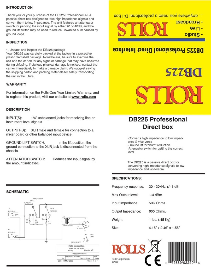
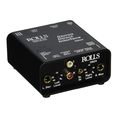
Rolls DB24 User manual

Rolls

Rolls DB24 User manual

Rolls ADB2 - 3/01 User manual

Rolls

Rolls ADB2 - 3/01 User manual

Rolls MP80 User manual

Rolls

Rolls MP80 User manual

Rolls SX95 Instruction Manual

Rolls

Rolls SX95 Instruction Manual

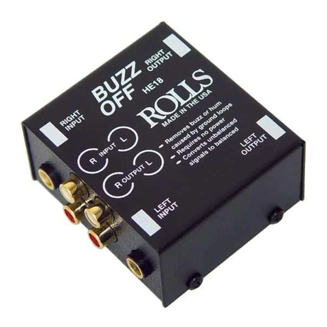
Rolls HE18 BUZZ OFF User manual

Rolls

Rolls HE18 BUZZ OFF User manual

Rolls WPM61 User manual

Rolls

Rolls WPM61 User manual

Rolls DB225 - 7-09 User manual

Rolls

Rolls DB225 - 7-09 User manual

Rolls HRD342 User manual

Rolls

Rolls HRD342 User manual

Rolls RDB109 User manual

Rolls

Rolls RDB109 User manual

Rolls GS76 User manual

Rolls

Rolls GS76 User manual

Rolls ADB2 User manual

Rolls

Rolls ADB2 User manual

Rolls req313 User manual

Rolls

Rolls req313 User manual

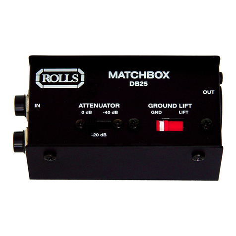
Rolls Direct Box DB 25b Reference manual

Rolls

Rolls Direct Box DB 25b Reference manual

Rolls REQ315 User manual

Rolls

Rolls REQ315 User manual

Rolls MP1288 User manual

Rolls

Rolls MP1288 User manual

Rolls MP80 User manual

Rolls

Rolls MP80 User manual

Rolls DB25 User manual

Rolls

Rolls DB25 User manual

Rolls SS412 User manual

Rolls

Rolls SS412 User manual

Rolls WPM61 User manual

Rolls

Rolls WPM61 User manual

Rolls HR73 - MANUAL 2 User manual

Rolls

Rolls HR73 - MANUAL 2 User manual

Rolls REQ131 User manual

Rolls

Rolls REQ131 User manual

Rolls DB225 User manual

Rolls

Rolls DB225 User manual

Rolls HR73 User manual

Rolls

Rolls HR73 User manual

Rolls ADi6 User manual

Rolls

Rolls ADi6 User manual

Popular Recording Equipment manuals by other brands

Eventide Instant Phaser user guide

Eventide

Eventide Instant Phaser user guide

Phonic MQ3300 user manual

Phonic

Phonic MQ3300 user manual

ALLEN & HEATH GL2400 Series user guide

ALLEN & HEATH

ALLEN & HEATH GL2400 Series user guide

Martin Audio M3 - SCHEMATICS user manual

Martin Audio

Martin Audio M3 - SCHEMATICS user manual

Viessmann VITOCONNECT OPTO2 Installation and operating instructions

Viessmann

Viessmann VITOCONNECT OPTO2 Installation and operating instructions

4ms Company Listen IO user manual

4ms Company

4ms Company Listen IO user manual

LuXout Shades LSPP-12V-29A-18S instructions

LuXout Shades

LuXout Shades LSPP-12V-29A-18S instructions

HMS INTESIS INMBSPAN001A000 user manual

HMS

HMS INTESIS INMBSPAN001A000 user manual

Ramsey Electronics SCA1 user manual

Ramsey Electronics

Ramsey Electronics SCA1 user manual

Panasonic AJLT85P - DVC PRO operating instructions

Panasonic

Panasonic AJLT85P - DVC PRO operating instructions

Niles ABA-1D Installation & operation guide

Niles

Niles ABA-1D Installation & operation guide

Tenor phono1 owner's manual

Tenor

Tenor phono1 owner's manual

Open Labs Openstudio OMX user guide

Open Labs

Open Labs Openstudio OMX user guide

ETS SMEA-1 instructions

ETS

ETS SMEA-1 instructions

urmet domus Agora 1372 Installation sheet

urmet domus

urmet domus Agora 1372 Installation sheet

RCS AUDIO-SYSTEMS PSS-224A operating instructions

RCS AUDIO-SYSTEMS

RCS AUDIO-SYSTEMS PSS-224A operating instructions

Cochlear Baha 4 user manual

Cochlear

Cochlear Baha 4 user manual

Yamaha DSP-100 Operation manual

Yamaha

Yamaha DSP-100 Operation manual

manuals.online logo
manuals.online logoBrands
  • About & Mission
  • Contact us
  • Privacy Policy
  • Terms and Conditions

Copyright 2025 Manuals.Online. All Rights Reserved.