WP61T
M
WIRELESSTRANSMITTER
DC
12345
7
8
96
(bottom) (back)
SPECIFICATIONS
TRANSMITTER
Frequency Response: 30 Hz - 15kHz
Frequency Stability: +/-10 ppm (under 25 degrees C)
Modulation: 10kHz +/- 2kHz (1kHz 50mV)
Transmitting Power: 10mW
Spurious Emission: 80dB below carrier
Distortion: <1%
Max AF Input Signal: 500mV
Power Source: 9V battery, or or external DC 12V
Current Consumption: 28mA +/-5mA
Dimension (LxWxH): 100x63x25 mm
RECEIVER
Sensitivity: 2.5 mV min (under squelch control)
Max.Power: 20mW min (at 16 Wspeaker load)
Distortion: 3% max (under 10mW output)
Frequency Stability: +/-0.01% ppm (under 25 degrees C)
Hum and Noise: - 50dB min
Power Source: 9V DC (alkaline recommended)
CurrentConsumption: DC 20mA max
Dimension: 60x25x100 mm
DESCRIPTION
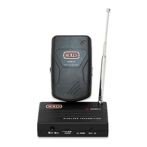
TRANSMITTER
1. Power Switch: Turns the WPM61t on and off. When pressed in, the
unit is ON.
2.Volume Control: Adjusts the level of signal coming into the WPM61t.
3. Low Battery LED indicator: Blinks when the power is turned on and
a battery is installed, will stay lit if voltage is below 5.5 to 6 Volts.
4. Power LED Indicator: When the transmitter is being powered via
battery, this light will blink momentarily during power-up. It will light
continuously when the transmitter is operated via an external adapter.
5. BATT/DC switch: External power source switch, this
switch MUST be moved to the BATT location
for the unit to operate on battery power.
Conversely, the switch MUST be moved to the
DC location when the unit is to be operated
via external 12 VDC power (Rolls PS27).
6. Audio Input (Labeled AF IN): 1/8" (3.5mm)
jack connect to a line level monitor source.
7. External 12 VDC input.Rolls model PS27.
8.Telescope Antenna: Extend fully for best
transmission/reception.
9. Battery Compartment: Location for 9V alkaline battery.
RECEIVER
1. Power Switch: Turns the WPM61r on and off.When moved toward the top of the
WPM61r, the unit is on. IMPORTANT!When theWPM61r is not in use, make sure
this Power Switch is turned OFF. Otherwise, the battery will continue to drain.
2. Power LED Indicator: Blinks when the Power Switch is first turned ON, will stay lit
when the battery drops below 5.5 to 6 volts and the receiver will no longer operate.
3. Audio earphone output (Labeled AF OUT): 1/8" (3.5mm) TRS stereo output jack.
4.Volume Control: Adjusts the output level of the WPM61r to the earphone jack.
5. Battery Compartment: Location for the 9 V alkaline battery. NOTE:The polarity for
installing the battery is shown below.The positive connection is toward the top of the
WPM61r, the larger negative connection is toward the bottom.
WPM6 1R
WIRELESS RECEIVER
1
2
3
4
5 (on back)
Battery installation
25

