Installation Instructions for Surface Wall Mount Electromagnetic Door
Holders Catalog Series EM 508 24120
P/N 3101128 ISSUE 1 © 2006
501-1012DE-1-01
Description
The EM 508 Series are surface wall mount door holders for use
with single doors. All are ULand cULListed and FM approved.
Installation
Install and wire in accordance with applicable codes, standards,
suchas NFPApublications70 (National ElectricalCode), 72 (Na-
tionalFireAlarm Code), and80 (Standardfor Fire Doors and Fire
Windows), and/or other regulations applicable to the country
and locality of installation and in accordance with authorities
having jurisdiction.
Table 1. Specifications
Cat.No. Volts Amps
EM 508 24120 24V AC 60 Hz 0.015
24V DC 0.015
120V AC 60 Hz 0.015
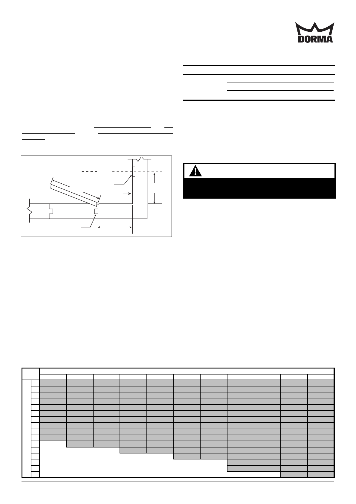
1. Using Figure 1 and Table 2, locate the intersection of
DimensionX and DimensionY. DimensionZ is shownat the
intersection in the gray area.
NOTE: If dimension X or Y is not shown on the chart,
extrapolate Dimension Z. (i.e., if X=7, and Y=30, Z
= (27-5/8 - ((27-5/8 - 27-1/4)/2)) => Z = 27-9/16" )
2. Mount the surface housing (supplied) vertically on the
horizontal center line and 5" from the top of the door with
two 1/4-20 x 1" screws (provided).
NOTE: The outlet box must be able to withstand a maximum
holding force of 50 pounds.
If X and Y intersect in the blank area in Table 2, DO NOT
install the outlet box. The contact plate and electromagnet
cannot be aligned with these dimensions.
Door
Door jamb
Wall line
Outlet box
center
line
X
Z
Y
Figure 1. Locating the Door Holder
Table 2. Dimension chart (in inches (mm))
Electromagnet Assembly Mounting
1. Refer to Figure 4. If not using surface metal raceway (not
supplied), secure the acrylic insulating sleeve (provided) to
the hole in the surface housing with the #8-32 x 3/16" screw
provided.
WARNING
To prevent electrical shock, ensure power is discon-
nected.
2. Pull field wiring through conduit into the surface housing. If
surface metal raceway (not supplied) is being used, the
required size is 1/2" wide x 11/32" high. The raceway will
seat 1/4" into the surface housing. Wiring should be run
through the acrylic insulating sleeve where applicable.
3. Establish earth-ground continuity in accordance with
applicable codes, standards and authorities having
jurisdiction.
4. Refer to Figure 2 and connect as instructed below:
a. 120V AC operation. Connect power field wiring to
terminalsmarked "120VAC"and "COM."
b. 24VAC/DCoperation. Connect power field wiring to
terminalsmarked "24VAC/DC"and "COM."
5. Mount the connected assembly onto the surface housing
and secure it with (2) #10-32 x 7/8" screws (supplied).
NOTE: The combined projection of the surface housing,
electromagnet assembly, and the armature assembly
is 4 1/16".
DORMA Architectural Hardware * Dorma Drive - Drawer AC, Reamstown, PA 17567
28 30 32 34 36 38 40 42 44 46 48
226 (660) 28 (711) 29 7/8 (759) 32 (813) 34 (864) 36 (914) 38 (965) 40 (1016) 42 (1067) 43 7/8 (1114) 45 5/8 (1159)
426 (660) 28 (711) 29 7/8 (759) 32 (813) 34 (864) 36 (914) 38 (965) 40 (1016) 42 (1067) 43 7/8 (1114) 45 5/8 (1159)
625 5/8 (651) 27 5/8 (702) 29 5/8 (752) 31 3/4 (806) 33 3/4 (857) 35 3/4 (908) 37 3/4 (959) 39 3/4 (1010) 41 3/4 (1060) 43 5/8 (1108) 45 3/8 (1153)
825 1/4 (641) 27 1/4 (692) 29 1/4 (743) 31 3/8 (797) 33 1/2 (851) 35 1/2 (902) 37 3/8 (949) 39 1/2 (1003) 41 1/2 (1054) 43 3/8 (1102) 45 1/4 (1149)
10 24 5/8 (625) 26 3/4 (679) 28 3/4 (730) 30 7/8 (784) 33 (838) 35 (889) 37 (940) 39 1/8 (994) 41 1/8 (1045) 43 (1092) 44 7/8 (1140)
12 23 3/4 (603) 25 7/8 (657) 28 (711) 30 1/8 (765) 32 1/4 (819) 34 3/8 (873) 36 3/8 (924) 38 1/2 (978) 40 5/8 (1032) 42 1/2 (1080) 44 3/8 (1127)
14 23 3/4 (603) 25 (635) 27 1/4 (692) 29 3/8 (746) 31 1/2 (800) 33 3/4 (857) 35 7/8 (911) 38 (965) 40 (1016) 42 (1067) 43 7/8 (1114)
16 21 3/4 (552) 24 (610) 26 1/4 (667) 28 1/2 (724) 30 3/4 (781) 33 (838) 35 1/8 (892) 37 1/4 (946) 39 3/8 (1000) 41 3/8 (1051) 43 3/8 (1102)
18 20 (508) 22 1/2 (572) 25 (635) 27 3/8 (695) 29 3/4 (756) 32 (813) 34 1/4 (870) 36 1/2 (927) 38 5/8 (981) 40 5/8 (1032) 42 1/2 (1080)
20 18 1/4 (463) 21 (533) 23 1/2 (597) 26 (660) 28 1/2 (724) 30 7/8 (784) 33 1/8 (841) 35 3/8 (899) 37 5/8 (956) 39 5/8 (1006) 41 5/8 (1057)
22 18 3/4 (476) 21 5/8 (549) 24 3/8 (619) 27 (686) 29 3/8 (746) 31 3/4 (806) 34 1/8 (867) 36 1/2 (927) 38 5/8 (981) 40 3/4 (1035)
24 22 1/2 (572) 25 1/2 (648) 28 1/8 (714) 30 5/8 (778) 33 1/8 (841) 35 5/8 (905) 37 7/8 (962) 40 (1016)
26 Do not install outlet box if 26 1/4 (667) 29 (737) 31 5/8 (803) 34 1/4 (870) 36 1/2 (927) 38 5/8 (981)
28 Dimensions X and Y intersect in this blank area. 29 3/4 (756) 32 1/2 (826) 34 7/8 (886) 37 1/8 (943)
30 The armature and electromagnet cannot be aligned. 27 3/4 (705) 30 5/8 (778) 33 (838) 35 3/8 (899)
32 31 3/8 (797) 33 7/8 (860)
X = Dimension of door jamb to wall
Y = Dimension of door width


