Rondish Nexus WCP-11C User manual

Rondish Company Limited
Nexus Call System
User Instructions
V2.0.4, December 2021

NEXUS CALL SYSTEM by Rondish
P2
Contents
1. PRODUCT OVERVIEW .............................................................................................................................. 4
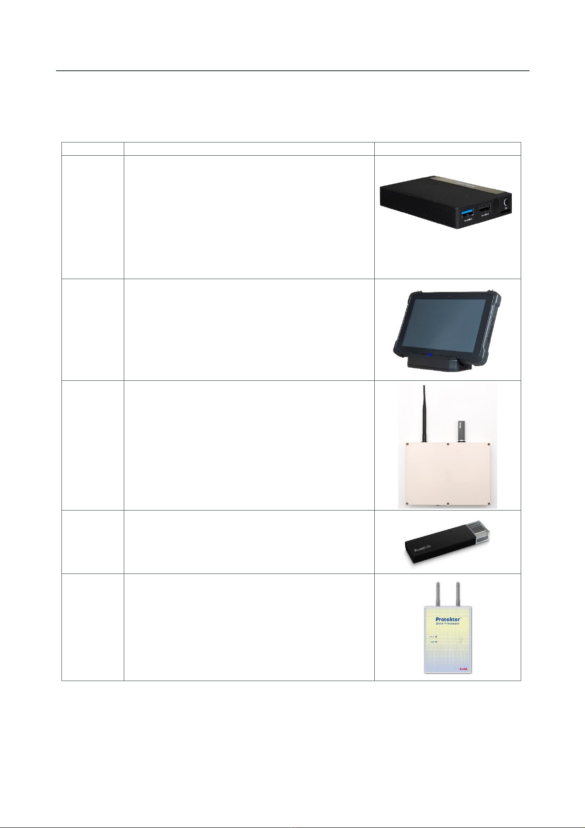
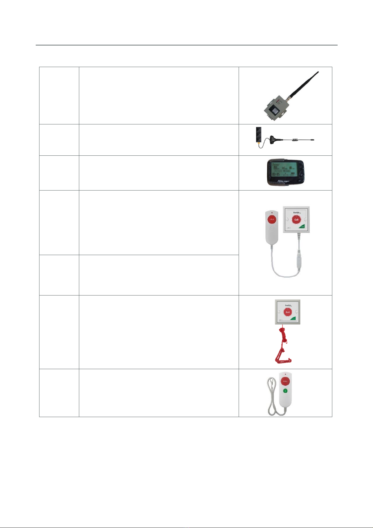
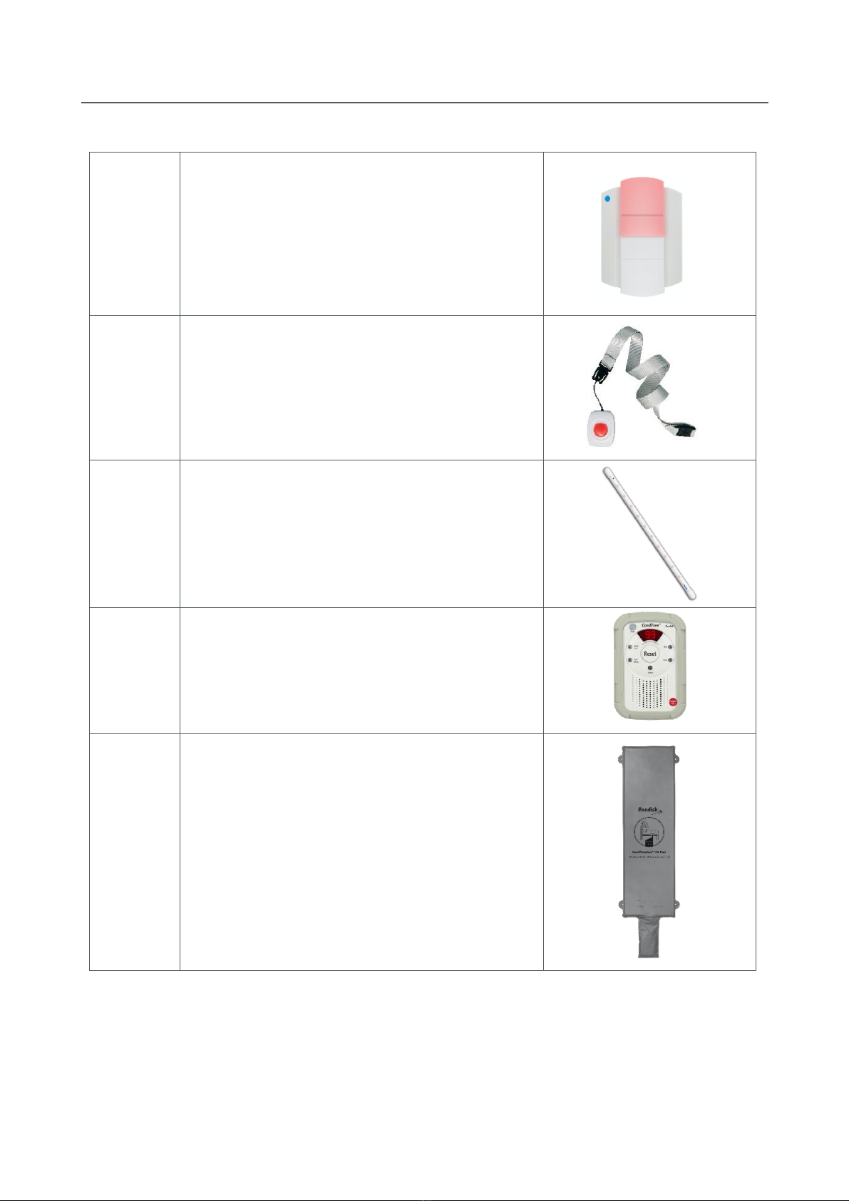
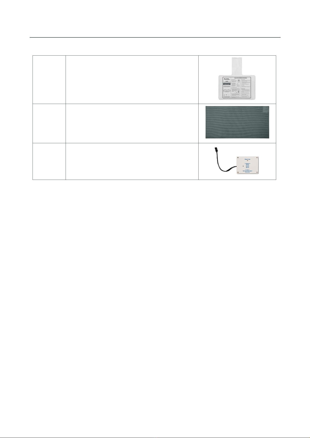
1.1 Compatible Equipment...................................................................................................................... 5
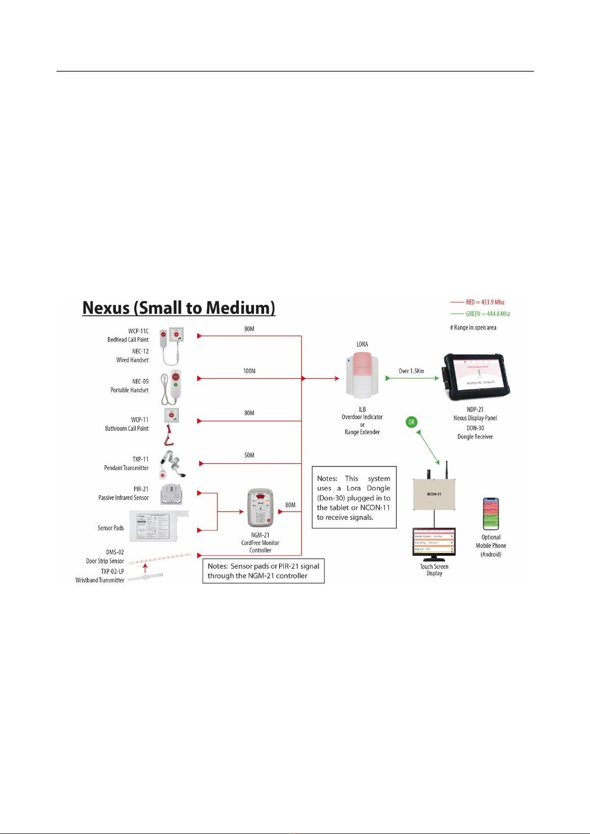
1.2 System Layout Options...................................................................................................................... 9
1.2.1 Receiver Dongle & Dome Lights ............................................................................................... 10
1.2.2 Master & Network Repeaters................................................................................................... 11
1.2.3 Messaging through Paging Transmitter ................................................................................... 12
1.2.4 Messaging through WiFi........................................................................................................... 13
1.2.5 Nexus Junction Box................................................................................................................... 14
1.3 General Operation........................................................................................................................... 15
1.3.1 Nexus Behavior Table ............................................................................................................... 15
1.3.2 Network Repeater Status ......................................................................................................... 15
1.3.3 Lost Device Detection............................................................................................................... 16
2. INSTALLING NEXUS ................................................................................................................................ 17
2.1 Master Station ................................................................................................................................. 18
2.1.1 Station Hardware...................................................................................................................... 18
2.1.2 Registering Nexus ..................................................................................................................... 19
2.2 Configuring a Repeater Network..................................................................................................... 21
2.2.1 Network ID................................................................................................................................ 22
2.2.2 Wireless Channel ...................................................................................................................... 22
2.2.3 Target Address.......................................................................................................................... 22
2.2.4 Data Rate .................................................................................................................................. 23
2.2.5 Repeater Address ..................................................................................................................... 23
2.2.6 Programming a Signal Hop ....................................................................................................... 24
2.3 Call Points ........................................................................................................................................ 25
2.4 Over-door Lights .............................................................................................................................. 26
2.5 Messaging........................................................................................................................................ 28
2.5.1 Transmitter/Receiver Setup ..................................................................................................... 31
2.5.2 Pager Setup............................................................................................................................... 32
2.5.3 Remote Display Setup............................................................................................................... 32
2.5.3 Call Escalation Setup................................................................................................................. 33
2.5.4 Smartphones............................................................................................................................. 37

NEXUS CALL SYSTEM by Rondish
P3
3. USING NEXUS......................................................................................................................................... 38
3.1 Home Screen ................................................................................................................................... 38
3.2 Alarm Screen.................................................................................................................................... 39
3.2.1 Display Details .......................................................................................................................... 39
3.2.2 Admin Reset.............................................................................................................................. 40
3.3 Device Management........................................................................................................................ 41
3.3.1 Add New Device........................................................................................................................ 41
3.3.2 Device Location......................................................................................................................... 42
3.3.3 Delete Device............................................................................................................................ 43
3.4 Event Log ......................................................................................................................................... 43
3.5 Settings ............................................................................................................................................ 45
3.5.1 Change Settings ........................................................................................................................ 45
3.5.2 Backup/Restore ........................................................................................................................ 46
3.5.3 Export Log................................................................................................................................. 46
3.5.4 Network Settings ...................................................................................................................... 47
3.5.5 Target IP Address...................................................................................................................... 47
3.5.6 Mobile Phone Provisioning....................................................................................................... 47
3.5.7 Messaging Settings ................................................................................................................... 47
4. MAINTENANCE ...................................................................................................................................... 48
4.1 Battery Life ...................................................................................................................................... 48
4.2 Nexus Updates................................................................................................................................. 48
5. TROUBLESHOOTING .............................................................................................................................. 49
Appendix: FCC & CE statements................................................................................................................ 50

NEXUS CALL SYSTEM by Rondish
P4
1. PRODUCT OVERVIEW
Nexus is a wireless call system designed for many applications including nurse and emergency call
applications, assisted living, elderly care homes, fast deploy systems, disabled bathroom alarms and other
applications. The system offers integrated emergency alarm call, wander prevention, bed alarms for fall
management, and mobile calling devices for residents to wear on their wrist or around the neck.
The system is supervised for lost connections, fault or battery low; and the main Nexus system includes a
software watchdog to restart the main program in the unlikely event of a system crash. A junction
controller box goes even further and includes a hardware watchdog as the ultimate safety feature.
Up to three calls can be displayed at a time, with higher priority calls automatically moved to the top of
the alarm display. Alarm priority levels are Emergency, Bath/Bed/Door, and standard Call. If more than
three calls happen to be active at the same time, the three highest priority events will be shown, and
lower priority/newer calls will display as the higher priority/older events are reset or can be shown by
scrolling down the screen. All events are logged with a record of event location, call type, time of trigger
and duration.
Optional Over-door lights show Call, Bath or Emergency status. Each light has an internal buzzer with
adjustable volume, and can repeat the signal to greatly extend range and improve the reliability of
wireless coverage. These can battery power, DC powered or both.
Several messaging options are available, including remote monitor displays large or small, mobile phones,
pagers and LED displays. These can work through a paging transmitter, the existing WiFi network, or a
dedicated mesh WiFi installed for this purpose.

NEXUS CALL SYSTEM by Rondish
P5
1.1 Compatible Equipment
Model
Description
Image
TVB-21
Nexus Control Box
Operate Nexus as a desktop computer or touch
screen
Bluetooth compatibility for mouse and keyboard
Connect either DON-30 Receiver Dongle or ZP-
01(M) Master Controller to establish a wireless
network for your facility
Connect with GP2009TR to enable remote corridor
displays
Ethernet port allows network of multiple stations
NDP-21
Nexus Rugged Tablet
Operate Nexus as a desktop touch screen
Connect either DON-30 or ZP-01(M) to establish a
wireless network for your facility
Docking station includes three USB ports for
paging transmitter or
Ethernet port allows networking of multiple
stations
NCON-11
Nexus Junction Box
Includes TVB-21
Includes GP2009TR
Connects with DON-30 or ZP-01(M) to establish a
wireless network for your facility
Surge protection and watchdog functionality to
restart Nexus if system becomes unresponsive
Connects to touch screen monitor or other device
through WiFi connection
DON-30
Receiver Dongle (LoRa)
Links with ILB-21 Over-door lights for smaller areas
ZP-01(M)
ZP-01(S)
Master Controller & Network Repeaters
ZP-01(M) Master connects with tablet or
Controller Box to operate the system
ZP-01(S) Expands wireless coverage of your system
using system (up to 2km open space)
Allows use of bed monitoring, door monitoring,
and patient pendants

NEXUS CALL SYSTEM by Rondish
P6
GP2009TR
Paging Transceiver
Signal to remote displays or data pagers
Repeats signal to extend range
GP2016TR
Paging Receiver
Receives signal from GP2009TR for use on Remote
Displays
GP2009N
Data pager
Displays alarm details set on Nexus
WCP-11C
Bedhead call/reset point (shown)
Call and reset buttons
Double press sends Emergency call
RJ10 input for NEC-12 handset (shown)
Handset remove alert
Includes mounting screws
Replaceable CR2477 lithium batteries
Low battery indication
NEC-12
Patient handset
Call button for patient access from the bed
RJ10 plug connects with WCP-11C
USB break connection
Includes wall-mount bracket and screws
WCP-11
Waterproof call/reset point
Call and reset buttons
Pull cord with dual triangles
Includes mounting screws
Replaceable CR2477 lithium batteries
Low battery indication
Rated IP65
NEC-05
Wireless patient handset
Call and reset buttons
Includes wall-mount bracket and screws
Uses 2 x AAA alkaline batteries
Low battery indication
NEC-12
WCP-11C

NEXUS CALL SYSTEM by Rondish
P7
ILB-21
Over-door light
Dual-color LED light –shows RED for normal call
devices or WHITE for bath units
Buzzer with adjustable volume
Call forward function to extend range
Includes wall-mount bracket and screws
Uses 6 x C-type alkaline batteries
Low battery indication
TXP-11
Patient lanyard with man-down alert
Mobile call button for active residents
Anti-ligature point
Man-down alert in case of falls
Replaceable CR2450 lithium battery
Low battery indication
Rated IP65
DMS-02
DoorWatcher Sensor
Triggers audible and visual alert when an at-risk
patient approaches a protected doorway
Configurable with door lock to restrict access
Allows caregivers to escort patients through a
protected door without alarming
NGM-21
CordFree Monitor
Room controller for integrated falls management
system
Pause & Reset alarms
Works with bed/chair/floor sensormats
Uses 3 x AA alkaline batteries
Low battery indication
WMBP-20
Cordless under-mattress sensorpad
Triggers alarm from patient bed exit
Invisible to residents for improved comfort
More hygienic than standard sensorpads that
come into contact with the skin
Paired with NGM-21 monitor
Durable and long-lasting
Low battery indication (from TM-11 transmitter
module)

NEXUS CALL SYSTEM by Rondish
P8
CCP-01
Cordless chair sensorpad
Triggers alarm from patient chair exit
Paired with NGM-21 monitor
Durable and long-lasting
Low battery indication (from TM-11 transmitter
module)
CMAT-02
Cordless floor sensormat
Triggers when stepped upon
Paired with NGM-21 monitor
Durable and long-lasting
Low battery indication (from TM-11 transmitter
module)
TM-11(V3)
Transmitter module
Insert into Cordless sensorpad or floor mat to
connect with NGM-21 Cordfree monitor
15 months battery life

NEXUS CALL SYSTEM by Rondish
P9
1.2System Layout Options
Nexus uses a proprietary wireless format to direct signals from call points and sensory devices to a nurse
station, where calls are displayed on the main Nexus panel. Once received, this panel can direct messaging
to staff using either a paging transmitter or a local WiFi network, where messages can be displayed on
Remote displays, pagers or Android phones. Note: The local WiFi can be a network already installed in
the building or a dedicated mesh separate network installed.
Several receiving options are available to cover buildings of various sizes. Signals are brought into the
Android device using a Receiver Dongle (DON-30) for smaller areas, or Master Controller and Network
Repeaters (ZP-01(S)), which relay the call points and sensory devices status. When using Network
Repeaters, signals can be “hopped” from one repeater to another to further extend the wireless coverage.
The following layout diagrams give an overview to the options available depending on the complexity and
size of the building and type of equipment required.

NEXUS CALL SYSTEM by Rondish
P10
1.2.1 Receiver Dongle & Over-Door Lights
Rondish Over-door lights (ILB-21) receive local signals from a variety of calling units, and can either be
configured as lights/sounder by reading into memory the calling unit, or set up to just extend the system
coverage without any local alarm. The ILB-21 uses bi-directional communication with a Receiver Dongle
(DON-30) plugged into the Rugged Tablet (NDP-21), Nexus Control Box (TVB-21), or Nexus Junction Box
(NCON-11).
When used as a range extender the ILB-21 transmitter uses LoRa on a separate 400MHz channel to the
calling device. When connecting the ILB-21 you should check the range using the programing magnetic
key as this reduces the signal by 3bB to ensure the normal connection is secure (see the ILB-21 installation
instructions). The open-air ranges of the devices are shown on the diagram below.
The ILB-21 can be battery operated with a standby life of 18 months –ideal for a fast deploy or bathroom
alarms –or powered from a 12V supply with batteries used as backup.

NEXUS CALL SYSTEM by Rondish
P11
1.2.2 Master & Network Repeaters
Medium to Large systems can be set up using a Master (ZP-01(M)) and Network Repeater (ZP-01(S))
configuration. The advantage of this system over LoRa is higher speed and larger RF coverage. This allows
for a network to be put together inside the building and the system networked using hops if required to
extend the range.
Example: Multi-floor building
Up to 3 hops can be used on the
system, and using the RSSI readings
viewable through the Event log on
Nexus this can be optimized for the
best layout.
There may be a bit of trial and error
to achieve the best RSSI levels by
changing the target address and
seeing if the RSSI level is higher or
lower.
You will be able to cover large areas
and multi-floor buildings using this
method to configure the system.

NEXUS CALL SYSTEM by Rondish
P12
1.2.3 Messaging through Paging Transmitter
The Nexus display panel can be programmed to send signals to the pagers/displays using POCSAG codes
(Refer to GP2009TR UI for details of configuring transmitters and setting capcodes). The paging
transmitter can be connected to the USB port on the NDP-21 docking station (See Section 2.1.1), allowing
messaging to pagers or LED display panels. This has a range up to several Km/miles and can send a signal
to a pager or a wireless LED display as shown.
Paging to remote display and pager receiver
Remote display with Mobile phone using the cloud

NEXUS CALL SYSTEM by Rondish
P13
This setup is applicable where the local WiFi is unavailable but the user prefers a mobile phone and
computer based remote displays. In this case the remote displays can be Tablets or Android based
displays with a paging receiving dongle. The mobile phone app (Samsung phone recommended) can be
added providing the Nexus console is connected to the internet and uses the cloud and local GSM
network.
1.2.4 Messaging through WiFi
Presently under development is a WiFi based option of the system for both the remote displays and the
mobile phone using the internal LAN or mesh network. The WiFi network can be either use a system that
is already installed or can be easy installed using a Mesh WiFi system.

NEXUS CALL SYSTEM by Rondish
P14
1.2.5 Nexus Junction Box
This is based on the mini android computer which can be connected to various monitors of different sizes.
The Nexus Junction Box (NCON-11) has been designed as a control box so that you can simply plug into
the box the items that you require including DON-30, ZP-01(M), Paging transmitter, touch screen monitor.
In addition, Rondish will soon have a local point to point WiFi link to an NDP-21, which will allow the NDP-
21 to be placed freely within a room and the NCON-11 placed outside in the corridor, thereby increasing
the coverage and making the system very flexible.
The NCON-11 includes various features such as power handling (surge suppression, fuses, regulators) with
outputs for the various items, AC lost and battery low detection, and includes a hardware watchdog to
reset the system in the unlikely event of a system crash. For main Nexus monitor we recommend a
touchscreen for ease of use, although a Bluetooth mouse or keyboard can also be used.

NEXUS CALL SYSTEM by Rondish
P15
1.3 General Operation
Nexus follows general accepted principles of a nurse call system as described in the UL and HTM-08
standards. Patient calls should be reset at location by the nurse or caregiver as soon as can reasonably
be achieved.
1.3.1 Nexus Behavior Table
The table below summarizes how Nexus interprets and displays signals from various devices:
Device
Alarm
Trigger
Alarm
Type
Nexus Display
Over-door
Light
Cancel Alarm by…
WCP-11C
Single
press
Call
Yellow, 10s
beep intervals
Red
Reset on WCP-11C
WCP-11C
Double
press
Emergency
Red, Rapid
beeping
Alternating
Red/White
Reset on WCP-11C
NEC-12
Press
button
Call
Yellow, 10s
beep intervals
Red
Reset on WCP-11C
WCP-11
Press
button
Bath
Amber, 4s beep
intervals
White
Reset on WCP-11
WCP-11
Pull cord
Bath
Amber, 4s beep
intervals
White
Reset on WCP-11
TXP-11
Press
button
Call
Yellow, 10s
beep intervals
Red
Magnetic fob on TXP-11
TXP-11
Patient fall
Emergency
Red, Rapid
beeping
Alternating
Red/White
Magnetic fob on TXP-11
NEC-05
Press
button
Call
Yellow, 10s
beep intervals
Red
“C” button on NEC-05
DMS-02
Door exit
Door
Amber, 4s beep
intervals
White
Magnetic fob on DMS-02
or press TXR-02 button
NGM-21
Bed/Chair
exit
Bed exit/
Chair exit
Amber, 4s beep
intervals
White
Reset on NGM-21 or
Pad return
1.3.2 Network Repeater Status
The ZP-01(S) is a critical part of Nexus operation, as it is the link between the wireless calling devices and
the Master controller, then to Nexus. If you think this is not working properly, the LED can give an
indication of the current status.

NEXUS CALL SYSTEM by Rondish
P16
Dongle Indications
Green LED steady, Red LED flashing –Repeater cannot connect with the master
Green flashing LED –Repeater successfully connected with the master
Red flashing LED –Repeater receiving data
An error message will display if the Receiver Dongle or Master Controller ZP-01(M) is removed or loses
connection while Nexus is active. Your system cannot function without this receiver connected, so Nexus
will prompt you to resolve this before any further action can be taken.
1.3.3 Lost Device Detection
Nexus will display any faults that are detected within the local network. Warnings display according to
the schedule below:
Call devices –24hrs
Signal repeaters –10mins

NEXUS CALL SYSTEM by Rondish
P17
2. INSTALLING NEXUS
Nexus is designed for a straightforward installation process that minimizes your time spent on site.
Following these steps will have your system up and running in just a few hours:
1. Switch on the tablet/TV Box and connect the receiver dongle DON-30 or Master Controller ZP-
01(M) –the application will automatically open to a splash screen displaying the version of Nexus
installed on this device
2. Change the PIN and enter name of organization (optional) in the Settings menu. If a receiver
dongle DON-30 is used, skip to Step 5. If repeaters are used you must configure the Network ID
and Channel.
3. Program ZP-01(S) repeaters to use the same Network and Channel selected at Master Controller
ZP-01(M). When all Repeaters in the network are initialized by the Master, power up or
connection, check the RSSI values shown in the Event Log. Rondish recommends programming a
signal hop if recorded RSSI values are below 100
4. Pair call points and sensors with Nexus and define how each should display during a call –refer to
Section 3.3 for details of adding and renaming devices.
5. Pair call points and sensors with over-door lights (optional)
6. Mount over-door lights (if used), call buttons and brackets for patient handsets
7. Test all of the call points three times (call & reset) to ensure that signals are reliably received by
the Nexus

NEXUS CALL SYSTEM by Rondish
P18
2.1 Master Station
Start your installation by powering up the device you will use for the Master Station. There are two
current hardware options:
2.1.1 Station Hardware
Nexus can operate on a Rugged Tablet (NDP-21) for an easily configurable desktop solution, or on a
versatile Control Box (TVB-21) that allows a monitor or any size to be connected. A System Controller
(NCON-11) includes a Control Box, Paging Transmitter, USB hub and failsafe circuitry in one housing, and
will allow the user to interface with Nexus using a touch screen or wireless keyboard & mouse.
Nexus Rugged Tablet (NDP-21)
The Rugged Tablet comes with a docking station that allows convenient placements on a nurse desk. The
back of the docking station includes three USB connections, allowing a DON-30 or ZP-01(M) to connect a
network, and a GP2009TR paging transmitter to signal paging signals.
Connect the power adapter provided
Insert ZP-01(M) to launch Nexus
The docking station has three USB ports for a
receiver, paging transmitter and data backup.
The LAN allows connecting to a database.

NEXUS CALL SYSTEM by Rondish
P19
Nexus Control Box (TVB-21)
The Control Box can also be used for remote displays for corridors, and an ethernet port allows multiple
stations to be networked with a central database.
Connect the power adapter provided
Connect with HD monitor using HDMI cable
Connect Bluetooth keyboard and mouse in Setting -> Connected Devices -> Pair new devices, then
follow the instruction
Insert DON-30 or ZP-01(M) to launch Nexus
Disable AC Lost/Low battery Warning is turned OFF in the Settings menu
Nexus Control Boxes can also be configured with remote displays mounted on a wall or corridor. For
details, see Section 2.5.3.
Power input
HDMI –Computer
monitor
Ethernet –to LAN
for database
Audio out –external
speaker
Power button
USB 2.0 –Dongle or ZP-
01(M)
USB 3.0 –GP2009TR
paging transmitter

NEXUS CALL SYSTEM by Rondish
P20
Select the country where the license was
issued.
Enter the email address the license of the
person who contacted Rondish to
purchase the equipment.
Enter the password
Enter the Product key
2.1.2 Registering Nexus
Nexus will automatically launch when you connect a receiver dongle DON-30 or ZP-01(M) into the USB
port of an Android device with the app installed. If you have purchased a device from Rondish it will come
with Nexus pre-installed with a registered software license for your organization. If you are loading Nexus
onto a device not purchased from Rondish you will be prompted to enter a registration key the first time
Nexus is launched.
The email address and password used for the software registration will allow you to update Nexus as new
features are implemented. See Section 4.2 for details.
2.1.3 Activating/Deactivating Kiosk Mode
Enabling this feature will ensure that a user cannot exit Nexus and use other applications once Nexus has been
launched.
To exit kiosk mode, press “Device Management” or “Settings” and key in passkey 930329 to temporarily
disable the function.
This manual suits for next models
19
Table of contents
Other Rondish Medical Equipment manuals
Popular Medical Equipment manuals by other brands

Gainsborough
Gainsborough KENT 1800 Series 2 Information manual

SKF
SKF TKES 10 Series Instructions for use

AMT
AMT Bridle Standard Directions, Indications, & Contraindications For Use

medi
medi protect.Ankle air foam Instructions for use

Blatchford
Blatchford Navigator Instructions for use

Roscoe Medical
Roscoe Medical GN3278 Quick reference guide