– 6 –
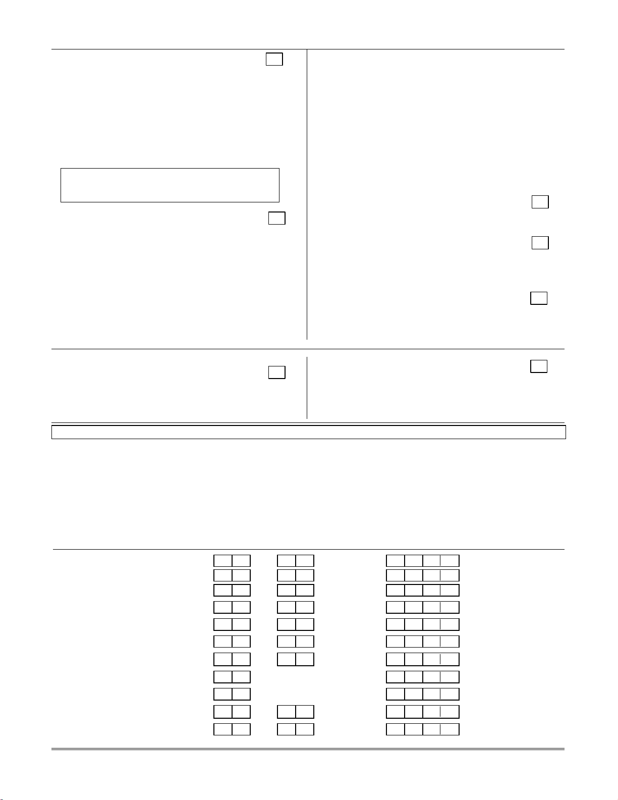
✱46 REPORT FORMAT [7] †
0 = 3+1, 4+1 ADEMCO L/S STANDARD
1= 3+1, 4+1 RADIONICS STANDARD
2= 4+2 ADEMCO L/S STANDARD
3 = 4+2 RADIONICS STANDARD
6
or undefined = 4+2 ADEMCO EXPRESS
7
= ADEMCO CONTACT ID®REPORTING
8
= 3+1, 4+1 ADEMCO L/S EXPANDED
9
= 3+1, 4+1 RADIONICS EXPANDED
For an explanation of these formats, refer to the
SYSTEM COMMUNICATION section of the
Installation Instructions.
✱47 SPLIT/DUAL REPORTING [0]
0 = Disable (Backup report only)
TO PRIMARY PHONE NO. TO SECONDARY PHONE NO.
1 = Alarms, Restore, Cancel Other Reports
2 = All except Open/Close, Test Open/Close, Test
3 = Alarms, Restore, Cancel All Reports
4 = All except Open/Close, Test All Reports
5=All (Dual Reporting) All Reports
TO PRIMARY PHONE NO. TO PAGING NO.* (Secondary)
6=AllexceptOpen/Close **Alarms,Open/Close, Troubles
7=Allreports **Alarms,Troubles
8=Allreports **Alarms,Open/Close, Troubles
9 = All except Open/Close **Alarms, Open/Close for
users 5-25***, Troubles
*Can only be used if Primary reporting is ADEMCO Contact
ID®.
**
A 10-digit code is sent to the pager consisting of a 4-digit
Subscriber No., a 3-digit Event code, and a 3-digit User (or
Zone No.). See VISTA-10SE Installation Instructions for an
explanation of the paging format.
*** Refer to field ✱47 in the DATA FIELD DESCRIPTIONS
section of the Installation Instructions.
✱48 15 SEC DIALER DELAY (BURG) [0] †
0 = no delay; 1 = 15 sec delay
UL installations: 0 must be selected .
✱49 PERIODIC TEST MESSAGE [0] †
0 = none; 1 = 24 hours; 2 = weekly; 3 = monthly
(Enter Test Code in field ✱64.)
UL installations: 1 (24 hours) must be selected.
✱50 SESCOA/RADIONICS SELECT [0] †
0 = Radionics (0 – 9, B – F reporting);
1 = SESCOA (0 – 9 only reporting)
Select 0 for all other formats.
✱51 CONFIRMATION OF ARMING DING [0] †
0 = disables ding;
1 = enables 1/2 sec ding
2 =
enables 1/2 sec ding from RF arming
✱52 ZONE 3 RESPONSE TO OPEN [0] †
0 = 400mS nominal; 1 = 10mS nominal
†Entry of a number other than one specified will give unpredictable results.
✱
✱✱
✱56 / ✱
✱✱
✱58 ZONE ASSIGNMENT/ALARM REPORT CODES
These fields are interactive modes. Fill in the required data on the worksheet below (and on next page) and follow
the programming procedure in the installation manual. Zone Types are shown on the next page of this manual.
NOTE: All numbers in brackets [ ] are default settings.
ZONES ON CONTROL: See explanation of headings on next page →
→→
→
ZONE ZONE ALARM RPT CODE INPUT RF
ZONE NO. TYPE (Hex) TYPE INPUT
DESCRIPTION (Zn) (ZT) (RC) (In) (RT)
Wired Zone 1 0 1 [01] [01] [00] HW —
Wired Zone 2 0 2[04] [01] [00] HW —
Wired Zone 3 0 3[03] [01] [00] HW —
Wired Zone 4 04[03] [01] [00] HW —
Wired Zone 5 05[09] [01] [00] HW —
Wired Zone 6 06[07] [01] [00] HW —
Keypad Panic (✱& #, or B) 07[06] [01] [00] ——
Keypad Duress 08——[00] [00] ——
Tamper 0 9 05[01] [00] — —
Keypad Panic (1 & ✱, or A) 95[00] [01] [00] — —
Keypad Panic (3 & #, or C) 96[00] [01] [00] — —