Quadnet Installation Instructions
8
Topology & Cabling
All system wiring should be installed to comply with BS 5839: Pt 1: 2002: Amendment 2: 2008 and BS 7671
(wiring regulations) and any other standards relevant to the area or type of installation. A cable complying
with the BS 5839: Pt 1: 2002 Category 1 (cables required to operate for prolonged periods during fire
conditions) is required. This must be a 2-core 1.5mm
2
screened fire resistant cable (ie. MICC, FP200,
Firetuff, Firecell, Lifeline or equivalent). Ventcroft No-Burn multicore cable was utilised during the LPCB
approval testing.
The addressable circuit must be installed as a loop with a maximum loop length of up to 2 km. Addressable
spur circuits (covering up to a maximum of one detection-zone only per spur circuit and up to a maximum
of 100m in length) may be connected at each Multipoint detector, as long as the combined addressable
circuit length does not exceed 2 km.
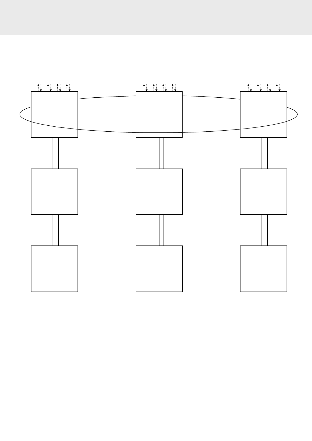
The network cable should generally be installed as a single ring, but due to the provision of four network
ports at each panel, sub rings may be installed if required. Whilst radial circuits may be implemented
successfully, they are generally not recommended as they are less fault tolerant and lack system integrity.
Network connections must be installed with a maximum length of 500m between network ports.
The Power Supply Unit requires both a data connection and dual power connections. Thus, one x 2 core
1.5 mm
2
screened fire resistant cable must be installed between the PSU and the Control Panel for data
connections, and 2 x 1.5 mm
2
screened fire resistant cable must be installed between the PSU and the
Control Panel for 24v DC power connections if each cable is no longer than 20m (use 2.5 mm
2
for 24V DC
power cables up to a maximum of 30m).
In order to protect against possible data corruption it is important ensure the following points are adhered
to:
1. The addressable circuit (loop) cable screen must be connected to earth/ground at the
control panel at each end using the terminals provided.
2. The addressable circuit (loop) cable screen must not be connected to earth/ground at any point
other than the control panel, ie, do not connect the screen to a device back box.
3. The cable screen continuity must be maintained at every point of the loop, using the
terminals provided or a suitable connection block.
4. Do not use a 4-core cable as a loop feed & return due to the possibility of data corruption. It is
essential that two 2-core cables are used if this is required.
5. The network connection cable screens must be connected to earth/ground at the control
panel at one end only using the terminals provided.
Refer to the following wiring schematics for further details.