Room essentials 430238 User manual

>> assembly instructions
room essentials
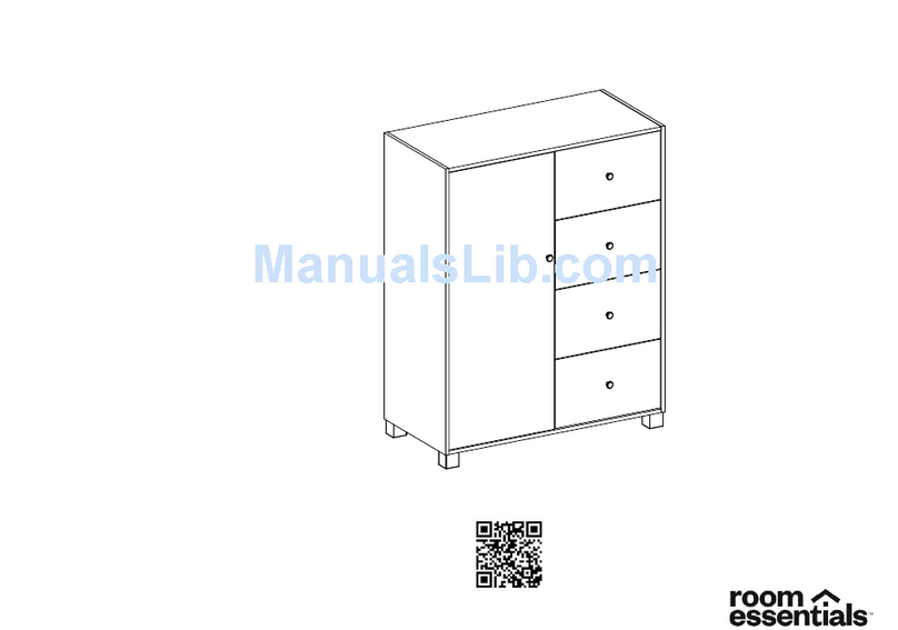
4-drawer chest
style # 430238 (white)
dpci # 249 - 05 - 0003

2
Congratulations on your latest Target purchase.
Now what? Don’t start sweating over this box of parts. This will be easy. We did the hard work for you.
All you need to do is follow our simple instructions and you’ll be on your way to transforming your room in no time.
Good luck—though we’re confident you won’t need it.
tools needed
before you begin
1. Check for damaged or missing parts. Visit www.sauder.com/services to order missing supplies.
2. Use the carton as a working surface to prevent product damage during assembly.
3. Gather all tools prior to assembly.
tip shown
actual size
430238

3
a note from the manufacturer:
register your product online.
www.sauder.com
For immediate service, our website is available 24 hours a day,
7 days a week to order replacement parts, access assembly tips,
register your product, and view Sauder products.
Monday – Friday 9am – 5:30pm ET
United States and Canada (except holidays)
Consumer Services 1-800-523-3987
Most replacement parts ship from our facility in one or two business days.
Please contact Sauder customer service before returning your product to
the store. Most questions, concerns, or parts needs can be addressed
by Sauder customer service assistance at www.sauder.com/services.
NOTE: This instruction booklet contains important safety information.
Please read and keep for future reference.
Record the date you purchased this unit and save the booklet for future
reference. If you ever need to contact Sauder about this unit, refer to
the lot # and the style # when calling our toll-free number.
For more information about our furniture, company, or to order
replacement parts, please visit our web site.
Lot #: 560425
Date Purchased:______________ 02 / 04 / 21
430238
table of contents
introduction 2
part list 4
hardware 5
assembly 6-21
warranty 22
important safety information 23

4
part list
While not all parts are labeled, some of the parts will have a label or an inked letter on the edge to help distinguish similar parts from each other.
Use this part list to help identify similar parts.
ITEM DESCRIPTION QUANTITY
A right end 1
B left end 1
C top 1
D brace 3
D44 right drawer side 4
D45 left drawer side 4 (1 with label)
D182 drawer back 4
D988 drawer bottom 4
E bottom 1
F side skirt 2
G skirt 1
H upper drawer front 1
J lower drawer front 3
K lower back 1
L upper back 1
M67 drawer brace 4
(Hidden part using
recycled material.
Color may vary.)
430238
A
B
C
D
E
F
G
H
K
L
D44
M67
D988
D
D
F
D45
D182
J
D44
M67
D988
D45
D182

5
hardware
Using a screw that is too long will cause damage. Before beginning assembly, separate each type of screw. Carefully study the screw
diagrams (SHOWN ACTUAL SIZE). Pay close attention to the color of each screw. You may receive extra hardware with your unit.
430238
(35AA) x 8
universal cabinet rail
(35AC) x 4
drawer right
(35AD) x 4
drawer left
(1F) x 18
hidden cam
(2F) x 18
cam dowel
(15F) x 16
wood dowel
(97) x 1
furniture tipping restraint kit
(8G) x 4
drawer front bracket
(4G) x 2
metal bracket
(1N) x 21
nail
(1S) x 28
black 9/16" large head screw
(3S) x 32
gold 5/16" flat head screw
(30S) x 20
black 1-9/16" flat head screw
(113S) x 4
black 1-15/16" flat head screw

6
Look for this icon. It means a
video assembly tip is available at:
www.sauder.com/services/tips
Assemble your unit on a carpeted floor or on the empty carton to avoid scratching your unit or the floor.
Fasten the UNIVERSAL CABINET RAILS* (35AA) to the ENDS (A and B). Use sixteen GOLD 5/16" FLAT HEAD SCREWS (3S) through holes #1 and #3.
*patent pending glide system
430238
step 1.
3
2
1
1
2
3
VIEW THE DRAWER GLIDE VIDEO
(35AA) x 8
universal cabinet rail
A
B
3
2
1
3
2
1
3
2
1
1
2
3
1
2
3
1
2
3
Glide end
Glide end
These holes
must be here.
(3S) x 16
gold 5/16" flat head screw

7
Push eight HIDDEN CAMS (1F) into the ENDS (A and B) and LOWER BACK (K). Then, insert the metal end of a CAM DOWEL (2F) into each HIDDEN CAM.
430238
step 2.
Do not tighten the HIDDEN CAMS in this step.
(1F) x 8
hidden cam
(2F) x 8
cam dowel
1F
2F
Arrow
Metal end
1F
2F
Metal end
Arrow A
B
K

8
Fasten the ENDS (A and B) to the LOWER BACK (K). Tighten four HIDDEN CAMS.
Caution
Risk of damage or injury. Hidden Cams must
be completely tightened. Hidden Cams that
are not completely tightened may loosen, and
parts may separate. To completely tighten:
Tighten
Maximum
210 degrees
Minimum
190 degrees
Start
Arrow Arrow
430238
step 3.
B
K
These holes
must be here.
Surface
with
HIDDEN
CAMS
A
Surface
without
HIDDEN
CAMS
Surface
with
HIDDEN
CAMS
The holes on the
other surface must be
closer to this edge.
Do not stand the unit upright without the
BACK fastened. The unit may collapse.
Caution

9
Insert twelve WOOD DOWELS (15F) into the BRACES (D).
Insert the WOOD DOWELS in the BRACES (D) into the ENDS (A and B).
NOTE: You will need to gently flex the ENDS out slightly to insert the WOOD DOWELS into the holes in the ENDS.
430238
step 4.
(15F) x 12
wood dowel
B
A
D
15F
D
D
D
15F
Finished surface
D
Finished surface
D
Finished surface

10
Open the FURNITURE TIPPING RESTRAINT KIT (97), and fasten the SAFETY STRAP to the TOP (C). Use the short screw provided.
NOTE: Position the SAFETY STRAP exactly as shown.
Fasten the TOP (C) to the ENDS (A and B). Tighten four HIDDEN CAMS.
430238
step 5.
(97) x 1
furniture tipping restraint kit
B
A
C
C
Surface with holes
Safety strap
Short screw
Edge with
safety strap

11
Push six HIDDEN CAMS (1F) into the SKIRTS (F and G). Then, insert the metal end of a CAM DOWEL (2F) into each HIDDEN CAM.
Fasten two METAL BRACKETS (4G) to the SKIRT (G) exactly as shown. Use two BLACK 9/16" LARGE HEAD SCREWS (1S).
NOTE: Be sure the BRACKETS are even with the edge of the SKIRT.
430238
step 6.
Arrow
1F
2F
Metal end
Arrow
1F
2F
Metal end
Do not tighten the HIDDEN CAMS in this step.
(1F) x 6
hidden cam
(2F) x 6
cam dowel
(4G) x 2
metal bracket
(1S) x 2
black 9/16" large head screw
4G G
F
F

12
Fasten the SIDE SKIRTS (F) to the SKIRT (G). Tighten two HIDDEN CAMS.
Fasten the SIDE SKIRTS (F) to the BOTTOM (E). Tighten four HIDDEN CAMS.
Fasten the BRACKETS on the SKIRT (G) to the BOTTOM (E). Use two BLACK 9/16" LARGE HEAD SCREWS (1S).
430238
step 7.
G
F
F
G
F
FE
(1S) x 2
black 9/16" large head screw
Surface with
HIDDEN CAMS
Edge without
BRACKETS
Surface with more holes
Unfinished edge
Surface with
BRACKETS
Edge with
CAM DOWELS
Edge with
CAM DOWELS

13
Insert four WOOD DOWELS (15F) into the ENDS (A and B).
Fasten the BOTTOM (E) to the ENDS (A and B). Use four BLACK 1-15/16" FLAT HEAD SCREWS (113S).
NOTE: You should start each SCREW a few turns before completely tightening any of them.
NOTE: Be sure the WOOD DOWELS in the ENDS insert into the BOTTOM.
430238
step 8.
(15F) x 4
wood dowel
(113S) x 4
black 1-15/16" flat head screw
E
B
A
15F
15F
Unfinished edge

14
Carefully turn your unit over onto its front edges. Lay the UPPER BACK (L) over your unit.
Push the SAFETY STRAP through the large hole in the UPPER BACK (L).
Fasten the bottom edge of the UPPER BACK (L) to the LOWER BACK (K). Use eight BLACK 9/16" LARGE HEAD SCREWS (1S).
Fasten the UPPER BACK (L) to the ENDS (A and B) and TOP (C) using the NAILS (1N).
430238
step 9.
(1S) x 8
black 9/16" large head screw
(1N) x 21
nail
A
C
B
L
K
Push the
SAFETY STRAP
through the hole.
1N
1S
Do not stand the unit upright without the
BACK fastened. The unit may collapse.
Caution

15
Carefully stand your unit upright in its final location against a wall. We recommend using the SAFETY STRAP for added stability.
NOTE: Do not turn the SAFETY DRYWALL ANCHOR into a wall stud. If you prefer to fasten the SAFETY STRAP to a wall stud, go to your local hardware store for
proper hardware.
INSTALLATION INSTRUCTIONS:
1. Insert the SAFETY DRYWALL ANCHOR through the WASHER and the end of the SAFETY STRAP.
2.
Using a Phillips screwdriver or a hand drill, press the screw slightly onto the drywall just below the top surface of your unit so the SAFETY STRAP will not be visible
.
3. Apply pressure; turn the screw until a pilot hole is made and the nylon sheath slips through.
4. Turn the screw until it is flush against the wall and you feel a firm resistance.
5. Continue to turn until the screw starts spinning freely.
NOTE: Before moving your unit to a different location, unscrew the SAFETY DRYWALL ANCHOR from your wall. The nylon sheath will remain behind your wall.
430238
step 10.
(97) x 1
furniture tipping restraint kit
Safety
drywall
anchor
Safety strap
Washer

16
Pull the DRAWER FRONT BRACKETS (8G) apart and slide them into the grooves in the DRAWER SIDES (D44 and D45). You may need to gently tap them in
with a hammer.
NOTE: The DRAWER FRONT BRACKETS are marked "RH" and "LH" for easy identification.
Fasten the DRAWER FRONT BRACKETS (8G) to the UPPER DRAWER FRONT (H). Use four BLACK 9/16" LARGE HEAD SCREWS (1S).
Slide a DRAWER BOTTOM (D988) into the grooves in the DRAWER SIDES (D44 and D45) and UPPER DRAWER FRONT (H).
430238
step 11.
Push down
8G
(1S) x 16
black 9/16" large head screw
(8G) x 4
drawer front bracket
With the palm of
your hand, tap the
DRAWER BOTTOM
down into the groove.
D988
H
Be sure the DRAWER
BOTTOM inserts into the
DRAWER FRONT groove.
VIEW THE T-SLOT BOX VIDEO
Unfinished surface
D44
H
D45
Angled edge
Groove The drawer side with label
must be fastened to the
UPPER DRAWER FRONT (H). D44
D45

17
Push one HIDDEN CAM (1F) into a DRAWER BRACE (M67). Then, insert the metal end of a CAM DOWEL (2F) into the HIDDEN CAM.
Fasten the DRAWER BRACE (M67) to the UPPER DRAWER FRONT (H). Tighten one HIDDEN CAM.
Fasten a DRAWER BACK (D182) to the DRAWER SIDES (D44 and D45) and DRAWER BRACE (M67). Use five BLACK 1-9/16" FLAT HEAD SCREWS (30S).
NOTE: You should start each SCREW a few turns before completely tightening any of them.
Repeat Steps 11-12 for the lower drawers. The angled edge of the lower drawer front will be opposite from the upper drawer front.
430238
step 12.
(30S) x 20
black 1-9/16" flat head screw
Arrow
1F
2F
Metal end
(1F) x 4
hidden cam
(2F) x 4
cam dowel
Surface with
HIDDEN CAM
M67
H
D44
D45
M67
M67
HD182
Hidden part using
recycled material.
Color may vary.
Be sure the DRAWER
BOTTOM inserts into the
DRAWER BACK groove.

18
Fasten a DRAWER RIGHT (35AC) to the RIGHT DRAWER SIDE (D44) and a DRAWER LEFT (35AD) to the LEFT DRAWER SIDE (D45). Use four GOLD 5/16"
FLAT HEAD SCREWS (3S) through holes #1 and #2.
NOTE: The glides are not intended to rotate.
Repeat this step for the other drawers.
430238
step 13.
VIEW THE DRAWER GLIDE VIDEO
(35AC) x 4
drawer right
(35AD) x 4
drawer left
(3S) x 16
gold 5/16" flat head screw
1
2
1
2
Glide end
Glide end
D44
D45
Drawer Slide
Center the screw in the oval hole.

19
WARNINGAVERTISSEMENTADVERTENCIA
Childrenhavediedfrom
furnituretipover.Toreduce
theriskoffurnituretipover:
•ALWAYSinstalltipover
restraintprovided.
•NEVERput a TVonthis
product.
•NEVERallowchildrento
stand,climb, or hangon
drawers,doors, or shelves.
•NEVERopenmore thanone
drawerat atime.
•Place heaviest itemsin the
lowestdrawers.
Thisis apermanentlabel.
Donotremove!
Lerenversementdemeublesa
causélamort d’enfants. Pour
réduirelerisquederenversement
demeubles:
•TOUJOURSinstaller le dispositif anti-
basculementfourni.
•NEJAMAIS mettredetéléviseur sur
ceproduit.
•NEJAMAIS laisser lesenfants se
tenirdebout, monter sur lestiroirs, les
portesoulestablettesnis’y suspendre.
•NEJAMAIS ouvrir plus d’un tiroir à la fois.
•Placerles articlesplus lourdsdansles
tiroirsinférieurs.
Cetteétiquette est permanente.
Nepas l’enlever!
Niñoshanmuertoa causade
mueblesquesehanvolcado.
Parareducirelriesgodequese
vuelquenlosmuebles:
•SIEMPREinstalar lacontención
brindadaparaevitarque se volqué.
•NUNCApongauntelevisorencimade
esteproducto.
•NUNCApermitaquelos niños se
pongandepie, se suban o cuelguen de
cajones,puertas oestantes.
•NUNCAabramásdeuncajóna lavez.
•Coloquelosartículosmáspesados en
loscajonesinferiores.
Estaesuna etiqueta permanente.
¡Noremover!
1/19526119
To insert the drawer into your unit, tip the front of the drawer down and drop the glides on the drawer behind the glides on the unit. Lift the front of the drawer up
and slide it into the unit.
430238
step 14.
WARNING
Children have died from
furniture tipover. To reduce
the risk of furniture tipover:
• ALWAYS install tipover
restraint provided.
• NEVER put a TV on this
product.
• NEVER allow children to
stand, climb, or hang on
drawers, doors, or shelves.
• NEVER open more than one
drawer at a time.
• Place heaviest items in the
lowest drawers.
This is a permanent label.
Do not remove!
1/19 526119
H
J
J
J
Angled edge
Angled edge

20
how to adjust the drawer
Loosen the SCREW in
the slotted hole. Adjust
the drawer up or down as
needed. Tighten the SCREW.
If yes, follow diagrams 1 and 2 below.
diagram 2
Adjust the drawer
up or down.
diagram 1
Open the drawer. Loosen these
SCREWS. Adjust the DRAWER
FRONT up or down as needed. Tighten
the SCREWS. If further adjustments
are needed, go to diagram 2.
Drawer Side
Drawer Front
Drawer Slide
Does your drawer
rub at the top?
incorrect
Does your drawer
rub another drawer?
Does your drawer
rub at the bottom?
The gap should be
constant across the
top with no rubbing.
The gap should be
constant across the
center with no rubbing.
correct
The gap should be
constant across the
bottom with no rubbing.
Drawer front bracket
430238
Table of contents
Languages:
Other Room essentials Indoor Furnishing manuals
Popular Indoor Furnishing manuals by other brands

Little Folks Furniture
Little Folks Furniture Fargo shelf SHF001 Assembly instructions

DREAMS
DREAMS FRANCIS OTTOMAN Assembly instructions

Forte
Forte CLFB02 Assembling Instruction

Allen + Roth
Allen + Roth L-DN2398SAL-T quick start guide

ubabub
ubabub Nifty Junior Bed instructions

Aosom
Aosom Vinsetto Assembly & instruction manual