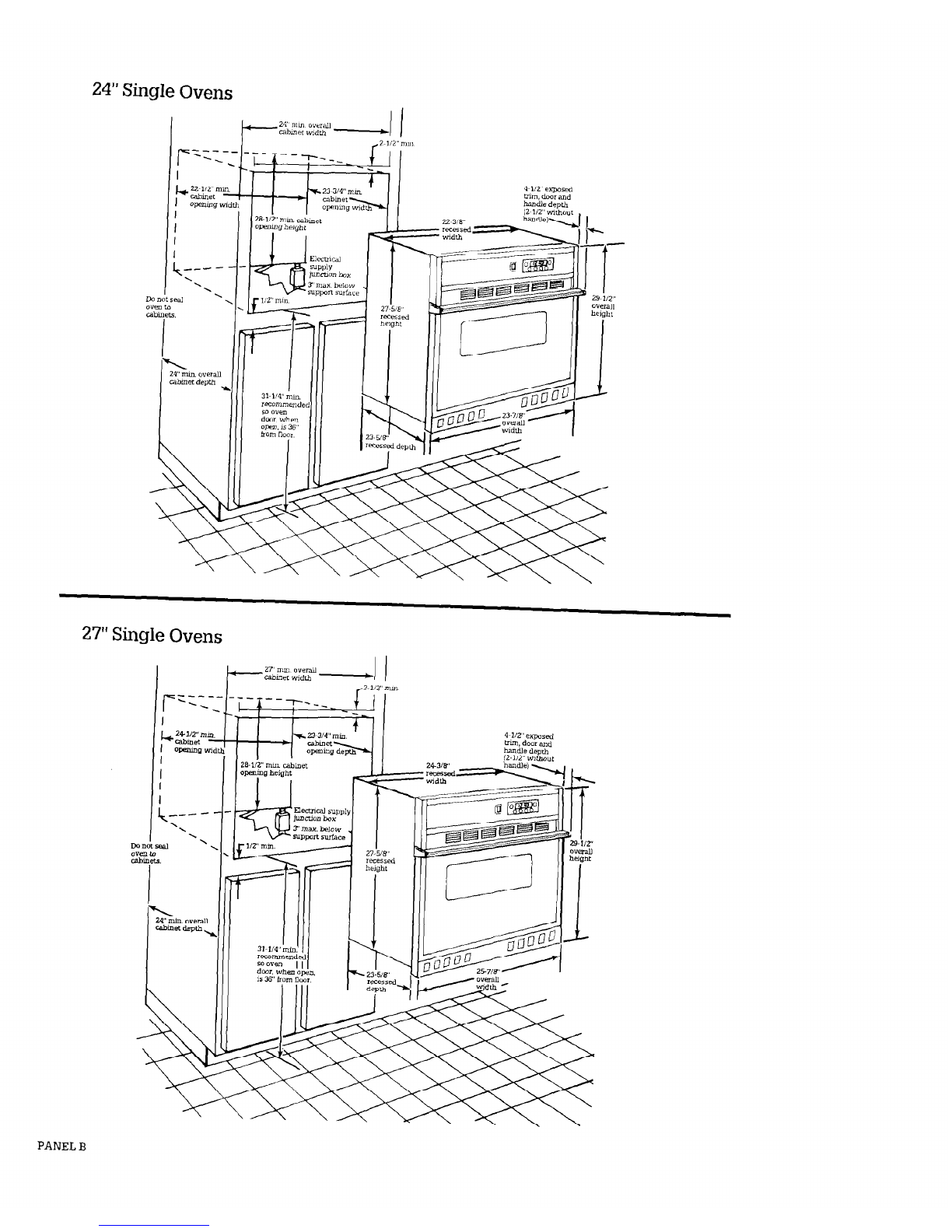
Roper Double Oven User manual

Electric Built-in
27”and24”Single
andDoubleOvens
ROPER””
Appliances
IMPORTANT:
Read and save
these instructions.
IMPORTANT:
Installer: Leave Install~ilor~ Instructions with the homeowner,
Homeowner: Keep Inslal!;t!o~~ kstructlonsfor future reference
Save Installation Icstruclions for local electrical inspector’s use.

24” Double Ovens Before you start...
Read Electrical and Carpentry instructions
Proper mstaLlatmn1syour responslb&y A
quahfled technman should mstall this oven
Make sure you have everythmg necessary for
correct 1nstaUat1on
Check location where the built-m oven wll be
mstalled The locatlon should be away from
strong draft areas, such aswmdows. doors,
and strong heatmg vents 01fans The built-m
oven should be located for convenient use m
htchen.
Cabinet opening djmensions that are shown
must be used. Given chmenslonsprovide
mmunumclearance Contact surface must be
sohd and level
The recessed installation area must prowde
complete enclosure around the recessed
ponlon of the oven
ALL OPENINGSIN THE WALL ORFLOOR
WHERETHE BUILT-IN OVEN ISTO BE
INSTALLED MUSTBESEALED
Electrical ground ISrequired SeeElectrical
requremenls
The oven suppon surface must be flush
with the bottom of the cabinet cutout.
Note:
Clearances specified are for combustible
walls and materials that have a density
of 20or more pounds per cubic foot. No
evaluation of clearances has been made
for installations adlacent to materials
that are less than 20pounds per cu. ft. or
to plastic tiles and sheeting.
Important: Observe all
governing
codes and ordinances.
I
Personal Injury Hazard
Securely fasten wall oven to cabinets I
using the screws provided (4screws for
a double oven or 2screws for a single
oven).
Failure to do socould cause oven to
move or tip during use and result in
personal injury.
27” Double Ovens
Do Not block the oven vent.
Blocking the vent may cause cabinet
damaqe and uoor bakino Derformancc.
Electrical Shock Hazard
It is the customer’s responsibilrty:
’ To contact a quahhed electrical
~ installer.
’ To assure that the electrical installation
is adequate and in conformance with
National Electrical Code, ANWNFPA
70.latest edition’, and all local codes
and ordinances.
Failure to do so could result in fire,
electrical shock or other personal injury.
Tools needed for
installation:
Parts rovided for
instal ation:
f 63
PANEL A

24”
Single Ovens
27”
Single Ovens
PANEL B

Electrical
requirements
Electrical ground is required
on this appliance.
Electric Shock Hazard
. Check with a qualified
electrician if you are in doubt as
to whether the appliance is
properly grounded. Improper
connection of the equipment-
grounding conductor line can
result in a risk of electrical
shock.
- Do Not use an extension cord
with this appliance. Suchuse
may result in a fire. electrical
shock or other personal injury.
* Do Not have a fuse in the neutral
or grounding circuit.
A fuse in
theneutral or grounding circuit
could result in an electrical
shock.
Failure to follow these instruction!
could result in a fire. personal
injury, or electrical shock.
SaveInstallation Instructions for
the local electrical inspector’s use.
A
Ths apphancemust be
n
connected to the proper
electrical voltage and frequency as
specified onthe seritiratmg plate
Models rated at 70kw on 240volts
(53kw on 208volts) 01more require a
separate 40.amperecrcuit Models
rated at 36 !-xvon 240volts (2.7kw
on
208volts) or less requne aseparate
30.amperecmxut. Fuse both sides of
the lme A tune-delay [use or cmxt
breaker ISracormmended
B
OVENMUSTBE CONNECTED
. WI’IH COPPERWIREONLY
C
Wire sizes must conform to
m the recruements of the
NatIonal Elect&l Code,ANSL+JFPA
70.latest edmon’, and all local codes
andordumnces for the kilowatt rating
of the oven. This rating canbe found
on the serial’ratmg plate behmd the
oven door on the front frame.
D
This apphance should be
9 connected to th.efused
chsconma (or Cmxt breaker) box
through flexible armored or
non-metalhc,sheathed copper cable
fwlth aroundma wre) Theflexible
&m&d cable &ten&g from the
apphanceshould be connected duectly
lo the junction box
E
Locate the lunctlon box to
. aLlowas much slack in the
cable aspossible between the
lunctlon box and the apphanceso that
the oven can be moved ti servlcmg is
ever needed
F
A U.L -hsted condux connector
must be provided at the
’ ~unctlonbox
G It 1stte personal
n
responsiblbty and obhgation
of the customer to contact a quahfled
elennclan to assure that the klectrical
mstallatmn ISadequate and is m
conformance with the National
E!ectncal CodeANSI/NFPA 70.latest
edItIon*, and aL’local codes and
ordmmces
H
A wrong dagram is mcluded
mm the Tech sheet. The Tech
sheet1slocated oehmd the control
panel
Electrical
connection
Electrical ground is required
on this appliance.
4. Connect the groundmg wue to a
grounded wire 111the ]unct~onbox or to
a grounded, copper cold water Pipe **
Electrical Shock Hazard
- Do Not connect appliance to
electrical supply until appliance
is permanently grounded.
l
Disconnect power to the
junction box before making the
electrical connection.
n
This appliance must to
connected to a grounded.
metallic. permanent wiring
system, or a grounding
conductor should be connected
to the grounding terminal of
lead on the appliance.
I
Failure to follow these
I
jnstructions could result m a fire.
personal injury, or electrical
shock.
Tbs apphance 1smanufactured wxh
white (neutral) power supply wre and
a cabmet-connected. green groundmg
wre (green twisted together)
Connect the apphance cable to the
lunctmn box through the U L -hsted
conduit connector. Complete
electrical connection accordmgto your
mstallatmn needs
A. Where local codes
permit...
connecting the cabinet-grounding
conductor to the neutral (white)
junction box wire:
Figure 1
1.Turn power supply off
2.Connect three wires green and
whte apphance cable wLies with the
neutral (wtite) wne m junction box
3. Connect the two black wues
together, then the two red wues
together (SeeFigure 1)
B. Where local codes
DO NOT permit...
connecting the cabinet-grounding
conductor to the neutral (white)
junctmn box wire:
Figure 2
1. Turn power suppiy off
2. Connect the white apphancecable
wue to the neutral (whxe) wue m
]unctlon box
3. Connect the two black wres
together; then the two red wnes
together (SeeFigure 2)
Figure 3
5. A separate copper groundmg wxe
(No. 10mmmum) MUST be connected
to a grounded metal cold water pipe by
meansof a clamp and then to the
external groundmg mnnector screw.
Do Not ground to a gas
supply
pipe
or hot water pipe. Do Not connect
to electrical supply until appliance 1s
permanently grounded. (See
Figure 3 )
C. IF connecting to a
four-wire electrical
system...
DONOT connect the cabinet-
grounding conductor to the neutral
(white) junction box wire.
Figure 4
1. Turn power supply off
2. Separate the green and wtite
appbancecable wues
3. Connect the white apphance cable
wue to the neutral (wtite) wre m
iuncilon box
4. Connect the two black wires
tooether. then the two red wres
together (SeeFigure 4.)
5. Connect the green apphance cable
wre to green groundmg wxe in the
]unctlon box
PANEL C

Now start...
With oven in kitchen.
1
Re.nove stippmg materials,,
mtape and protectwe film from
wall oven. Do NoI remove the foam
shipping base at this time.
2
Removeracks and other parts
n
from mslde oven. Removethe
au grille taped to the top OIside
of oven
3
Complerely o*en lower oven
n
door Removethe two oven
door mews (Not all models have
oven door screws )
6
Personal Injury/Product Damage
’ Use both hands to remove oven
doors.
’ Grasp only the sides of rhe oven
door. Do Not use any portion 01
the lronr lrames or trim for
lifting.
Failure to properly grasp oven
door could result in damage fo
product or personal injury.
6
Turn power supply off Move
. oven close to final posmon
Removeand dmard foam shlppmg
base.Feed apphaace cable through
opemng mcabmet. Make electrical
conmxt~om SeeElectrical
remurements and Electrical
connection sectlom, Panel B.
Product Damage
Carefully push against seal area of
the front frame when pushing
oven into cabinet. Do Not push
againstourside
edges.
Failure to follow this instruction
can result in damage to the
porcelain finish.
._
4
Closelower oven door LOthe
n
broil posltlon Grasp the sides
of the oven door and pull the door up
and out of hmge slots to remove Set
door aslde
5
Repeat Steps 3and 4 for upper
. oven door
Floor Damaae
6.
Numbers
correspond
to steps.
PANEL D

Personal Injury/Product Damage
Securely fasten oven to cabinets
using the four screws provided.
Failure to
do
socould cause the
oven to move or tip during use
and result in
personal injury or
product damage.
8
Center oven mto cabmet
n
cutout Usetwo screws (four
screws for a double oven) through the
mountmg holes mthe front frame of
the oven to secure the oven to the
cabmet Do Not overtlghten screws
3°C “se the one.
-b low prollle screw
in ml Posltmn
9
InstaUlower air grille usmg the
. three sxews provided.
10
Replacethe oven racks
. Replaceupper oven door by
pW.laLlyflttmg the door hinges mto the
hmge slots FuLldoor shghtly toward
you, then shde door completely m place
Remstall the two oven~doorscrews (lf
rec;ured for your oven door) If door does
not close, you have not pushed hmges
complete!y ml0 frame Repeat for lower
oven door Turn power supply on
11
Check the operation of the
n
upper (01single) oven.
Push‘Bake’ button. ‘- __ “F” will appear
mthe dxplay and the “Bake”hght will
comeon. Press“Bake”button until 350°F
appears m the &splay The bottom and
uoper. outer elements should alow red
The upper (or smgle) oven ‘on”mdlcator
hght should be on and the oven should
be heatma. Pushthe cancel button The
tnne of day should appear III the display.
Check the operation of the lower oven.
Setthe lower oven control knob to
350°F The bottom and upper, outer
elements should glow red The lower
oven mdlcator haht should be on and
the oven shouldbe heatmg Turn the
control knob to “OFF”
12
Check the operation of the
l
upper (or single) oven broil
element. Pushthe “Broil” bu!ton “__-”
will appear m the display and tne “Broil’
uxhcator hghr wLLlcome on Turn oven
control knob until “HI Broil aDoearsm the
&splay Both lop elemerlts sh&ld glow
red The upper (or smg;e)oven “On”
mdlcator hght should be on and the oven
should be hentmo Pushthe cancel button
The time of day should appear m the
dlsp1ay
Check the weration of the lower oven
Setthe low& oven 10m;)2:i.tu1eConlTol
k11obto ‘Broil” The top, !m:er elements
should
QlOW
red The lower ovci, mdxator
huh1should be on
and
the oven should be
Congratulations!
Youhave just finished
installing your II~W.
Roper oven. Keep Installation
Instructions available for
easy reference.
PANEL E
Table of contents
Other Roper Oven manuals

Roper
Roper BGC430W BGP430W User manual

Roper
Roper B8758B0 User manual

Roper
Roper B400 User manual

Roper
Roper Roper BES450WB1 User manual

Roper
Roper B9758B0 User manual

Roper
Roper Convection Oven User manual

Roper
Roper B4007B0 User manual

Roper
Roper B9907X0 User manual

Roper
Roper ELECTRIC DROP-IN D975 User manual

Roper
Roper B4607B0 User manual