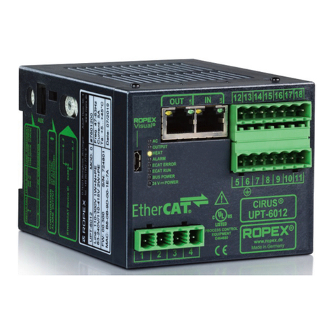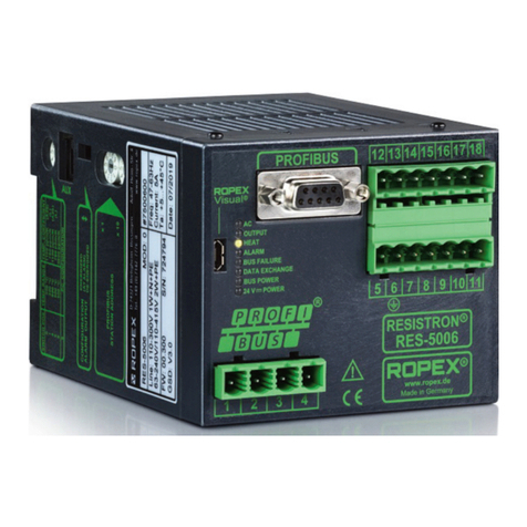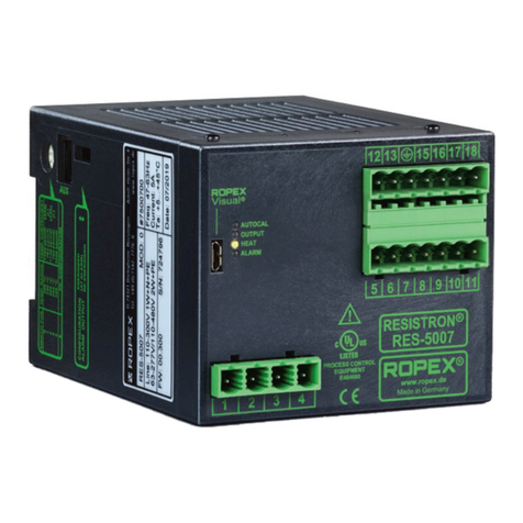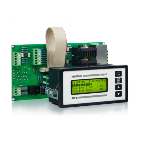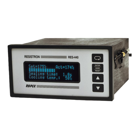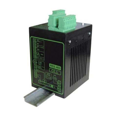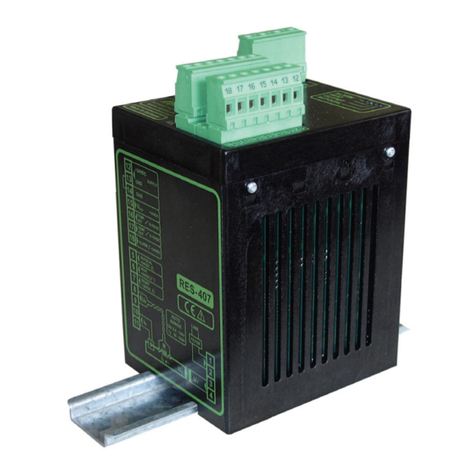
Page 2 RES-5008 Version 2
Table of contents
1 Revision List . . . . . . . . . . . . . . . . . . . . . . . . 4
2 General information . . . . . . . . . . . . . . . . . . 4
2.1 Use of the operating instructions . . . . . 4
2.2 Drawings and illustrations . . . . . . . . . . 4
2.3 Copyright . . . . . . . . . . . . . . . . . . . . . . . 4
3 Safety . . . . . . . . . . . . . . . . . . . . . . . . . . . . . . 4
3.1 Warning notices in the operating
instructions . . . . . . . . . . . . . . . . . . . . . 4
3.2 General safety information . . . . . . . . . 6
3.3 Intended Use . . . . . . . . . . . . . . . . . . . . 6
3.4 User qualifications . . . . . . . . . . . . . . . . 6
3.5 DECLARATION OF CONFORMITY . . 7
4 Requirements for the functioning of the con-
trol system . . . . . . . . . . . . . . . . . . . . . . . . . . 8
4.1 Heating element . . . . . . . . . . . . . . . . . 8
4.2 Impulse transformer . . . . . . . . . . . . . . 9
4.3 Current transformer . . . . . . . . . . . . . . . 9
4.4 Line filter . . . . . . . . . . . . . . . . . . . . . . . 9
4.5 Application report . . . . . . . . . . . . . . . . 9
5 Product description . . . . . . . . . . . . . . . . . . 10
5.1 Use . . . . . . . . . . . . . . . . . . . . . . . . . . 10
5.2 Functional principle . . . . . . . . . . . . . . 11
5.3 Regulator features . . . . . . . . . . . . . . . 11
6 Transport and Storage . . . . . . . . . . . . . . . 12
6.1 Scope of Delivery . . . . . . . . . . . . . . . 12
6.2 Transport and Storage . . . . . . . . . . . 12
7 Mounting and Installation . . . . . . . . . . . . . 12
7.1 Installation sequence . . . . . . . . . . . . . 12
7.2 Installation notes . . . . . . . . . . . . . . . . 14
7.3 Mains connection . . . . . . . . . . . . . . . 15
7.4 Line filter . . . . . . . . . . . . . . . . . . . . . . 16
7.5 Current transformer . . . . . . . . . . . . . . 16
7.6 Circuit diagram (standard) . . . . . . . . . 18
7.7 Circuit diagram with booster
connection . . . . . . . . . . . . . . . . . . . . . 19
8 Commissioning and operation . . . . . . . . . 20
8.1 Device view . . . . . . . . . . . . . . . . . . . . 20
8.2 Device configuration . . . . . . . . . . . . . 20
8.3 Burning in and changing the heating
element . . . . . . . . . . . . . . . . . . . . . . . 22
8.4 Commissioning rules . . . . . . . . . . . . . 24
9 Device functions . . . . . . . . . . . . . . . . . . . . 26
9.1 Display elements and operating
elements . . . . . . . . . . . . . . . . . . . . . . 26
9.2 Display image of the T-408-1 terminal 27
9.3 Menu navigation . . . . . . . . . . . . . . . . 28
9.4 Menu structure . . . . . . . . . . . . . . . . . . 29
9.5 Menu items . . . . . . . . . . . . . . . . . . . . 30
9.6 Temperature setting (setpoint
specification) . . . . . . . . . . . . . . . . . . . 31
9.7 Temperature display/Actual value
output . . . . . . . . . . . . . . . . . . . . . . . . . 31
9.8 Automatic zero calibration
(AUTOCAL) . . . . . . . . . . . . . . . . . . . . 33
9.9 Heating up to the sealing temperature
(HEAT) . . . . . . . . . . . . . . . . . . . . . . . . 34
9.10 Preheating (PREHEAT-Signal) . . . . . 34
9.11 Hold mode . . . . . . . . . . . . . . . . . . . . . 36
9.12 Temperature unit Celsius/Fahrenheit 37
9.13 Measurement impulse duration . . . . . 40
9.14 Automatic phase correction
(AUTOCOMP) . . . . . . . . . . . . . . . . . . 40
9.15 Temperature diagnosis . . . . . . . . . . . 42
9.16 Heat-up time monitoring . . . . . . . . . . 43
9.17 Restart delay after Reset . . . . . . . . . . 43
9.18 Maximum measurement pause . . . . . 44
9.19 Communication failure between controller
and terminal . . . . . . . . . . . . . . . . . . . . 44
9.20 Undervoltage detection . . . . . . . . . . . 44
9.21 Booster connection . . . . . . . . . . . . . . 45
9.22 USB-interface for visualisation software
ROPEXvisual®. . . . . . . . . . . . . . . . . . 45
9.23 AUX interface . . . . . . . . . . . . . . . . . . 46
9.24 System monitoring/alarm output . . . . 46
9.25 Error messages . . . . . . . . . . . . . . . . . 48
9.26 Error areas and causes . . . . . . . . . . . 53
9.27 Measures in the event of an error . . . 54
