Ros SEASTAR User manual

10-01313 REV D
OPERATION AND MAINTENANCE MANUAL
Remote Ocean Systems claims proprietary rights to the information disclosed herein. This
document is furnished in confidence on the express understanding that neither it nor any
reproduction thereof will be disclosed to others or used for the purpose of manufacture
or procurement. Approved for internal release only. Distribution is limited.
© 2021 Remote Ocean System

REMOTE OCEAN SYSTEMS SEASTAR OPERATION AND MAINTENANCE MANUAL
10-01313 REV D
2
Contents
WARRANTY ...................................................................................................................................................4
Customer Assistance......................................................................................................................................5
Change Record...............................................................................................................................................6
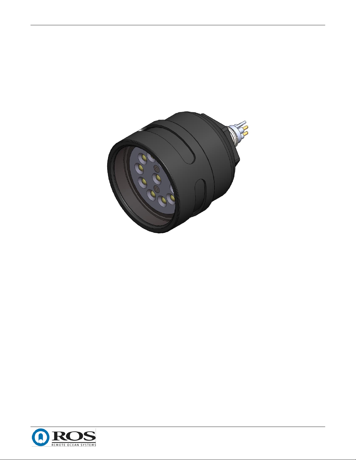
1. Introduction...............................................................................................................................................7
2. Product Specifications................................................................................................................................8
3. Installation...............................................................................................................................................10
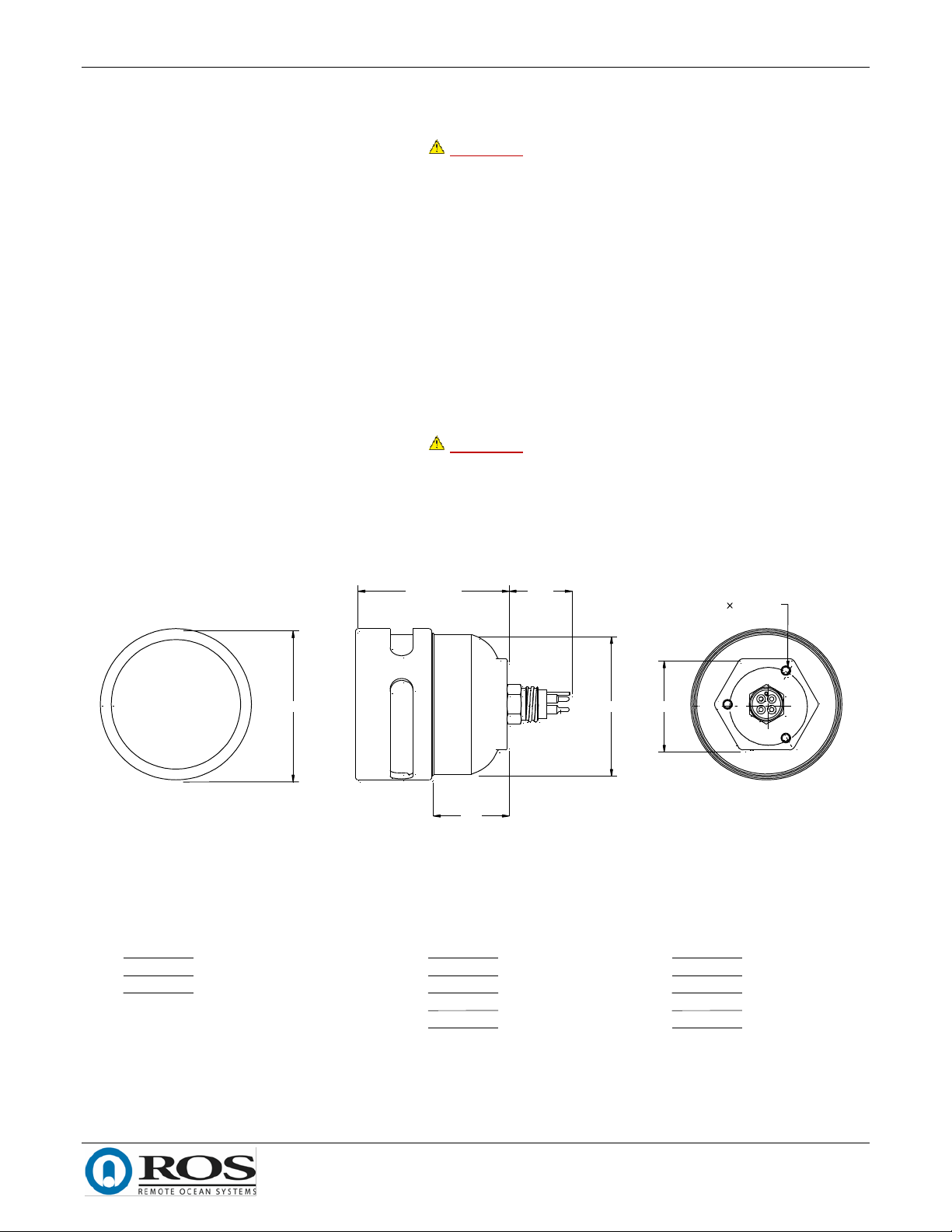
3.1. Mounting...................................................................................................................................................... 10
3.2. Electrical....................................................................................................................................................... 10
4. Operation ................................................................................................................................................11
4.1. Pre-Operation............................................................................................................................................... 11
4.2. Post Operation ............................................................................................................................................. 11
4.3. AC Operation................................................................................................................................................ 11
4.3.1. AC Triac Dimming .................................................................................................................................. 11
4.3.2. AC Crydom Dimming ............................................................................................................................. 12
4.3.3. AC Inrush Current.................................................................................................................................. 13
4.4. DC Operation................................................................................................................................................ 13
4.4.1. Analog Dimming .................................................................................................................................... 13
4.4.2. Serial Dimming Operation ..................................................................................................................... 14
4.4.3. DC Inrush Current.................................................................................................................................. 17
4.5. Temperature Protection .............................................................................................................................. 18
4.5.1. 120VAC .................................................................................................................................................. 18
4.5.2. 24VDC .................................................................................................................................................... 18
4.6. Electrical Protection..................................................................................................................................... 18
4.6.1. 24VDC .................................................................................................................................................... 18
5. Maintenance............................................................................................................................................19
5.1. Scheduled Maintenance............................................................................................................................... 19
5.2. Unscheduled Maintenance .......................................................................................................................... 19
5.2.1. Open the Seastar................................................................................................................................... 19
5.2.2. Close the Seastar ................................................................................................................................... 20
5.2.3. Remove the Reflector and LED Array .................................................................................................... 21
5.2.4. Replace the Window, Reflector and LED Array..................................................................................... 22
5.2.5. Replace the Connector .......................................................................................................................... 23
5.2.6. Remove and Replace the Driver Circuit Card ........................................................................................ 24
6. Troubleshooting.......................................................................................................................................27
6.1. Leaking ......................................................................................................................................................... 27
6.2. Light Output Gradually Decreased............................................................................................................... 27
6.3. Light Flickers or Intermittently Stops........................................................................................................... 27
6.4. Light Output Suddenly Stopped................................................................................................................... 28
6.5. Serial Light Does Not Respond to Commands.............................................................................................. 30
7. Parts List..................................................................................................................................................31

REMOTE OCEAN SYSTEMS SEASTAR OPERATION AND MAINTENANCE MANUAL
10-01313 REV D
3
Figures
Figure 1. Seastar.........................................................................................................................................................7
Figure 2. Beam Patterns .............................................................................................................................................9
Figure 3. Installation Outline................................................................................................................................... 10
Figure 4. Sample Wiring .......................................................................................................................................... 10
Figure 5. AC Lux Output with Triac Dimming .......................................................................................................... 12
Figure 6. AC Lux Output with Crydom Dimming...................................................................................................... 12
Figure 7. AC Inrush Current ..................................................................................................................................... 13
Figure 8. Lux Output vs Analog Dimming Percent................................................................................................... 14
Figure 9. Lux Output vs Serial Dimming Percent..................................................................................................... 15
Figure 10. DC Inrush Current................................................................................................................................... 17
Figure 11. Driver Circuit Card Connections ............................................................................................................. 20
Figure 12. Closing the Seastar ................................................................................................................................. 21
Figure 13. Window, Reflector and LED Array Replacement.................................................................................... 22
Figure 14. Top Layer 120VAC Driver Board ............................................................................................................. 24
Figure 15. U4 on Top Layer 24VDC Driver Board .................................................................................................... 25
Figure 16. Q1 on Bottom Layer 24VDC Driver Board .............................................................................................. 25
Figure 17. AC Driver Circuit Card Replacement....................................................................................................... 26
Figure 18. Connections............................................................................................................................................ 28
Figure 19. Driver Input and Output Power Pins ...................................................................................................... 30
Figure 20. Front Explode View................................................................................................................................. 32
Figure 21. Back Explode View.................................................................................................................................. 32
Tables
Table 1. Mechanical Specifications.............................................................................................................................8
Table 2. Electrical Specifications ................................................................................................................................8
Table 3. Serial Parameters....................................................................................................................................... 15
Table 4. Serial Commands and Inquiries ................................................................................................................. 15
Table 5. Serial Response Messages ......................................................................................................................... 17
Table 6. Threads Size vs. Recommended Torque.................................................................................................... 24
Table 7. Bill of Materials.......................................................................................................................................... 31
Table 8. Rebuild Kits ................................................................................................................................................ 33

REMOTE OCEAN SYSTEMS SEASTAR OPERATION AND MAINTENANCE MANUAL
10-01313 REV D
4
WARRANTY
ROS, Inc. (hereinafter called "ROS") warrants its products as stated below subject to the conditions specified.
ROS warrants its products, when operated under normal conditions, to be free from defects in material or
workmanship for a period of one year from the date of purchase provided that inspection by ROS discloses that
such defects developed under normal and proper use. ROS products repaired or replaced pursuant to this
warranty shall be warranted for the unexpired portion of the warranty applying to the original product. The
liability of ROS under this warranty shall exist subject to the following conditions:
(a) Purchaser properly notifies ROS of such defects and the defective product is returned to ROS;
transportation charges paid by Purchaser.
(b) ROS shall be released from all obligations under its warranty in the event repairs or
modifications are made by persons not authorized by ROS.
(c) Representations and warranties made by any person, including distributors and representatives
of ROS, which are inconsistent or conflict with the terms of this warranty, shall not be binding
upon ROS unless reduced to writing and approved by an officer of ROS. ROS shall in no event be
liable for other direct, special, incidental, consequential, indirect or penal damages.
(d) The laws of the State of California shall govern this warranty.
In the event the defect is determined to be within the terms of this warranty then ROS agrees to repair and/or
replace (at ROS' discretion) the product or defective portion at no charge to the Purchaser. This warranty does
not apply to expendable items or to normal wear-and-tear, and is conditional upon performance of normal
preventative maintenance procedures.
Our commitment to quality and customer service directs us to constantly strive to improve our products. The
materials and specifications presented in our manuals and data sheets are correct and accurate to the best of
our knowledge, and are presented in good faith. However, the information is not guaranteed and is subject to
change without notice.
LIMITATIONS OF REMEDIES
Purchaser assumes all risk and liability for results obtained in any installation, operation, or use of the product.
Purchaser’s sole remedy for any breach of warranty by vendor shall be limited to the “express remedies” set
forth above. Otherwise, in no event shall vendor, its agents, or employees be liable to the original purchaser or
any third party for any consequential or incidental damages or expenses of any nature arising directly out of or
in connection with the use of vendor projects, even if vendor has been advised of the possibility of such
damages or expenses. In any event, unless otherwise contrary to state law, vendor liability under this limited
warranty shall not exceed the purchase price of the product.

REMOTE OCEAN SYSTEMS SEASTAR OPERATION AND MAINTENANCE MANUAL
10-01313 REV D
5
Customer Assistance
ROS, Inc. uses a worldwide network of stocking distributors and representatives who are familiar with our
products and are able to provide assistance during installation and/or operation of these products.
If you have any questions or problems with this product that are not covered by this manual or instruction,
please contact our agent in your area, or contact us directly by phone or FAX or e-mail.
TEL: (001) 858-565-8500
FAX: (001) 858-565-8808
Sales: [email protected]m
Web Site: www.rosys.com
Technical Support: support@rosys.com

REMOTE OCEAN SYSTEMS SEASTAR OPERATION AND MAINTENANCE MANUAL
10-01313 REV D
6
Change Record
REV DESCRIPTION DATE
A SEE EC-03199 08JUN20
B SEE EC-03210 18JUN20
C SEE EC-03228 20AUG20
D SEE EC-03358 03MAY21

REMOTE OCEAN SYSTEMS SEASTAR OPERATION AND MAINTENANCE MANUAL
10-01313 REV D
7
1. Introduction
The Seastar (Figure 1) is a high-powered, light-weight, compact light for deep-ocean use. Options include flood
or spot reflectors, and 120 VAC or 24 VDC power. AC powered lights provide full-range, flicker-free phase cut
dimming. DC lights provide dimming via 0 –10 V analog, 0 –5 V analog, or RS48 serial commands. Custom input
connectors and pinouts may be specified. The light may be installed at any angle.
Figure 1. Seastar

REMOTE OCEAN SYSTEMS SEASTAR OPERATION AND MAINTENANCE MANUAL
10-01313 REV D
8
2. Product Specifications
Table 1 shows the mechanical specifications for the Seastar. Table 2 shows the electrical specifications. Figure 2
shows the spot and flood beam patterns.
Table 1. Mechanical Specifications
Spot
Wide
Weight in air
1.9 lb (.86 kg)
1.8 lb (.81 kg)
Weight in water
1.0 lb (.41 kg)
.91 lb (.45 kg)
Depth rating
20,000 ft (6 km)
Operating temp
-10 to 40°C
Storage temp
-25 to 100°C
Light output
9,000 lux
10,000 lm
Beam angle (50%)
50°
105°
Table 2. Electrical Specifications
AC
DC
Voltage
110 –130 VAC
20 –26 VDC
Current
1.3 A
6.0 A
Inrush current
2.5 A, 10 ms
27 A, 1 ms
Color temperature
6300 K
Color rendering index
65

REMOTE OCEAN SYSTEMS SEASTAR OPERATION AND MAINTENANCE MANUAL
10-01313 REV D
9
Figure 2. Beam Patterns

REMOTE OCEAN SYSTEMS SEASTAR OPERATION AND MAINTENANCE MANUAL
10-01313 REV D
10
3. Installation
WARNING
The Seastar is an industrial product designed for use in rugged underwater
environments. The Seastar installation and power system should be designed by
a qualified engineer and installed by qualified technicians.
3.1. Mounting
Figure 3 shows the outline of the Seastar. If an ROS provided mounting kit is not used, the Seastar may be
mounted by clamping the body of the light or using the three, 10-32 holes in the end bell. It is not recommended
to clamp to the bezel of the light.
3.2. Electrical
The Seastar pinout will depend on customer selections; Figure 4 shows the default wiring. The ground pin should
be wired to earth ground.
WARNING
The Seastar should be operated only through a circuit with ground fault
interrupt protection.
REM OTE OCEAN SYSTEM S CLAI M SPROPRI ETARY RI GHTS TO THE
I NFORM ATI ON DI SCLOSED HEREI N. THI S DOCUM ENT I S FURNI SHED I N
CONFI DENCE ON THE EXPRESS UNDERSTANDI NG THAT NEI THER I T NOR
ANY REPRODUCTI ON THEREOF W I LL BE DI SCLOSED TO OTHERS OR
USED FOR THE PURPOSE OF M ANUFACTURE OR PROCUREM ENT.
APPROVED FOR I NTERNAL RELEASEONLY. DI STRI BUTI ON I S LI M I TED.
NOTES: UNLESS OTHERW ISE SPECIFIED
1. M ATERIAL:
HOUSING:ALUM INUM 6061-T6
ENDBELL:ALUM INUM7075-T6
BEZEL:ALUM INUM 6061-T6
WINDOW: PLEXIGLAS G
2. FINISH: HARD ANODIZE, BL ACK
3. DEPTHRATING:20,000 ft(6 km )SEAWATER
4. WEIGHT AIR / W ATER:
SPOT:1.9 /1.0 lb (.86 / .45 kg)
FLOOD:1.8 /.91 lb(.81 /.41 kg)
5. M INIM UM LIGHT OUTPUT:
SPOT:9,000 lx
FLOOD:3,600 lx,10,000 lm
6. BEAM ANGLE AT50% INTENSITY
SPOT:38°
FLOOD:110°
7. OPERATIONALTEM P: 40 °C.SELF-DIM M INGTHERM AL PROTECTIONABOVE 40 °C
8. POWER:
120 VAC,1.0 A
24 VDC,4.6 A
9. DIM M INGOPTIONS:
AC:PHASE CUT DIM M ING
DC:RS485,0 -5 V,0 -10 V
10. DEPENDINGON CUSTOM ER SELECTABLE CONNECTOR.
C
B
AA
B
123
45
6
7
8
8765 4 3 2 1
C
D
SHEET 1 O F 2SCALE: NO NE
REVDWG . NO .
D
SI ZE
TI TLE:
1+
CAG E
10-01314
NEXT ASSY USED O N
2T637
D
APPRO VALS
APPLI CATI O N
APPRO VED
M . POGUE
APPRO VED
CHECKED
DRAW N
DATEUNLESS O THERWI SE SPECI FI ED
DI M ENSI O NI NG AND TO LERANCING I AW ASM E Y14. 5 2009
•DI M ENSI O NS ARE I N I NCHES•TO LERANCES: ANG LES±1°• .XXX±. 005
. XX±.01
.X±.03
REM O VE BURRS AND BREAK SHARPEDG ES .015 M AX•UNSPECI FI ED RADI I . 015 M AX
•M ACHINE TO O L M ISM ATCH.003 M AX•
SURFACE TEXTURE: 63
•
SEASTAR - INSTAL LATION AND
OUTL INE
17OCT19
PROTOTYPE
REVISIONS
REV DESCRIPTION
EC NO.
DATE APPROVED
Ø3.31
3.31 FLOOD
3.55 SPOT 1.375
Ø3.05
1.66
2.00
Ø3X10-32 UNF -2B .25 DEEP
DEPENDINGON
CONNECTOR
Figure 3. Installation Outline
1 EARTH GROUND
2 120 VAC, 1P, 1.5 A SUPPLY
3 120VAC RETURN / NEUTRAL
AC WIRING
1 EARTH GROUND
2 24VDC,5A SUPPLY
3 24VDC RETURN
DC SERIAL
4 RS485 +
5 RS485 -
1 EARTH GROUND
2 24VDC,4A SUPPLY
3 24VDC RETURN
0 - 10 (0 - 5) V DIMMING
4 0-10 (0-5) V+
5 0-10 (0-5) V -
Figure 4. Sample Wiring

REMOTE OCEAN SYSTEMS SEASTAR OPERATION AND MAINTENANCE MANUAL
10-01313 REV D
11
4. Operation
4.1. Pre-Operation
Prior to operating the Seastar, perform the following.
1. Verify the bezel cannot be rotated by hand.
2. Verify the window is tightly held by the bezel.
3. Verify the window o-ring is evenly compressed by the window.
4. Verify the connector is clean, dry (if dry mate) and in good repair.
5. Verify the power cable is securely connected.
4.2. Post Operation
After operating the Seastar, perform the following.
1. Rinse the light with clean water and remove any salt or fouling.
2. Inspect the exterior light for overt signs of damage.
4.3. AC Operation
Check the part number of the Seastar unit and see below for proper operation.
10-01310 (-03)
This version is only compatible for operation with a Schilling Light Control Unit (LCU). The dimming mechanism
of the light takes advantage of the rectified AC output from the LCU to achieve low light levels at the lower end
of the dimming range. Use LCU application to turn on the light, the corresponding slider will determine the light
output intensity. DO NOT PLUG DIRECTLY INTO WALL OUTLET, the unrectified AC sine wave will damage the
driver board.
10-01310 (-01, -02,-04)
These versions are compatible for operation with a standard phase control dimmer such as a TRIAC or Crydom
dimmer, they can also be plugged directly into a 120VAC wall outlet for 100% light output.
10-01317 (-03,-06)
These versions will only operate when using an isolated 0-10VDC voltage supply to control the light output
intensity. Light output will be at 0% if only load, neutral, or earth ground are connected, or if the voltage supply
is set to 0VDC. To change the light output intensity adjust the voltage supply between between 0-10VDC, with
10VDC setting the light output to 100% intensity.
4.3.1. AC Triac Dimming
Figure 5 shows the Seastar light output when used with a triac dimmer. The test was performed using a Lutron
DVCL-153P-WH dimmer.

REMOTE OCEAN SYSTEMS SEASTAR OPERATION AND MAINTENANCE MANUAL
10-01313 REV D
12
Figure 5. AC Lux Output with Triac Dimming
4.3.2. AC Crydom Dimming
Figure 6 shows the Seastar light output when used with a Crydom dimmer. The test was performed using a
10PCV2415 Crydom dimmer.
Figure 6. AC Lux Output with Crydom Dimming

REMOTE OCEAN SYSTEMS SEASTAR OPERATION AND MAINTENANCE MANUAL
10-01313 REV D
13
4.3.3. AC Inrush Current
Figure 7 shows the inrush current for the AC light at 120VAC input.
Figure 7. AC Inrush Current
4.4. DC Operation
The DC light will work with 20 –26 VDC input. The light output will vary with input voltage. The DC light has
been optimized for use with 24VDC input. The DC light can be configured for 0-5VDC, 0-10VDC, or RS485
control.
Check the part number of the Seastar unit and see below for proper operation.
10-01341 (-01)
This version is a 24VDC low power light controlled by a 0-5VDC voltage supply, with max power of 21W.
10-01317 (-01)
This version is a 24VDC standard power light controlled by half duplex RS485, with max power of 130W.
10-01317 (-02)
This version is a 24VDC standard power light controlled by 0-5VDC voltage supply, with max power of 130W.
10-01317 (-03)
This version is a 24VDC standard power light controlled by 0-10VDC voltage supply, with max power of 130W.
4.4.1. 24VDC With Analog Dimming
Figure 8 shows the Seastar dimming properties when used with a 0-5V or 0-10V analog dimmer.

REMOTE OCEAN SYSTEMS SEASTAR OPERATION AND MAINTENANCE MANUAL
10-01313 REV D
14
Figure 8. Lux Output vs Analog Dimming Percent
4.4.2. 24VDC With Serial Dimming Operation
Figure 9 shows the light’s dimming properties when used with RS485 control. The serial-dimming Seastar can be
operated using the ROS Eos GUI, or by sending serial commands from a customer device or software. Table 3
lists ROS VISCA serial parameters. Table 4 lists commands and inquiries that may be sent to the Seastar, along
with their expected responses. Table 5 lists standard response messages.
NOTE
All serial commands, inquiries and responses are terminated with hex byte ff
(255).

REMOTE OCEAN SYSTEMS SEASTAR OPERATION AND MAINTENANCE MANUAL
10-01313 REV D
15
Figure 9. Lux Output vs Serial Dimming Percent
Table 3. Serial Parameters
Baud Rate
9600
Data bits
8
Start bits
1
Stop bits
1
Parity
None
Flow control
None
Table 4. Serial Commands and Inquiries
Command
Packet
Note
Set Address
88 30 0x ff
x = address 1 - 7
Returns 88 30 0y
y = x + 1
When setting the address of an ROS VISCA device, any
connected devices will respond, causing collisions.
Consequently, only one device can be connected to a bus
when setting the address.

REMOTE OCEAN SYSTEMS SEASTAR OPERATION AND MAINTENANCE MANUAL
10-01313 REV D
16
Table 4. Serial Commands and Inquiries
Command
Packet
Note
Set Intensity
8x 01 10 01 yy ff
x = address
yy = Intensity (0x00 –0x64 hex, 0 - 100 decimal)
Returns Command Completed if successful
Set Power Up Intensity
8x 01 10 02 yy ff
x = address
yy = Intensity (0x00 –0x64 hex, 0 - 100 decimal)
Returns Command Completed if successful
Get Factory Info
8x 09 06 50 ff
x = address
Returns comma separated factory information. The first two
bytes are hex, all other bytes are text.
z0 50 [unit pn],[unit rev],[unit sn],[cca pn],[cca rev],[cca
sn],[firmware pn],[firmware rev]
z = address + 8 (byte)
Get Temperature
8x 09 10 03 ff
x = address
Returns z0 10 10 03 0y 0y 0y ff
z = address + 8 (byte)
yyy = Hexadecimal temperature in Kelvin
Get Intensity
8x 09 10 04 ff
x = address
Returns z0 10 10 04 yy ff
z = address + 8 (byte)
yy = Light intensity percent (0x00 –0x64 hex, 0 - 100 decimal)
Get Power Up Intensity
8x 09 10 05 ff
x = address
Returns z0 10 10 05 yy ff
z = address + 8 (byte)
yy = Light intensity percent (0x00 –0x64 hex, 0 - 100 decimal)
Get Error
Status
8x 09 10 06 ff
x = address
Returns z0 10 10 06 0y ff
z = address + 8 (byte)
y = 4 bits:
bit 0 = MOSFET over-current true/false
bit 1 = Driver Output over-voltage true/false
bit 2 = LED over-current true/false
bit 3 = 0

REMOTE OCEAN SYSTEMS SEASTAR OPERATION AND MAINTENANCE MANUAL
10-01313 REV D
17
Table 5. Serial Response Messages
Response
Packet
Note
Command Completed
z0 5y ff
z = address + 8
y = socket (default 1)
Returned when the command has been executed
Syntax Error
z0 60 02 ff
z = address + 8
Returned when the command format is different or when a
command with illegal command parameters is accepted.
Command Not Executable
z0 6y 41 ff
z = address + 8
y = socket (default 1)
Returned when a command cannot be executed due to
current conditions. For example, when user issues a light
intensity command with a value greater than the maximum
allowed value.
4.4.3. DC Inrush Current
Figure 10. shows the inrush current for the DC light at 24VDC input.
Figure 10. DC Inrush Current

REMOTE OCEAN SYSTEMS SEASTAR OPERATION AND MAINTENANCE MANUAL
10-01313 REV D
18
4.5. Temperature Protection
4.5.1. 120VAC
The AC light will reduce the current output of the driver up to half the total value if an overheating condition is
detected by the driver. The light will have to be power cycled to return to normal operation.
4.5.2. 24VDC
The DC light driver will reduce the light output of the driver to 15% of the maximum light output. The user will
not be able to increase the light output until the light driver has detected that the temperature of the board has
gone below approximately 50° Celsius. Once the light driver has gone below 50° Celsius, it will automatically
return to its original light output level.
4.6. Electrical Protection
4.6.1. 24VDC
The DC light driver will stop the light output if it detects a MOSFET over-current, output over-voltage, or an LED
over-current signal. If light is configured for 0-5V or 0-10V control, refer to section 6.4 for troubleshooting. If
light is configured for RS485 control, the user can issue a “Get Error Status”command to check if the driver is in
electrical protection mode.
CAUTION
Complete troubleshooting prior to restoring power to a light that has stopped to
avoid energizing a shorted unit.
The light can be returned to normal mode by power cycling the unit, but refer to section 6.4 prior to doing so to
avoid energizing a shorted unit.

REMOTE OCEAN SYSTEMS SEASTAR OPERATION AND MAINTENANCE MANUAL
10-01313 REV D
19
5. Maintenance
5.1. Scheduled Maintenance
Pre- and post-operation checks are listed in Section 4. No other scheduled maintenance is recommended.
5.2. Unscheduled Maintenance
5.2.1. Open the Seastar
Opening the Seastar entails removing the end bell, bezel, and window. In order to open the Seastar, e.g., to
troubleshoot or inspect internal components, proceed as follows. Refer to Figure 11.
WARNING
Disconnect the Seastar from power prior to servicing or troubleshooting internal
components.
CAUTION
The acrylic window and o-rings should not normally be reused once the Seastar
has been disassembled as this may lead to leaks in service. These components
are available as part of a rebuild kit.
1. Shut off the power to the Seastar and disconnect the power cable.
2. Use a two-inch wrench, large adjustable wrench, or a vise to hold the end bell, either by the hex flats on
the end bell or the Seastar mounting bracket
CAUTION
The end bell is wired to the driver circuit card. Do not twist the end bell more
than a few degrees to avoid damaging or breaking internal wiring. Avoid pulling
the wires tight before they are disconnected.
3. Use a strap wrench to unscrew the bezel from the Seastar.
4. Pull the end bell 1-2 inches off of the housing.
5. If it is desired to leave the electronics connected, go on to the appropriate procedure at this point.
6. If required, disconnect the ground lug and the input connector.

REMOTE OCEAN SYSTEMS SEASTAR OPERATION AND MAINTENANCE MANUAL
10-01313 REV D
20
Figure 11. Driver Circuit Card Connections
5.2.2. Close the Seastar
In order to close the Seastar after it has been opened, proceed as follows.
CAUTION
The acrylic window and o-rings should not normally be reused once the Seastar
has been disassembled as this may lead to leaks in service. These components
are available as part of a rebuild kit.
1. Remove and discard the window o-ring and the housing o-ring from the housing.
2. Clean the end bell and bezel threads to remove as much fouling and dried thread locking compound
(appears as red plastic) as possible.
3. Test thread the end bell and bezel together to ensure they turn freely.
4. Inspect the housing o-ring grooves an end bell sealing surfaces for damage. Replace components if
necessary.
5. Put a small amount of Vibra-tite VC-3 (supplied with the rebuild kit) on the end bell threads and allow to
dry for approximately 30 minutes.
6. Inspect the replacement housing o-ring for damage, lubricate it with a suitable, silicone-based lubricant,
and put in the housing o-ring groove.
7. Connect the input connector and ground lug (Figure 11);
Table of contents
Other Ros Underwater Lighting manuals
Popular Underwater Lighting manuals by other brands

EVA
EVA EVA Q2 MONO Mounting instructions

Astral Pool
Astral Pool CalidoRay Installation and maintenance instructions

Wibre
Wibre 4.0299 Series installation manual

Conrad
Conrad 57 81 78 operating instructions

UNDERWATER LIGHTS LIMITED
UNDERWATER LIGHTS LIMITED QT LED QTS-130 Series manual

Certikin
Certikin CKSS358 manual