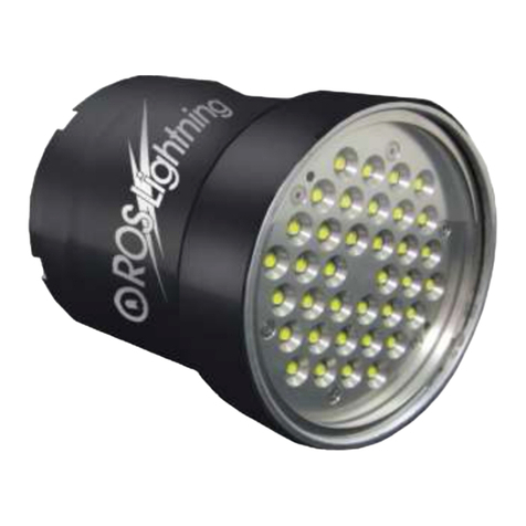
Ros L300 User manual

10-00972 REV A
II
TABLE OF CONTENTS
WARRANTY ..................................................................................................................III
CUSTOMER ASSISTANCE...........................................................................................IV
CHANGE RECORD........................................................................................................V
1WARNINGS.............................................................................................................1
2DESCRIPTION.........................................................................................................1
3PRODUCT SPECIFICATIONS ................................................................................2
4INSTALLATION.......................................................................................................3
5OPERATION............................................................................................................4
6MAINTENANCE.......................................................................................................4
7TROUBLESHOOTING.............................................................................................5
Table of Tables
Table 1, Specifications....................................................................................................2
Table 2, Trouble Shooting...............................................................................................6
Table of Figures
Figure 1, L300 Installation –Side Connector Configuration............................................3
Figure 2, L300 Installation –Back Connector Configuration ...........................................3

10-00972 REV A
III
WARRANTY
ROS, Inc. (hereinafter called "ROS") warrants its products as stated below subject to the
conditions specified.
ROS warrants its products, when operated under normal conditions, to be free from defects in
material or workmanship for a period of two years from the date of purchase provided that
inspection by ROS discloses that such defects developed under normal and proper use. ROS
products repaired or replaced pursuant to this warranty shall be warranted for the unexpired
portion of the warranty applying to the original product. The liability of ROS under this warranty
shall exist subject to the following conditions:
(a) Purchaser properly notifies ROS of such defects and the defective product is
returned to ROS, transportation charges paid by Purchaser.
(b) ROS shall be released from all obligations under its warranty in the event repairs
or modifications are made by persons not authorized by ROS.
(c) Representations and warranties made by any person, including distributors and
representatives of ROS, which are inconsistent or conflict with the terms of this
warranty, shall not be binding upon ROS unless reduced to writing and approved
by an officer of ROS. ROS shall in no event be liable for other direct, special,
incidental, consequential, indirect or penal damages.
(d) The laws of the State of California shall govern this warranty.
In the event the defect is determined to be within the terms of this warranty then ROS agrees to
repair and/or replace (at ROS' discretion) the product or defective portion at no charge to the
Purchaser. This warranty does not apply to expendable items or to normal wear-and-tear, and
is conditional upon performance of normal preventative maintenance procedures.
Our commitment to quality and customer service directs us to constantly strive to improve our
products. The materials and specifications presented in our manuals and data sheets are
correct and accurate to the best of our knowledge, and are presented in good faith. However,
the information is not guaranteed and is subject to change without notice.
LIMITATIONS OF REMEDIES
Purchaser assumes all risk and liability for results obtained in any installation, operation, or use
of the product. Purchaser’s sole remedy for any breach of warranty by vendor shall be limited to
the “express remedies” set forth above. Otherwise, in no event shall vendor, its agents, or
employees be liable to the original purchaser or any third party for any consequential or
incidental damages or expenses of any nature arising directly out of or in connection with the
use of vendor projects, even if vendor has been advised of the possibility of such damages or
expenses. In any event, unless otherwise contrary to state law, vendor liability under this limited
warranty shall not exceed the purchase price of the product.
10-00972 REV A
IV
CUSTOMER ASSISTANCE
ROS, Inc. uses a worldwide network of stocking distributors and representatives who
are familiar with our products and are able to provide assistance during installation
and/or operation of these products.
If you have any questions or problems with this product that are not covered by this
manual or instruction, please contact our agent in your area, or contact us directly by
phone or FAX or e-mail.
TEL: (001) 858-565-8500
FAX: (001) 858-565-8808
Web Site: www.rosys.com

10-00972 REV A
V
CHANGE RECORD
REV DESCRIPTION DATE
A PRODUCTION RELEASE (EC-02057) 23JUL14

10-00972 REV A
1
1 WARNINGS
WARNING: Assembly, disassembly, connecting cables, or
disconnection of cables, must only occur when the L300 light is
disconnected from the power source.
Please be cautious anytime you are dealing with the L300 underwater LED
lighting system. The light is extremely bright and looking directly at the light while
it is on could pose a health risk such as blindness. Protective eyewear is
required. ROS recommends Honeywell Uvex Stealth® OTG goggles with Shade
5.0.
When handling the L300 underwater LED lighting system, or any of its
components, please be aware that the light is relatively heavy. Dropping the
L300 could result in personal injury or damage to the light.
Be careful when handling the light and cables due to exposed male pins on the
connectors. The pins can be damaged if they are bumped excessively. Any
damage may result in difficulty when connecting cables or possible flooding for
those connections when underwater.
When handling the cables, do not pull or tug on the cables more than necessary.
Connector or cable damage through cutting of the jacket may result.
If operating the L300 in air, be aware that the housing can reach temperatures of
50°C hotter than the surrounding air. It may be too hot to comfortably touch the
L300 with your bare hand.
2 DESCRIPTION
The L300 is a revolutionary deep sea LED luminaire utilizing the most advanced
technology on the market. Unlike many other lights, the L300 does not use commercial
LED controllers. The L300 is a microprocessor based controller that was designed
specifically to meet the needs of customers using lights at extreme ocean depths. The
quality, uniform distribution, and intensity of the light from the L300 makes it the highest
performing light for the oceanographic community.
The L300 configuration options include RS-485 control and analog control with either 0-
to-5V or 0-to-10V control. Also available are flood or spot, side or reverse connector
mounting, and of course many different connectors.

10-00972 REV A
2
3 PRODUCT SPECIFICATIONS
Mechanical Light Head
Housing Material
Anodized Aluminum
Window Material
Optical Grade Polycarbonate
Mounting
2x 1/4-20 UNC-2B
Weight in Air
3.0 lb (1.4 kg)
Weight in Water
1.5 lb (0.6 kg)
Size
3.3in (84mm) x 5.1in (128mm) x 2.6 in
(66mm) excluding connectors
Environmental
Depth Rating
6000 MSW (19,685 ft)
Test Pressure
10,000 PSI
Min/Max Operating Temperature (in water)
-10°C to 40°C
Storage Temperature (in air)
-25°C to 80°C
Power Supply Thermal Protection
Thermal cutoff when power supply
reaches 80°C / resets at 60°C
Optical/Electrical
Color Temperature
6300 K (typical)
Color Rendering Index (CRI)
65
Light Output
5,000 lumens (typical)
Beam Pattern
Floodlight 90° (conical)
Spotlight 38° (conical)
End of Life Light Output
70% Rated Intensity at 30,000 Hrs
Input Voltage Range
18-30VDC
Current Draw
3.3A (typical)
Inrush Current
Less than 2 Amps for 100 ms after power
on
Table 1, Specifications

10-00972 REV A
3
4 INSTALLATION
Your new LED luminaire is intended for years of service free use. Please contact your
sales representative should any issues arise with your new luminaire.
Figure 1, L300 Installation –Side Connector Configuration
Figure 2, L300 Installation –Back Connector Configuration

10-00972 REV A
4
The L300 can be ordered in either a back connector or side connector configuration,
with many different connector options. Two ¼”-20 mounting holes are drilled and
tapped as shown in Figure 1, L300 Installation, to provide a convenient mounting point.
5 OPERATION
The L300 is designed for the ultimate simplicity of operation. First, connect +24VDC
power and return to the respective pins of the light. Enable power. For Analog
dimming, connect the dimmer’s analog dimming and signal ground to the respective
pins on the L300. The power to the light increases proportionally from 0V to max
analog dimming voltage. For RS485 dimming, connect the RS485A, RS485B, and
signal ground of the RS485 transceiver to the respective pins of the L300. Use the
command set provided by the ROS RS485 communication protocol, 21-30022, to
control the light.
CAUTION: It is important to remember that the L300 is designed to operate
underwater. As a minimum, the L300 should be completely submerged for
adequate cooling -- though it may be operated in air for short durations.
The L300 should not be removed from the water prior to the power being shut off.
Operating the L300 light in air may rapidly lead to an over temperature condition.
The L300 is designed with an active current limiting circuit for in-rush current. When
initially powered on, the L300 will draw less than 2 Amps for the first 100 milliseconds of
operation. After this period the current draw will depend upon the brightness level being
commanded.
6 MAINTENANCE
The L300 is intended to be maintenance free. Seals do not require periodic
replacement, but lubricant is applied on the external connectors and o-rings at the
factory. The L300 is purged with dry air to eliminate moisture which prevents problems
with corrosion and condensation.
Though the L300 is constructed of highly corrosion resistant materials, corrosion of all
components can further be minimized by ensuring a good earth ground on the power
input. Additionally, we recommend careful handling procedures be used to prevent
deep scratches or dents which can remove the anodize coating and create localized
corrosion.
In the event the L300 stops working, please contact ROS customer service. For
troubleshooting please see section 7.

10-00972 REV A
5
7 TROUBLESHOOTING
This section provides information on trouble shooting the L300.
Note: ROS does not recommend servicing the L300 in the field. If you discover a
failure or undesirable condition, then please contact ROS for return authorization.
The information presented in this section is designed to provide a guide for isolating the
source (root) of any problems that may be observed during the operation of the L300. If
a failure is noted the only option for repair in the field is to replace the failed item.
Failure modes, causes, and corrective action are listed in Table 2, Trouble Shooting.
WARNING: Assembly, disassembly, connection of cables, or disconnection
of cables, must only occur when the L300 is disconnected from the power
source. Debugging procedures with the L300 partially assembled and
powered on may only be executed by qualified personnel.
CAUTION: During operation the L300 can become hot to the touch. Care
must be taken to allow the system to cool down to ambient (room)
temperatures prior to handling.
WARNING: Avoid direct eye exposure from clear window. Near UV and
blue light can cause eye injury.
WARNING: Fault isolation procedures involve the measurement of
potentially dangerous voltages at possibly fatal current levels. These
procedures should only be executed by personnel that are qualified in such
procedures and who are authorized to undertake such procedures.
Prior to performing any fault isolation procedure, the system should be inspected for any
signs of visible damage. These may include denting, discoloration, corrosion, or
flooding. All connectors should be inspected to assure that pins are straight and no
damage has occurred that could allow misalignment or flooding.

10-00972 REV A
6
Problem
Typical Cause
Corrective Action
No light emitted from L300
Power not supplied
Disconnect the L300 system
from the mains. Test mains
power.
Reconnect the L300 as
appropriate.
Cable malfunction
Check or replace cables
Dimmer failure
Check or replace the dimmer
Seal failure
Check for water inside the
housing
Connector failure
Replace the L300
Driver board failure
Replace the L300
LED array failure
Replace the L300
Low light emitted from L300
Dimmer failure
Check or replace the dimmer
Driver board failure
Replace the L300
LED array failure (only
some LEDs are on)
Replace the L300
Aging of LED array.
Check specifications and
operation history. Replace
the L300.
L300 turns off while
powered
Over temperature
protection of Light Head
or Power Supply
Allow the L300 light to cool
for 30 minutes in air, or 15
minutes in water. The
temperature of the L300
should be 40°C or less when
power is reapplied.
DC Power Low Voltage
Evaluate power capacity of
power supply to verify L300
is not overloading.
L300 does not respond to
dimming command
Dimmer failure
Check or replace the dimmer
Driver board failure
Replace the L300
Table 2, Trouble Shooting
Table of contents
Other Ros Underwater Lighting manuals
Popular Underwater Lighting manuals by other brands

Poolexa
Poolexa Jandy Pro Series installation manual

Brilix
Brilix LED-P100 user guide

ASTEL
ASTEL MDU13 operating instructions

Astral Pool
Astral Pool LumiPlus RAPID Installation and maintenance manual

Astral Pool
Astral Pool LumiPlus PAR56 DC Installation and maintenance manual

hentech
hentech HT005C-P-T instruction manual

Oase
Oase ProfiLux LED 110 operating instructions

Aero
Aero 31201.030 installation instructions

emaux
emaux UL-P300 Series user manual

Lumascape
Lumascape LS5070 installation instructions

Filix
Filix ARPOOL IRIS TRIFECTA installation instructions

Platek
Platek MICRO STEEL REC 5.8W RGBW SPOT Assembly instructions