Hayward SP0512 Series User manual

IS0512 - REV B - 06
Caractéristiques techniques
300 W - 12 V - AC / Utiliser un transformateur de sécurité avec un secondaire > ou égal à 300 VA sous 12 V
Maintenance du produit
Le remplacement de pièces doit être effectué avec des pièces d’origines. Lors d’un changement d’ampoule et / ou du câble, il est préconisé de
changer la totalité des pièces assurant l’étanchéité. Type de lampe utilisé : PAR 56 en cas de nécessité de changement de la lampe, utiliser la pièce d’origine.
Notice de montage pour piscines panneaux / liner et piscines polyester
1. Faire la découpe dans le panneau selon les dimensions reprises sur la figure II
2. Passer la niche au travers du panneau. L'insert en métal vers le haut.
2a. Pour les piscines polyester (sans liner), mettre un cordon de silicone ou autre pâte d'étanchéité autour de l'arrière de la collerette.
3. Aligner les trous des 2 vis de fixation (supérieur et inférieur) de la niche et du panneau et engager les vis. Cette étape peut être éliminée en cas de
piscines polyester sans liner.
4. Aligner les trous de la couronne arrière et du panneau. Fixer la niche et la couronne arrière au panneau avec les 2 vis auto-taraudeuses 13 x 5/8".
4.a Pour les piscines polyester (sans liner), mettre un cordon d'étanchéité (silicone ou autre) sur la surface de la couronne arrière.
5. Aligner les trous du joint et de la niche et fixer le joint avec un peu de colle. (Les 2 trous plus larges dans le joint viendront au-dessus des 2 têtes de
vis auto-taraudeuses de fixation.)
6. En cas de piscines liner, procéder à l'installation du liner avant de passer au point 7.
7. Aligner le second joint (pas nécessaire pour les piscines polyester sans liner), et la face avant et fixer l'ensemble à la niche à l'aide des 10 vis autota
raudeuses N° 13 x 1 1/4". (S'assurer que les réserves prévues dans la face avant soient placées sur les têtes de vis de fixation). En cas de piscine
liner, percer le liner au travers des trous de la face avant d'engager les vis (un trou à la fois). Les vis passent au travers ; 1-Face avant ; 2-Joint ;
3-Liner ; 4-Joint ; 5-Niche ; 6-Panneau ; 7-Couronne arrière.
8. En cas de piscine liner, couper le liner le long de la partie inférieure de la face avant.
Notice de montage pour piscines panneaux bois / liner ou panneaux fibre / liner
1. Faire une découpe dans le panneau sur base de maximum 310 mm, minimum 303 mm dimension extérieure. (Environ 3 mm plus grand que la
dimension extérieure de la couronne arrière.)
2. Placer la couronne arrière dans la découpe par l'arrière du panneau et fixer à l'aide de 6 vis à bois de longueur adéquate (vis non fournies).
3. Passer la niche au travers du panneau par l'intérieur du bassin (insert en métal vers le haut).
4. Aligner les 2 trous de vis de fixation au-dessus et au-dessous de la niche et ceux de la couronne arrière et fixer l'ensemble par les 2 vis auto-tarau
deuses n° 13 x 5/8".
5. Aligner les trous des joints et ceux de la niche. Fixer le joint avec un peu de colle. (Les deux trous de plus large dimension se positionnent sur les 2
têtes de fixation.)
6. Installer le liner.
7. Aligner le deuxième joint et la face avant. Fixer l'ensemble à l'aide des 10 vis n° 13 x 1 1/4". Veiller à ce que les réserves prévues dans la face
avant soient bien placées sur les têtes des vis de fixation. Percer le liner au travers des trous de la face avant d'engager les vis.
8. Couper le liner le long de la partie intérieure de la face avant.
ATTENTION: En cas de piscine liner, ne pas oublier de positionner la couronne arrière SPX0507D avant de sceller la niche dans le béton.
HAYWARD POOL EUROPE
Parc Industriel de la plaine de l’Ain -
Allée des Chênes
01150 Saint-Vulbas - France
http://www.hayward.fr
PROJECTEUR INCANDESCENCE - Série SP0512xxxx
INCANDESCENT UNDERWATER LIGHT - Serial SP0512xxxx
PROYECTOR INCANDESCENTE : Serie SP0512xxxx
UNTERWASSER SCHEINWERFER - Serie SP0512xxxx
FIG I
SPX0512A
Face avant
Front ring
Frontring
Cara anterior
PR20005
Ampoule
Bulb
Birne
Lampara
SPX0540Z16E
Vis de fixation
Lock screw
Halterungsschraube
Tornillo de fijacion
SPX0512CKIT
Presse étoupe
Conduit connector
Stopfbüsche
Prensa estopa
SPX0508A (Liner, Vinyl)
SPX0556 (Béton, Concrete)
Niche, Niche
Einbaunische, Nicho
SPX0555Z2
SPX1088M
SPX0512Z1
Joint torique
O-ring
O-ring
Junta torica
SPX0512B
Support
Lamp bracket
Gehäuse
Soporte

Procédure en cas de remplacement du liner
Dévisser la vis supérieure de fixation (SP0540Z16E) de l'optique et sortir le bloc de son logement. Dévisser les 3 vis (SP1088M).
Remettre le tripode, l'ampoule et son joint dans la niche. Dévisser les vis de fixation (SP1030Z1) de la couronne d'étanchéité (SP0507A1). Changer
le liner. Refixer la couronne SP0507A1. Refixer le tripode à l'aide des 3 vis SP1088M. Remettre le bloc optique en place. Refixer la vis supérieure
SP0540Z16E.
Installation du projecteur
Passer le câble d'alimentation dans le presse-étoupe de la niche et le tirer jusqu'à la boîte de jonction. NE PAS COUPER L'EXCEDENT DE CABLE.
Cet excédent est nécessaire pour pouvoir sortir l'ampoule du bassin lorsqu'il faut la remplacer.
Laisser assez de câble pour pouvoir atteindre la margelle et éventuellement couper l'excédent à ce moment seulement.
Enrouler le câble autour du tripode de fixation de l'ampoule et placer l'ensemble dans la niche en prenant soin de garder la vis de fixation à 12 heures.
Glisser la vis de retenue située au bas de la niche dans le logement prévu sur la face avant et s'assurer de son bon engagement. Fixer l'ensemble en
vissant la vis supérieure dans son logement. Pour enlever le projecteur de la niche, dévisser la vis supérieure, lever et sortir le projecteur.
Raccordement dans la boîte de connexion (non fournie)
Préconisation de raccordement : raccorder dans la boite de connexion (non fournie) IPX5, l’extrémité du câble à l’alimentation venant du local tech-
nique,utiliser les blocs de jonctions fournis avec les boites de connexion pour raccorder le projecteur à l’alimentation en torsadant les fils et serrant bien
les vis des bornes de jonctions.
Technical characteristics
300 W - 12 V - AC / Use a safety transformer with an output greater than or equal to 300VA at 12 V
Product maintenance
Original components must be used in all replacement operations. When changing a bulb and/or cable, it is recommended that all components be
changed to avoid compromising the seals.Type of light used : PAR 56, in the event of necessity changing of the light, to use original part.
Installation instructions for vinyl liner pools with metal or fiberglass panels ; and fiberglass pools
1. Drill and cut out wall panel section per dimensions on drawing II, if not pre-punched by factory.
2. Insert niche through panel section from interior of pool. Brass insert at TOP (12 o' clock).
2a. For fiberglass pools (without liner) : Caulk rear side of niche flange with silicone or other suitable sealing compound prior to inserting niche through
pool wall.
3. Align the two securing screw holes (at top and bottom) of the niche with those of the wall panel and insert the two pan head securing screws through
niche and panel. This step may be eliminated for fiberglass pools (without liner).
4. Align the holes of the backup rim with those on the exterior side of the wall panel and fasten the niche and backup rim to the wall panel with the two
N° 13 x 5/8" self-tapping pan head securing screws.
4a. For fiberglass pools (without liner) : Caulk front surface of backup rim prior to installing.
5. Align holes in gasket with holes in niche and affix to niche with small quantity of adhesive cement to hold gasket in place (Two large holes in gasket
will fit over the pan heads of the securing screws.)
6. If vinyl liner pool, install liner before proceeding with Step 7.
7. Align second gasket, (not required for fiberglass pools without liner), and face plate and fasten tightly to niche assembly with ten (10) N° 13 x 1 1/4''
flat head self-tapping screws provided. Use a large Phillips screwdriver for these heavy duty screws. (Note : make sure that the two countersinks on
the back of face plate line up with the heads of the two securing screws.) If vinyl liner pool, pierce liner through face plate holes one at a time prior to
inserting screws. Screws secure through : 1-Face plate ; 2-Gasket ; 3-Liner ; 4-Gasket ; 5-Niche ; 6-Panel ; 7-Into back-up ring.
8. If vinyl liner pool, cut out liner along inside edges of face plate. Follow pool manufacturer's instructions.
Installation instructions for wood or fibre panel vinyl pools
1. Cut out wall panel to 12-3/8" maximum, 12-1/8" minimum O.D. (Approximately 1/8" larger than O.D. of backup ring).
2. Insert backup ring through circular hole, from rear of panel, and fasten to rear of panel with (6) brass wood screws of proper length (not furnished).
3. Insert niche through panel from interior of pool. Brass insect at TOP (12 o'clock).
4. Align the two securing screw holes at top and bottom of the niche with those of the backup ring and secure the niche to the backup ring with two (2)
N° 13 x 5/8" self-tapping pan head securing screws.
5. Align holes in gasket with holes in niche and affix to niche with small quantity of adhesive cement. (Two large holes in gasket will fit over the pan heads
of the securing screws).
6. Install vinyl liner.
7. Align second gasket and face plate and fasten tightly to niche assembly with ten (10) N°. 13 x 1 1/4" flat head self-tapping screws provided. Use a large
size Philips screwdriver for these heavy duty screws. (Note : Make sure that the two countersinks on the back of face plate line up with the heads of
the two securing screws.) Pierce liner through face plate holes one at a time prior to inserting screws.
8. Cut out liner along inside edges of face plate.
ATTENTION: For a liner swimming pool, do not forget to position the rear ring SPX0507D before cementing the niche into the concrete.
Changing the pool liner
Unscrew the face rim lock screw (SP0540Z16E). Take out SP512 light unit. Unscrew 3 SP1088M screws releasing the SP0512A front rim. Keep the
SP0512A aside and leave the other components in the niche.
Unscrew the SP1030Z1 screws releasing the face plate SP0507A1. Change the liner. Screw SP0507A1 back in place not to forget the installation of
the gasket SP506DE. Screw the bulb tripod back on the SP0512A front rim. Coil the cable around the light fixture and screw the unit back in the niche.
Light installation
Snake the 2-conductor electric cords through the conduit outlet of the fixture housing (niche), into the conduit, and up to the junction box. DOT NOT CUT
EXCESS CORD. The extra footage of cord is provided to allow for raising the fixture to the pool deck for re-lamping. Leave sufficient cord to reach from
fixture housing to deck. (After allowing for re-lamping and length of run footage, cut off any extra, unneeded cord.)
TO INSTALL LIGHT FIXTURE. Coil the extra electric cord around the lighting fixture and place the fixture into the niche, which face rim lockscrew at top
(12 o'clock). Slide/place the notch at bottom (6 o'clock) of the face rim down over the bolt head at the lower edge of the niche. Be sure it catches. Secure
the fixture at the top by screwing in the lockscrew. When removing fixture from niche, unscrew the lockscrew at top of fixture and lift fixture up and out
of the niche.
NOTE : Wiring, splicing and grounding within the junction box should be performed only by a licensed electrician.
Connection within the junction box (not available)
Recommendation of connection : to connect in the junction box (not available) IP X 5, the end of the cable for electrical power supply coming from the
technical box,Use the connector blocks provided with the junction box to connect the spotlight to the power supply by twisting the wires and ensuring
that th terminal screws are well tightened.

Metal or fiberglass cut-out
- Cut out 272 m/m MAX.
270 m/m MIN.
- Drill 10 holes 5/16" spaced 36°
on 11 1/2 B.C.
- Drill 2 holes 1/4" spaced 180°
on 11 1/2" B.C.
Découpe pour panneaux acier ou
libre
- Découpe circulaire de 272 m/m
MAX. et 270 m/m MIN.
- Forer ou percer 10 trous de 5/16"
espacés de 36° et inscrits dans
un cercle de 287,5 m/m.
- Forer ou percer 2 trous de 1/4"
espacés de 180°
Ausschnitt für Metal oder
Glasfaserwand
- Runder ausschnitt max 272 m/m
MAX. - 270 m/m MIN..
- 10 Löcher 5/16" - 36°
Zwischenraum und eingefügt in
einem Kreis von 287,5 m/m
- 2 Löcher 1/4" - 180°
Zwischenraum
Recorte para panel en acero o fibra :
- circular de 272 m/m MAX.
y 270 m/m MIN.
- Hacer 10 agujeros de 5/16" espa
cios 36° e inscritos en un circulo
de 287,5 m/m.
- Hacer 2 agujeros de 1/4" espa
cios de 180°
Technische Daten
300 W - 12 v - AC / Einen Sicherheitstransformator mit einer Sekundärwicklung 300 VA / 12 V oder entsprechend benutzen.
Produktinstandhaltung
Zum Austauschen Originalteile benutzen. Beim Wechsel einer Glühbirne und/oder des Kabels wird das Austauschen aller Dichtungsteile empfohlen.
Benutzter lampentyp: PAR 56 bei der lampe das ursprungsstück zu benutzen.
Montage bei vorgefertigten Becken mit Folienauskleidung und Polyester Becken
1. Ein Loch in die Beckenwand bohren, laut Abmessungen auf Zeichnung II.
2. Nische, mit Metall-Gewindebüchse nach oben, durch das Loch in der Wand führen.
2a. Bei Polyesterbecken (ohne Folie) muß um den Nischenkragen herum mit etwas Silikon (oder ähnlichem Dichtungsmaterial) abgedichtet werden.
3. Die 2 Befestigungslöcher (oben und unten) der Nische mit den in der Beckenwand gebohrten Löcher ausrichten. Nicht notwendig bei
Polyesterbecken ohne Folie.
4. Die Löcher des Gegenflansches mit denen der Beckenwand ausrichten. Nische und Gegenflansch mit 2 selbstschneiden Schrauben (13 x 5/8") an
die Wand befestigen.
4a. Bei Polyesterbecken ohne Folie muß um den Gegenflansch herum mit etwas Silikon (oder ähnlichem Dichtungsmaterial) abgedichtet werden.
5. Die Löcher der Kortendichtung mit denen der Nischen ausrichten und Dichtung mit etwas Kleber auf die Nische fixieren.
(Die 2 größeren Löcher der Dichtung müssen über 2 selbstschneidende Befestigungsschrauben gelegt werden.)
6. Bei Becken mit Folienauskleidung muß jetzt die Folie angebracht werden.
7. Den 2 Dichtungsring (nicht notwendig bei Polyesterbecken ohne Folie) mit der Blende ausrichten und das Ganze mit Hilfe von 10 selbstschneiden
den Schrauben (13 x 1 1/4") auf die Nische befestigen. (Dafür Sorge tragen, dass die 2 runden Aussparungen in die Rückseite der Blende über den
2 Befestigungsschrauben passen. Bei Folienbecken müssen bevor die Blende mit den Schrauben befestigt wird, durch die Blende hindurch Löcher
in die Folie gebohrt werden. (Loch für Loch bohren und befestigen.) Die Schrauben durchdringen : 1-Blende ; 2-Dichtung ; 3-Folie ; 4-Dichtung ; 5
Nische ; 6-Wand ; 7-Gegenflansch.
8. Bei Folienbecken muß die Folie dann noch der Innenseite der Blende entlang weggeschnitten werden.
Montage bei Elementbaubecken aus Holz oder Kunststoff mit Folienauskleidung
1. Ausschnitt im Wandsegment machen. Aussenabmessung max. 310 m/m, minimal 303 m/m/ (Ungefähr 3 m/m größer als das Aussenmaß des
Gegenflansches.)
2. Gegenflansch mittels 6 Holzschrauben an die Rückseite an die Rückseite der Wand befestigen (Holzschrauben in der Lieferung nicht einbegriffen).
3. Nische, mit Metall-Gewindebüschse nach oben, von Innen nach aussen durch den Wandausschnitt führen.
4. Die 2 Befestigungslöcher (oben und unten) der Nische mit denen des Gegenflansches ausrichten und das Ganze mit 2 selbstschneidenden
Schrauben Nr 13 x 5/8" befestigen.
FIG II
270 mm MAX
320 mm O.D.
2 Trous rspaces de 180°
2 Holes spaced 180°
2 Löcher auf 180°
2 Orificios espaciados 180°
“TOP”
SPX0507Z1A
10 vis auto-taraudeuses
10 screws n°13x1 1/4”
10 Selbstschneidende schrauben
10 Tornillos autotaladrantes
Liner
Vinyl
Folie
Liner
Piscine bois
Wood panel
Holz wand
Madera SPX0512CKIT
Presse étoupe
Conduit connector
Stopfbüchse
Prensa estopa
SPX0506DE
Joints
Gaskets
Dichtungen
Juntas
10 Trous rspaces de 36°
10 Holes spaced 36°
10 Löcher auf 36°
10 Orificios espaciados 36°
SPX1411Z1A
2 vis auto-taraudeuses
2 screws n°13x 5/8”
2 Selbstschneidende schrauben
2 Tornillos autotaladrantes Panneau acier
Metal panel
Metal wand
Panel aluminio
SPX0507D
Couronne arrière
A fixer avant de sceller
Back up ring
To fix befor sealing
Gegenflansch
Zubefestigen, befor zu
versiegeln
Corona trasera
A fijar antes de sellar

5. Die Löcher der Dichtung mit denen der Nische ausrichten und mit etwas Kleber auf der Nische fixieren
(Die 2 grösseren Löcher der Dichtung müssen über die 2 Befestigungsschrauben gelegt werden).
6. Folie anbringen.
7. Den 2. Dichtungsring mit der Blende ausrichten. Das Ganze mit 10 Schrauben Nr 13 x 1 1/4" auf der Nische befestigen.
(Die 2 runde Aussparungen in der Rückseite der Blende müssen über die 2 Befestigungsschrauben passen. Bevor die Blende mit den Schrauben
befestigt wird, müssen aber erst durch die Blende hindurch Löcher in die Folie gemacht werden.)
8. Die Folie der Innenseite der Blende entlang wegschneiden.
ACHTUNG: Bei einem Liner-Schwimmbecken nicht vergessen, die hintere Krone SPX0507D zu positionieren, bevor die Nische im Beton versiegelt wird.
Verfahrensweise beim Folienwechsel
Obere Halterungschraube (SP0540Z16E) lösen und Scheinwerfer aus seinem Sitz herausnehmen. Drei Schrauben (SP1088M) lösen und Glühbirne
mit Halterung und Dichtung in die Nische zurück legen.
Befestigungschrauben (SP1030Z1) aus dem Flanschrahmen (SP0507A1) losschrauben. Folie auswechseln. Flanschrahmen SP0507A1 wieder
festschrauben. Glühbirne anhand der drei Schrauben SP1088M wieder an ihre Halterung befestigen. Scheinwerfer in seinen Sitz zurückbringen und
Halterungsschraube SP0540Z16E anziehen. Montage der lampe
Den Kabel durch die Stopfbüchse der Einbaunische führen und bis zur Verteilerdose ziehen. ÜBERFLÜSSIGEN KABEL NOCH NICHT ABSCHNEIDEN
da dieser dazu dient um beim eventuellen Auswechseln der Birne den Scheinwerfereinsatz aus der Nische zu entfernen und auf den Beckenrand zu
legen. Nur wenn dies möglich ist darf der Kabel gegebenenfalls gekürzt werden.
Den kabel um das Scheinwerfergehäuse wickeln und den Einsatz in die Nische setzen. Die Befestigungsschraube des Frontrings muss sich dabei
oben befinden. Die Stellschraube in unterem Bereich der Nische in die dafür vorgesehene Öffnung des Frontrings gleiten und den Einsatz jetzt defini
tiv mit der oberen Befestigungsschraube festdrehen. Um den Einsatz aus der Nische zu entfernen lösen Sie die obere Befestigungsschraube und
heben Sie den Einsatz aus der unteren Stellschraube.
ANSCHLIESSEN IM KABELVERBINDUNGSKASTEN
(nicht geliefert)
Verbindungspräkonisation : zu verbinden in hinkt es von Verbindung (nicht geliefert) IPX5, extremite vom kabel an der Ernährung, das vom technis-
chen raum kommt. Zum Anschließendes Scheinwerfers an die Stromversorgung die mit dem Anschlusskasten gelieferten Reihenklemmen benutzen,
wobei die Drähte verdrillt und die Schrauben der Lütsterklemmen gut festgezogen werden.
Caracteristicas tecnicas
300 W - 12 V - AC / Utilizar un transformador de seguridad con un secundario > o igual a 300 VA y 12 V. Presentar el òptico antes del nicho enrollan-
do del cable. Mantenimiento del producto
El reemplazo de las piezas se debe efectuar con piezas originales.
Al cambiar un abombilla y/o un cable, se aconseja cambiar la totalidad de las piezas que aseguran la estanqueidad. Tipo de làmpara utilizado : PAR
56. En caso de necesidad de cambio de la làmpara, utilizar la parte de origen.
Instrucciones de montaje (Piscinas Liner/Polyester)
1. Realizar el recorte en el panel de aluminio según las dimensiones indicadas en el dibujo.
2. Pásar el nicho a través del panel. El pasacables del nicho debe de quedar hacia arriba.
2a. Para las piscinas Polyester (sin liner), poner un cordón de silicona ó cualquier pasta similar por detrás de la lampara.
3. Alinear los orificios de los 2 tornillos de fijación (superior e inferior) del nicho y del panel de aluminio y apuntar los tornillos.
4. Alinear los orificios de la corona trasera y del panel de Aluminio. Fijar el nicho y la corona trasera al panel de aluminio con los 2 tornillos autotaladran
tes de 13 x 5/8".
4a. Para las piscinas Polyester (sin liner), colocar un cordón de estangueidad (silicona o similar) sobre la superficie de la corona trasera.
5. Alinear los orificios de la primera junta y del nicho y fijar la junta con un poco de pegamento (los 2 orificios más anchos en la junta se situarán enci
ma de las dos cabezas de los tornillos autotaladrantes de fijación).
6. Proceder a la instalación del liner, antes de pasar al punto.
7. Alinear la segunda junta con la cara delantera y fijar el conjunto al nicho con la ayuda de los 10 tornillos autotaladrantes N° 13 x 1 1/4" (asegurarse
que las reservas previstas en la cara delantera están situada sobre las cabezas de los tornillos de fijación. Perforar el liner a través de los orificios de
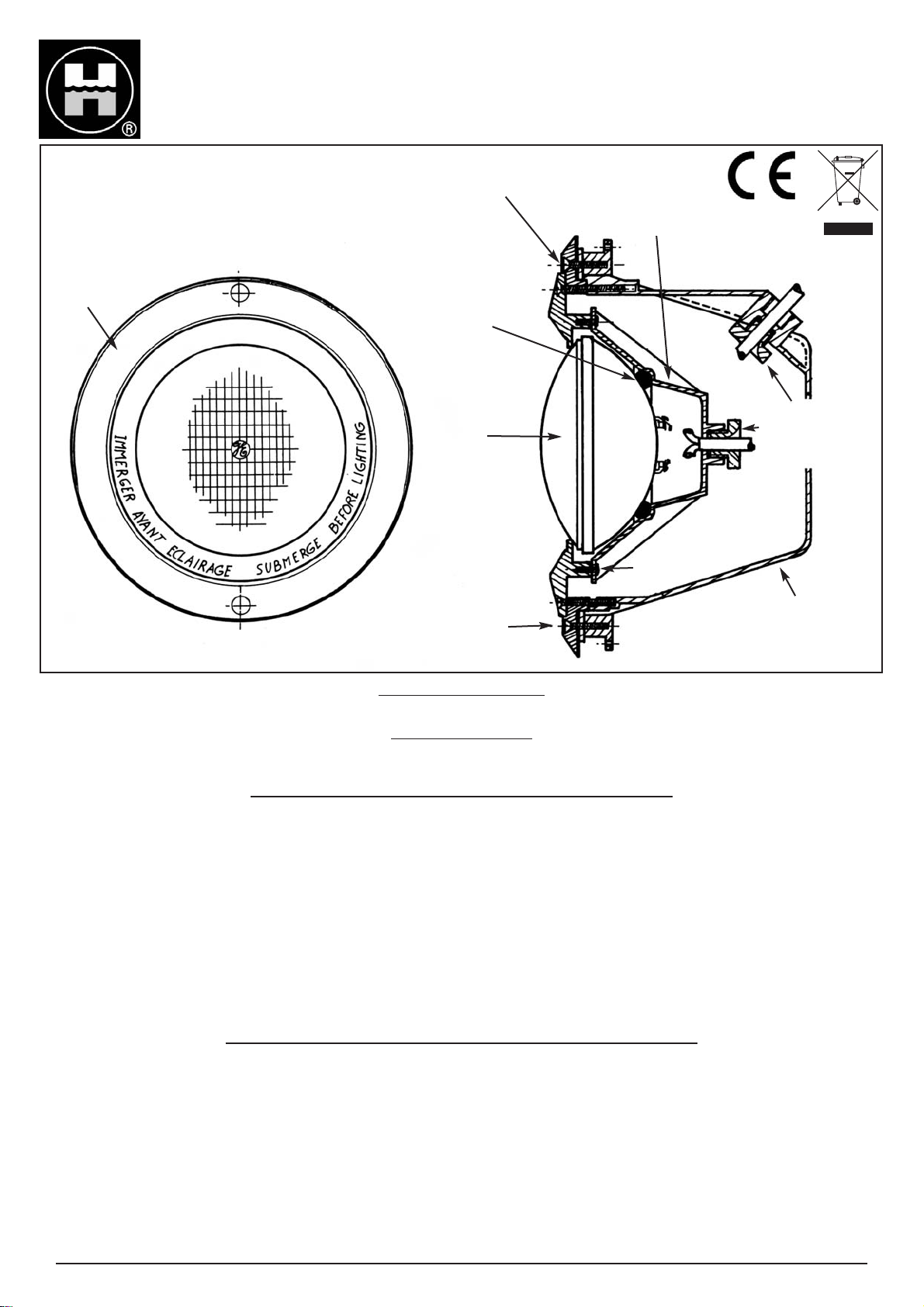
la cara delantera antes de apuntar los tornillos (un solo agujero a la vez). Los tornillos pasan a través de : 1- Cara delantera; 2- Junta; 3- Liner; 4-
Junta; 5- Nicho; 6- Panel de Aluminio; 7- Corona trasera.
8. Recortar el Liner por la parte interior de la cara delantera.
Instrucciones de montaje (Piscinas madera / liner - fibra / liner)
1. Realizar el recorte en el panel de aluminio según las dimensiones indicadas en el dibujo.
2. Pasar el nicho a través del panel. El pasacables del nicho debe de quedar hacia arriba.
3. Alinear los orificios de los 2 tornillos de fijación (superior e inferior) del nicho y del panel de aluminio y apuntar los tornillos.
4. Alinear los orificios de la corona trasera y del panel de Aluminio. Fijar el nicho y la corona trasera al panel de aluminio con los 2 tornillos autotaladran
tes de 13 x 5/8".
5. Alinear los orificios de la primera junta y del nicho y fijar la junta con un poco de pegamento (los 2 orificios más anchos en la junta se situaran enci
ma de las dos cabezas de los tornillos autotaladrantes de fijación).
6. Proceder a la instalación del liner, antes de pasar al punto.
7. Alinear la segunda junta con la cara delantera y fijar el conjunto al nicho con la ayuda de los 10 tornillos autotaladrantes N° 13 x 1 1/4" asegurarse
que las reservas previstas en la cara delantera están situadas sobre las cabezas de los tornillos de fijación. Perforar el liner a través de los orificios
de la cara delantera antes de apuntar los tornillos (un solo agujero a la vez). Log tornillos pasan a través de : 1- Cara delantera; 2- Junta; 3- Liner; 4-
Junta; 5- Nicho; 6- Panel de Aluminio; 7- Corona trasera.
8. Recortar el liner por la parte interior de la cara delantera.
ATENCIÓN: En caso de piscina liner, no se olvide de colocar la corona posterior SPX0507D antes de sellar el habitáculo en el hormigón.
Procedimiento en caso de sustitución del liner
Desatornillar el tornillo superior de fijación (SP0540Z16E) del óptico y sacar la lampara de su sitio. Desatornillar los 3 tornillos (SP1088M). Dejar el
trípode, la lampara y su junta en el nicho. Desatornillar los tornillos de fijación (SP1030Z1) de la corona de estanqueidad (SP0507A1). Cambiar el
liner. Volver a fijar la corona SP0507A1. Igualmente el trípode con la ayuda de 3 tornillos SP1088M. Voler a poner el conjunto óptico en su sitio. Volver
a fijar el tornillo superior SP0540Z16E. Instrucciones de montaje
- Pasar el cable de alimentación por el prensa-estopa del nicho y conducirlo hasta la caja de conexiones. NO CORTAR EL EXCEDENTE DE CABLE.
Este excedente es necesario para poder sacar la lámpara de la piscina para reemplazarla. Dejar suficiente cable para poder llegar a la albardilla y cor
tar eventualmente el excedente solo en ese momento.
- Enrollar el cable alrededor del tripode de fijación de la lámpara y ubicar el conjunto en el habitáculo previsto en la cara delantera, asegurandose de su
correcto emplazamiento. Fijar el conjunto con el tornillo superior. Para sacar el proyector del nicho, aflojar y quitar el tornillo superior y retirar el pro
yector. Conexion en la caja de conexion (no proporcionado)
Recomendaciòn de conexiòn : conectar en la caja de connexion ( no proporcionado) IP X 5, l’extremidad del cable a la alimentaciòn que viene del local
tècnico. Utilizar los bloques de uniones suministrados con las cajas de conexiòn para conectar el proyector a la alimentaciòn, torciendo los cables y
apretando boen los tornillos de los bornes de uniòn.
Table of contents
Languages:
Other Hayward Underwater Lighting manuals

Hayward
Hayward ColorLogic SP0536AF User manual

Hayward
Hayward UCL Niches User manual

Hayward
Hayward Proseries SP9120 User manual

Hayward
Hayward 7016849 User manual

Hayward
Hayward Universal ColorLogic User manual

Hayward
Hayward UCL Niches User manual

Hayward
Hayward ColorLogic® 4.0 User manual

Hayward
Hayward Universal ColorLogic User manual
Popular Underwater Lighting manuals by other brands

Underwater Lights USA
Underwater Lights USA Sea Vision SV16 Maintenance and care

Pond Boss
Pond Boss LRING3 manual

Oase
Oase LunAqua 10 LED operating instructions

PUK
PUK HYDRODIVE MINI Assembly and operating instructions

Messner
Messner UWL 12100 operating instructions

DeepSea Power & Light
DeepSea Power & Light LED Multi SeaCam Operator's manual