manuals.online logo
Brands
  1. Home
  2. •
  3. Brands
  4. •
  5. Rosemount
  6. •
  7. Measuring Instrument
  8. •
  9. Rosemount 1151 User manual

Rosemount 1151 User manual

LCD Meter
Product Manual
Right Configuration ButtonLeft Configuration Button
Analog
Bar Graph
00809-0100-4691
English
Rev. AA
INTRODUCTION
The Rosemount®LCD meter is designed to be used
with the Rosemount Model 1151 Smart and Analog Pressure
Transmitters, the Model 1144 Pressure Transmitter, the
Model 751 Field Signal Indicator, the Model 444 Temperature
Transmitter, and the Model 1135 Pressure-to-Current Converter.
The LCD meter plugs directly into these instruments to provide
an accurate digital display of the process variable. This manual
explains the configuration and assembly of the LCD meter and
includes applicable functional, performance, and physical
specifications.
This meter adds no voltage drop in the 4–20 mA current loop
when connected directly across the transmitter test terminals.
When used in the Model 751 Remote Signal Indicator, the meter
plugs into terminals 1 and 2.
LCD METER ASSEMBLY
Figure 1 shows the mounting hardware required to properly
install the LCD meter on a transmitter or in the field signal
indicator. This mounting hardware may also be used with the
Rosemount universal (analog) meter.
LCD METER CONFIGURATION
The LCD meter may be configured to meet specific
requirements by using the left and right configuration buttons
located on the meter face as shown on the cover. The analog bar
graph is also shown on the cover. The 20-segment bar graph is
factory calibrated and represents 4–20 mA directly.
No calibration equipment is required to configure the LCD
meter, but between 4 and 20 mA must be flowing through the
loop. The actual value of the current is not significant. In addition,
meter configuration does not affect the transmitter/loop current.
Use the following meter configuration procedure to properly
configure the LCD meter.
NOTE
The LCD meter time-out is approximately 16 seconds. If keys are
not pressed within this period, the indicator reverts to reading the
current signal.
Remove the cover
1. Unscrew the retaining ring shown onthe cover and lift the
transparent cover off of the housing.
Position the decimal point and select the meter function
2. Press the left and right configuration buttons
simultaneously and release them immediately.
3. To move the decimal point to the desired location, press
the left configuration button. Note that the decimal point
wraps around.
4. To scroll through the mode options, press the right
configuration button repeatedly until the desired mode
is displayed. See Table 1.
Store the information
5. Press both configuration buttons simultaneously for two
seconds. Note that the meter displays “----” for
approximately 7.5 seconds while the information is being
stored.
Set the display equivalent to a 4 mA signal
6. Press the left button for two seconds.
7. To decrease the display numbers, press the left
configuration button and to increase the numbers,
press the right configuration button. Set the numbers
between –999 and 1000.
8. To store the information, press both configuration buttons
simultaneously for two seconds. Note that the meter
displays “----” for approximately 7.5 seconds while the
information is being stored.
Set the display equivalent to a 20 mA signal
9. Press the right button for two seconds.
10. To decrease the display numbers, press the left
configuration button on the display and to increase the
numbers, press the right configuration button. Set the
numbers between –999 and 9999. The sum of the 4 mA
point and the span must not exceed 9999.
11. To store the information, press both configuration buttons
simultaneously for two seconds. Note that the meter
displays “----” for approximately 7.5 seconds while the
information is being stored. The LCD meter is now
configured.
Replace the cover
12. Make sure the rubber gasket is seated properly, replace
the transparent cover, and replace the retaining ring
.TABLE 1. LCD Meter Modes.
Options Relationship between Input Signal
and Digital Display
L in
L inF
Srt
SrtF
Linear
Linear with five-second filter
Square root
Square root with five-second filter
Square root function only relates to the digital display.
The bar graph output remains linear with the current signal.
Square root response
The digital display is proportional to the square root of the input
current where 4 mA = 0 and 20 mA = 1.0, scaled per the
calibration procedure. The transition point from linear to square
root is at 25% of full scale flow.
Filter response operates upon “present input” and “input
received in the previous five second interval” in the following
manner:
Display = (0.75 3previous input) + (0.25 3present input).
This relationship is maintained provided that the previous
reading minus the present reading is less than 25% of full scale.
LCD METER SPECIFICATIONS
Input Signal
4–20 mA dc.
Meter Indication
4-digit LCD showing –999 to 9999. A 20-segment bar graph
directly represents the 4–20 mA current.
Digital Display Resolution
0.05% of range ±1 digit.
Analog Bar Graph Resolution
1 mA or 5% of input range.
Indication Accuracy
0.25% of range ±1 digit.
Scaling/Configuration
4 mA Point Limits: –999 to 1000.
Span limits: 0200 to 9999.
The sum of the 4 mA point and span must not exceed 9999.
Adjustments are made using non-interactive zero and span
buttons.
Temperature Limits
Storage: –40 to 85 °C (–40 to 185 °F).
Operating: –20 to 70 °C (–4 to 158 °F).
Between temperatures –40 to –20 °C (–40 to –4 °F),
the loop is intact and the meter is not damaged.
Temperature Effect
0.01% of range per °C on zero.
0.02% of range per °C on span
Stability
Over Time: 0.1% of range ±1 digit for 6 months.
Overload Limitation
666 mA.
Update Period
750 ms.
Response Time
Responds to changes in input within a maximum of two update
periods. If the filter is activated, then the display responds to the
change within nine update periods.
Humidity Limitation
0 to 95% non-condensing relative humidity.
Power Interrupt
All configuration and calibration constantsare stored in EEPROM
memory and are not affected by power loss.
Failure Mode
LCD meter failure will not affect transmitter operation.
Under/Over Range Indication
Input current < 3.5 mA: Display blank.
Input current > 22.0 mA: Display flashes 112.5% of full scale
value or 9999, whichever is less.
Hazardous Locations
Approved for use with Rosemount Models 444, 751, 1135, 1144,
and 1151.
Meter Size
21/4-inch diameter face with 1/2-inch high characters.
Rosemount Inc.
8200 Market Boulevard
Chanhassen, MN 55317 USA
Tel 1-800-999-9307
Telex 4310012
Fax (612) 949-7001
P
R
I
N
T
E
D
IN
U.
S.
A.
© Rosemount Inc. 1997.
All rights reserved.
http://www.rosemount.com
¢00809-0100-4691S¤
00809-0100-4691, Rev. AA
Mounting Screw into
Mounting Plate
Mounting Screw
into Housing
Strap Washer
Retaining Straps
Mounting Screws
Terminal Screws
(Mount into Transmitter
“Test” Terminal Block)
Mounting Plate
Meter (Meter May Be
Rotated in 90° Increments)
Cover Bushing
Cover Foam Spacer
FIGURE 1. LCD Meter Exploded View.
751-0264B

Other Rosemount Measuring Instrument manuals
Rosemount 8712D Series User manual

Rosemount

Rosemount 8712D Series User manual

Rosemount 3051SFC_A User manual

Rosemount

Rosemount 3051SFC_A User manual

Rosemount 5402 User manual

Rosemount

Rosemount 5402 User manual

Rosemount FCL User manual

Rosemount

Rosemount FCL User manual

Rosemount 702 User manual

Rosemount

Rosemount 702 User manual

Rosemount 3300 Series Configuration guide

Rosemount

Rosemount 3300 Series Configuration guide

Rosemount 7D User manual

Rosemount

Rosemount 7D User manual

Rosemount 1195 User manual

Rosemount

Rosemount 1195 User manual

Rosemount 2081 pH User manual

Rosemount

Rosemount 2081 pH User manual

Rosemount P300 User manual

Rosemount

Rosemount P300 User manual

Rosemount 3308 Series User manual

Rosemount

Rosemount 3308 Series User manual

Rosemount 8750WA User manual

Rosemount

Rosemount 8750WA User manual

Rosemount TankRadar Pro Parts list manual

Rosemount

Rosemount TankRadar Pro Parts list manual

Rosemount 8732C User manual

Rosemount

Rosemount 8732C User manual

Rosemount 5081-P User manual

Rosemount

Rosemount 5081-P User manual

Rosemount Series 8700 User manual

Rosemount

Rosemount Series 8700 User manual

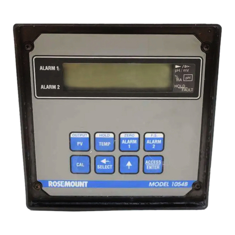
Rosemount 1054B User manual

Rosemount

Rosemount 1054B User manual

Rosemount 8714D User manual

Rosemount

Rosemount 8714D User manual

Rosemount P330 User manual

Rosemount

Rosemount P330 User manual
Rosemount TankRadar Rex 3900 Series User guide

Rosemount

Rosemount TankRadar Rex 3900 Series User guide

Rosemount 951C User manual

Rosemount

Rosemount 951C User manual

Rosemount Wireless Pressure Gauge User manual

Rosemount

Rosemount Wireless Pressure Gauge User manual

Rosemount 2120 User manual

Rosemount

Rosemount 2120 User manual

Rosemount 8712E User manual

Rosemount

Rosemount 8712E User manual

Popular Measuring Instrument manuals by other brands

Agilent Technologies 1145A User's and service guide

Agilent Technologies

Agilent Technologies 1145A User's and service guide

Mobeye ThermoGuard TwinLog CML2255 user manual

Mobeye

Mobeye ThermoGuard TwinLog CML2255 user manual

Schwarzkopf SALON LAB manual

Schwarzkopf

Schwarzkopf SALON LAB manual

Milwaukee MI455 instruction manual

Milwaukee

Milwaukee MI455 instruction manual

Ecom EN2 operating instructions

Ecom

Ecom EN2 operating instructions

Union Instruments INCA4003 Translation of the original operating instructions

Union Instruments

Union Instruments INCA4003 Translation of the original operating instructions

Dillenger KT-LCD3 user manual

Dillenger

Dillenger KT-LCD3 user manual

Panasonic DMRE20 - DVD VIDEO RECORDER operating instructions

Panasonic

Panasonic DMRE20 - DVD VIDEO RECORDER operating instructions

socomec COUNTIS E45 instruction manual

socomec

socomec COUNTIS E45 instruction manual

Southwire 23090T MaintenancePRO operating instructions

Southwire

Southwire 23090T MaintenancePRO operating instructions

Relat BM3000 user manual

Relat

Relat BM3000 user manual

ThermoWorks ThermaQ 2 operating instructions

ThermoWorks

ThermoWorks ThermaQ 2 operating instructions

Landis+Gyr ULTRAHEAT T230 manual

Landis+Gyr

Landis+Gyr ULTRAHEAT T230 manual

CASELLA CEL CEL-712 user manual

CASELLA CEL

CASELLA CEL CEL-712 user manual

Dwyer Instruments MFS2-3 Installation and operating instructions

Dwyer Instruments

Dwyer Instruments MFS2-3 Installation and operating instructions

GREISINGER G 1500 operating manual

GREISINGER

GREISINGER G 1500 operating manual

halstrup-walcher PU Original instruction manual

halstrup-walcher

halstrup-walcher PU Original instruction manual

Bartec Tech500 user guide

Bartec

Bartec Tech500 user guide

manuals.online logo
manuals.online logoBrands
  • About & Mission
  • Contact us
  • Privacy Policy
  • Terms and Conditions

Copyright 2025 Manuals.Online. All Rights Reserved.