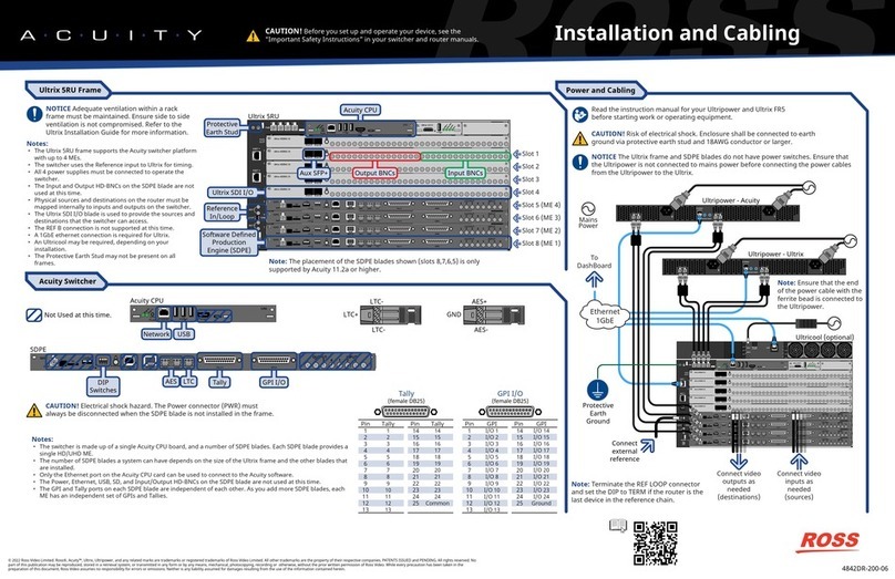
OGX-FR Cabling CAUTION
Before you set up and operate your OGX-FR see the “Important Regulatory and
Safety Notices” that shipped with your unit. It is also recommended to refer to the
OGX-FR Series User Guide. The OGX-FR Series User Guide is available for
download from our website.
Having a problem? Call our free, 24-hour technical support hotline to speak with a live
product specialist located right here in our facility.
Tel: (+1) 613 • 652 • 4886
PS1
100-240V~50-60Hz 600W
CAUTION: RISK OF SHOCK
DO NOT OPEN
!
REF 1
LOOP
REF 2
LOOP
PS2
ETHERNET
100-240V~50-60Hz 600W
CAUTION
RISK OF SHOCK
DO NOT OPEN !OGX-FR
To Redundant Power Supply To Main Power Supply
4.0 Network Cabling
WARNING
In some countries, it may be necessary to supply the correct mains
supply cord. Use only an approved IEC 320 C-13 type A/C line cord
rated for a minimum 10A at 250V and certified for the country of use.
The safe operation of this product requires that a protective ground
connection be provided. This protective ground is provided by the
grounding conductor in the equipment's supply cord. To reduce the
risk of electrical shock to operator and service personnel, this ground
conductor must be connected to a properly grounded plug. We
recommend measuring ground if unsure.
WARNING
HAZARDOUS
VOLTAGES
Tip: The OGX-FR depicted in this document includes blank plates in the rear
module slots. Your frame configuration may differ than what is depicted.
2.0 Power Connections
3.0 Reference Cabling
Note: If only one reference type is required for the OGX-FR frame, connect it to the REF 1
BNC. Two reference types enables you to use reference sources with different signal formats,
each via a separate REF BNC.
Note: Refer to the user guide for your openGear card(s) for information on the required
reference and signal types.
PS1
100-240V~50-60Hz 600W
CAUTION: RISK OF SHOCK
DO NOT OPEN
!
REF 1
LOOP
REF 2
LOOP
PS2
ETHERNET
100-240V~50-60Hz 600W
CAUTION
RISK OF SHOCK
DO NOT OPEN !OGX-FR
To Reference Source 1
To Reference Source 2
The ETHERNET port has its RJ45 connector wired as a Network Interface Card (NIC). The following table provides the wiring
information based on the type of Network Controller card installed in the OGX-FR.
PS1
100-240V~50-60Hz 600W
CAUTION: RISK OF SHOCK
DO NOT OPEN
!
REF 1
LOOP
REF 2
LOOP
PS2
ETHERNET
100-240V~50-60Hz 450W
CAUTION
RISK OF SHOCK
DO NOT OPEN !
To Ethernet Network
OGX-FR
Note: Connect the ETHERNET port to the same network as your DashBoard client
computer or to a network that has a route to the network your DashBoard client
computer is on.
Network Card
MFC-8322-S
MFC-OG3-N
MFC-OG3-N
Network Type
100BASE-TX
1000BASE-T
1000BASE-T
Frame
OGX-FR-C
OGX-FR-CN
OGX-FR-CNS
To connect to the OGX-FR from DashBoard
Note: The Network Card is pre-configured for DHCP communication. Refer to the user guide for your Network Card for details.
1. Ensure the OGX-FR is powered on.
2. Click File > New > Manual Connection.
3. In the IP Address field, enter the IP address of the Network Card in your OGX-FR chassis.
Tip: The Front Display of the OGX-FR reports the IP Address assigned to the Network Card.
4. Click Detect Settings.
5. Click Finish.


