manuals.online logo
Brands
  1. Home
  2. •
  3. Brands
  4. •
  5. Ross
  6. •
  7. Switch
  8. •
  9. Ross Ultra 4841DR-200-08 User manual

Ross Ultra 4841DR-200-08 User manual

Other Ross Switch manuals

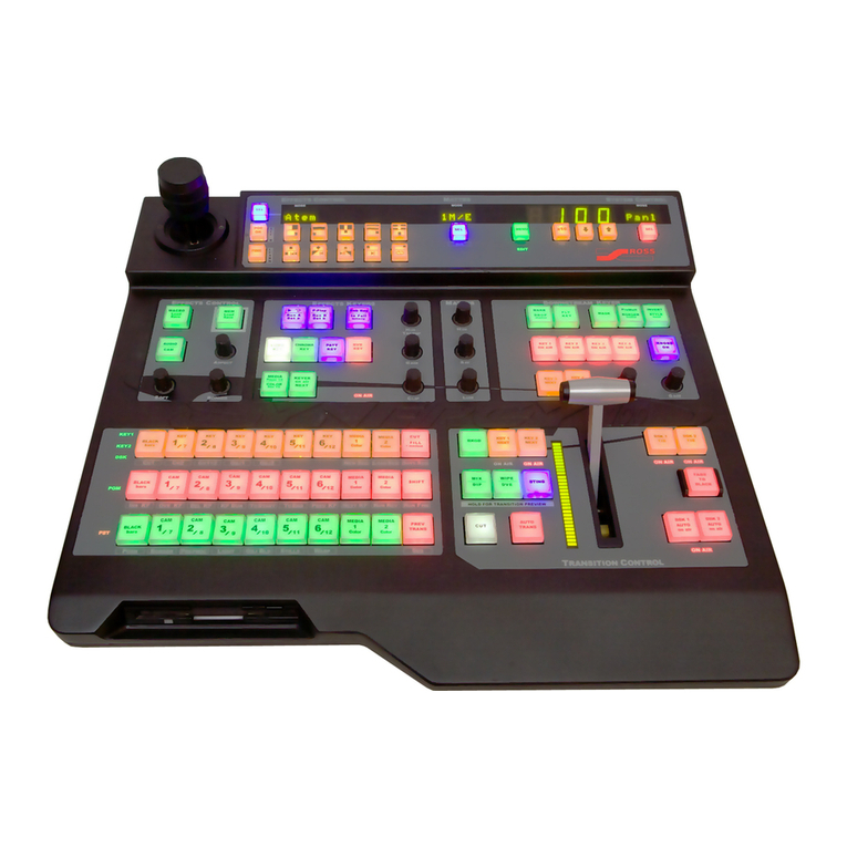
Ross Synergy 1 SD User manual

Ross

Ross Synergy 1 SD User manual

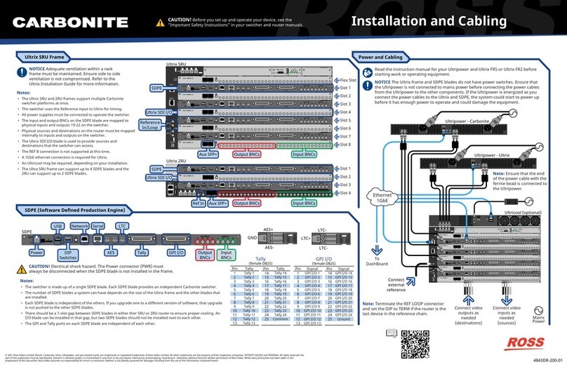
Ross Carbonite Ultra Series User manual

Ross

Ross Carbonite Ultra Series User manual

Ross Synergy 1 SD User manual

Ross

Ross Synergy 1 SD User manual

Ross Synergy 1 SD User manual

Ross

Ross Synergy 1 SD User manual

Ross Ultra 60 User manual

Ross

Ross Ultra 60 User manual

Ross Synergy 1 SD User manual

Ross

Ross Synergy 1 SD User manual

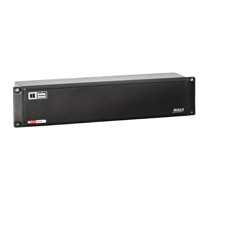
Ross NK-3G144 User manual

Ross

Ross NK-3G144 User manual

Ross Synergy Q Installation and operation manual

Ross

Ross Synergy Q Installation and operation manual

Ross Acuity User manual

Ross

Ross Acuity User manual

Ross Carbonite Series User manual

Ross

Ross Carbonite Series User manual

Ross Ultrix Carbonite User manual

Ross

Ross Ultrix Carbonite User manual

Ross Synergy 1 SD User manual

Ross

Ross Synergy 1 SD User manual

Ross Carbonite eXtreme Use and care manual

Ross

Ross Carbonite eXtreme Use and care manual

Ross Synergy Q User manual

Ross

Ross Synergy Q User manual

Ross MC1-MK User manual

Ross

Ross MC1-MK User manual

Ross Acuity Ultrix Acuity User guide

Ross

Ross Acuity Ultrix Acuity User guide

Ross CARBONITE GVG10 User manual

Ross

Ross CARBONITE GVG10 User manual

Ross Synergy 1 SD User manual

Ross

Ross Synergy 1 SD User manual

Ross Vision Squeeze & Tease User manual

Ross

Ross Vision Squeeze & Tease User manual

Ross Carbonite eXtreme Quick start guide

Ross

Ross Carbonite eXtreme Quick start guide

Ross carbonite User manual

Ross

Ross carbonite User manual

Ross carbonite User manual

Ross

Ross carbonite User manual

Ross Carbonite Black User guide

Ross

Ross Carbonite Black User guide

Ross SYNERGY 3.5 MD-X User manual

Ross

Ross SYNERGY 3.5 MD-X User manual

Popular Switch manuals by other brands

SMC Networks SMC6224M Technical specifications

SMC Networks

SMC Networks SMC6224M Technical specifications

Aeotec ZWA003-S operating manual

Aeotec

Aeotec ZWA003-S operating manual

TRENDnet TK-209i Quick installation guide

TRENDnet

TRENDnet TK-209i Quick installation guide

Planet FGSW-2022VHP user manual

Planet

Planet FGSW-2022VHP user manual

Avocent AutoView 2000  AV2000BC AV2000BC Installer/user guide

Avocent

Avocent AutoView 2000 AV2000BC AV2000BC Installer/user guide

Moxa Technologies PT-7728 Series user manual

Moxa Technologies

Moxa Technologies PT-7728 Series user manual

Intos Electronic inLine 35392I operating instructions

Intos Electronic

Intos Electronic inLine 35392I operating instructions

Cisco Catalyst 3560-X-24T Technical specifications

Cisco

Cisco Catalyst 3560-X-24T Technical specifications

Asante IntraCore IC3648 Specifications

Asante

Asante IntraCore IC3648 Specifications

Siemens SIRIUS 3SE7310-1AE Series Original operating instructions

Siemens

Siemens SIRIUS 3SE7310-1AE Series Original operating instructions

Edge-Core DCS520 quick start guide

Edge-Core

Edge-Core DCS520 quick start guide

RGBLE S00203 user manual

RGBLE

RGBLE S00203 user manual

Thrustmaster FLIGHT SIMULATOR X quick guide

Thrustmaster

Thrustmaster FLIGHT SIMULATOR X quick guide

Southwire SURGE GUARD 41390 RVC troubleshooting guide

Southwire

Southwire SURGE GUARD 41390 RVC troubleshooting guide

Buhler Nivotemp NT 61 Brief instructions

Buhler

Buhler Nivotemp NT 61 Brief instructions

Kramer VS-41HDCP user manual

Kramer

Kramer VS-41HDCP user manual

Techly IDATA AU-270 user manual

Techly

Techly IDATA AU-270 user manual

Belkin F1U109 user manual

Belkin

Belkin F1U109 user manual

manuals.online logo
manuals.online logoBrands
  • About & Mission
  • Contact us
  • Privacy Policy
  • Terms and Conditions

Copyright 2025 Manuals.Online. All Rights Reserved.

QuickStart
4841DR-200-08
© 2022 Ross Video Limited. Ross®, MiniME™, and any related marks are trademarks or registered trademarks of Ross Video Limited. All other trademarks are the property of their respective companies. PATENTS ISSUED and PENDING. All rights reserved. No part of this
publication may be reproduced, stored in a retrieval system, or transmitted in any form or by any means, mechanical, photocopying, recording or otherwise, without the prior written permission of Ross Video. While every precaution has been taken in the preparation of this
document, Ross Video assumes no responsibility for errors or omissions. Neither is any liability assumed for damages resulting from the use of the information contained herein.
CAUTION: Before you set up and operate your switcher, see the
“Important Safety Instructions” in your Setup manual.
Audio/Video Inputs/Outputs/Reference
Ports, Pinouts, and Diagnostics
Pin
1
2
3
4
5
6
7
8
RS-422
Tx+
Tx-
Rx+
n/c
n/c
Rx-
Ground
Ground
Serial
(female RJ-45)
1
2
3
4
5
6
7
8
GPI I/O
(female DB25)
1
2
3
4
5
6
7
8
9
10
11
12
13
Pin Pin
I/O 1
I/O 2
I/O 3
I/O 4
I/O 5
I/O 6
I/O 7
I/O 8
I/O 9
I/O 10
I/O 11
I/O 12
I/O 13
GPI Signal
14
15
16
17
18
19
20
21
22
23
24
25
I/O 14
I/O 15
I/O 16
I/O 17
I/O 18
I/O 19
I/O 20
I/O 21
I/O 22
I/O 23
I/O 24
Ground
1
141516171819202122232425
2345678910111213
Tally
(female DB25)
1
2
3
4
5
6
7
8
9
10
11
12
13
Pin Pin
1
2
3
4
5
6
7
8
9
10
11
12
13
Tally Tally
14
15
16
17
18
19
20
21
22
23
24
25
14
15
16
17
18
19
20
21
22
23
24
Common
1
141516171819202122232425
2345678910111213
Specifications
Video Output Specifications
Return Loss
Rise and Fall Time
Signal Level
DC Offset
Overshoot
SDI HD Mode
SDI UHD Mode
< -7.8dB @ 12Gb/s
< -15dB @ 1.5Gb/s
< -10dB @ 3Gb/s
27ps +/- 10% (UHD)
800ps +/- 10% (SD)
240ps +/- 10% (HD)
800mV +/- 10%
0 Volts
< 10%
10-bit SMPTE-292M/424M
SMPTE ST 2082-1:2015 (1:2016)
AES Output Specifications
Audio Depth
Channels
File Format
Impedance
Min/Max Output Voltage
Swing
Rise and Fall Times
Sample Rate
Synchronization
24-bit in HD
20-bit in SD
1 Stereo Pair
Multi-Channel
Waveform Audio File
110 Ohms, differential
1.5/6V peak-to-peak
20ns (typical)
48kHz
Locked to Video
Default Values
Frame IP
FTP User name
FTP Password
192.168.0.123
user
password
Tally Rating
Input Voltage:
Maximum Current:
Impedance:
24VAC (rms) / 40VDC
120mA
< 15 ohms
Temperature
Operating:
Storage:
0 - 40°C (32 - 104°F)
-20 - 85°C (-4 - 185°F)
Power
Consumption
Input Voltage
114W 7.6A 15V
100-120V~
220-240V~
47-63Hz
Power Cabling Control Cabling
Notes:
• The I/O MultiViewers are only available on MV OUT 1-2 and the Video Processor MultiViewers are only available on MV OUT 3-4.
• Audio is not embedded in the MultiViewer output.
• Only outputs 5-14 can have a FSFC assigned to them.
• In UHDTV1, only inputs 3-6 and 8-11 can accept Quad-Link 3Gb/s 2SI or QSD. All other inputs can only accept Single-Link 12Gb/s 2SI
without FSFC conversion.
Video Input Specifications
Equalization
(using Belden 1694 cable)
Impedance
Video Inputs
Reference Inputs
(non-terminating, looping)
>40m @ 12Gb/s
>100m @ 1.5 Gb/s
>300m @ 270 Mb/s (5°-40°C)
75 ohm, terminating
SMPTE 259M/292M serial digital
(non-looping)
Standard Definition — analog black
High Definition — tri-level sync
PS1 PS2
SERIAL TALLY GPIO LTC
REF
OUT 1 2 3 4 5 6 7 8 9 10 11 12 13 14IN
MV OUT OUT
1234567891011 12 13 14 15 16 17 18 19 20 21 22 23 24
IN
SD
AES1 AES2
1 2 3 4 5 6 7 8
UPGD
CUF-124
Input
HD-BNCs
Output
HD-BNCs
MultiViewer
Out
Reference
Out
Reference
In
LTC
In
AES
Out
PS1 PS2
SERIAL TALLY GPIO LTC
REF
OUT 1 2 3 4 5 6 7 8 9 10 11 12 13 14IN
MV OUT OUT
1234567891011 12 13 14 15 16 17 18 19 20 21 22 23 24
IN
SD
AES1 AES2
1 2 3 4 5 6 7 8
UPGD
TallySerial GPI I/O
DIP
Switches
Power Network
ON
OFF
POWERUPGRADE
USB Power
Switch
Mains
Power
Note: It is recommended that you always connect the AC Power
Adapter to the device before connecting to Mains Power.
Power
Switch
Power
Power
OSD
Remote
Ethernet
DashBoard
Display
(rear)
(front)
PS1 PS2
SERIAL TALLY GPIO LTC
REF
OUT 1 2 3 4 5 6 7 8 9 10 11 12 13 14IN
MV OUT OUT
1234567891011 12 13 14 15 16 17 18 19 20 21 22 23 24
IN
SD
AES1 AES2
1 2 3 4 5 6 7 8
UPGD
PS1 PS2
SERIAL TALLY GPIO LTC
REF
OUT 1 2 3 4 5 6 7 8 9 10 11 12 13 14IN
MV OUT OUT
1234567891011 12 13 14 15 16 17 18 19 20 21 22 23 24
IN
SD
AES1 AES2
1 2 3 4 5 6 7 8
UPGD
Connect video
inputs as needed
Connect external
reference or use
internal reference
Connect Program, Preview,
and aux outputs as needed
To external
serial device
To control
panel
To
DashBoard
1 2
OUT
43
RESTART
ETHERNET
RESET
Ultripower
PS1 PS2
SERIAL TALLY GPIO LTC
REF
OUT 1 2 3 4 5 6 7 8 9 10 11 12 13 14IN
MV OUT OUT
1234567891011 12 13 14 15 16 17 18 19 20 21 22 23 24
IN
SD
AES1 AES2
1 2 3 4 5 6 7 8
UPGD
OR
To external
ethernet devices
Ethernet
AES-
AES+
GND
LTC-
LTC-
LTC+
SDI Input Formats
480i 59.94Hz
576i 50Hz
720p 50/59.94/60Hz
1080i 50/59.94/60Hz
1080pSF 23.98/24/25/29.97Hz
1080p 23.98/24/25/30/29.97/30/50 (A)/59.94 (A)/60Hz
UHDTV1 23.98/24/25/29.97/30 (Single-Link 12Gb/s
2SI, Quad-Link 3Gb/s 2SI, Quad-Link 3Gb/s QSD)
1 2 3 4 5 6 7 8 9 10 11 12 13 14 15 16 17 18 19 20 21 22 23 24
IN
Single-Link 12Gb/s 2SI/QSD
Quad-Link 3Gb/s 2SI/QSD
5 6 7 8 9 10 11 12 13 14
OUT
UHD Input/Output
Printed In Canada
Having a problem? Call our free, 24-hour technical
support hotline to speak with a live product
specialist located right here in our facility.
Tel: (+1) 613 • 652 • 4886
Email: [email protected]
CAUTION: Before you set up and operate your switcher, see the
“Important Safety Instructions” in your Setup manual.
FrameGlow Diagnostics
UPGRADE: Frame is being upgraded. (cycle from yellow to white)
ON
OFF
POWERUPGRADE
BOOTING: Frame hardware is booting up. (cycle from blue to white)
ON
OFF
POWERUPGRADE
BOOTING: Frame software is booting up.
ON
OFF
POWERUPGRADE
NORMAL: Frame is operating normally. There are no warnings. Actual color is user selectable.
ON
OFF
POWERUPGRADE
WARNING: Frame is over-temperature or there is a status warning. (flashing red)
ON
OFF
POWERUPGRADE
CRITICAL: Frame is critically over-temperature. Auto power-down imminent. (solid red)
ON
OFF
POWERUPGRADE
PS1 PS2 USB
TALLY GPIO
REF
IN
OUT
TO FRAME
IN
OUT
SDI 1
PS2
PUSH PUSH PUSH PUSH PUSH PUSH PUSH PUSH
12
31
2
3
PUSH
ANALOG IN ANALOG OUT AES OUTAES IN
1 2 3 4 5 6 7 8 1 2 3 4 5 1 1
1
2
3
1
2
3
1
2
3
1
2
3
1
2
3
1
2
3
1
2
3
1
2
3
12
312
312
312
312
3
1RU Audio Breakout Module (ABM)
Analog In
from Mics
AES In/Out to
Audio Server
Mains
Power
Note: It is recommended that you always connect the AC Power Adapter to
the device before connecting to Mains Power.
PS1 PS2
SERIAL TALLY GPIO LTC
REF
OUT 1 2 3 4 5 6 7 8 9 10 11 12 13 14IN
MV OUT OUT
1234567891011 12 13 14 15 16 17 18 19 20 21 22 23 24
IN
SD
AES1 AES2
1 2 3 4 5 6 7 8
UPGD
Analog
Outputs
SDI-Audio Loop
(IN24 to OUT)
(OUT14 to IN)
ABM 1 — IN24 to OUT / OUT14 to IN
ABM 2 — IN23 to OUT / OUT13 to IN
ABM 3 — IN22 to OUT / OUT12 to IN
Important: Ensure that Phantom Power is turned off for the Analog Input unless you are connecting a micro-
phone that requires phantom power. Connecting the line out from an audio device to the analog input with phan-
tom power on could damage the audio device and/or the 1RU Audio Breakout Module. For added safety, a TRS
phone connecter should be used for line in audio sources.
Note: Support for the 1RU Audio Breakout Module (ABM) is not available in UHDTV1 at this time.
Analog Audio Input Specifications
Input Impedance
Maximum Level
Frequency Response
Signal to Noise Ratio
“A” weighting
CCITT weighting
THD
Amplitude Linearity
Crosstalk
XLR: 2K ohm
¼” Jack: 10K ohm
+24dBu
±0.3dB (22Hz to
20kHz @ Fs = 48kHz)
-95dB
-98dB
-107dB
>93dB or <0.002%
<0.8dB @ -100dBFS
-94dB
Analog Audio Output Specifications
Maximum Level
Frequency Response
Signal to Noise Ratio
THD
Amplitude Linearity
Crosstalk
+24dBu
±0.4dB (22Hz to
20kHz @ Fs = 48kHz)
-103dB
>93dB
<0.3dB @ -100dBFS
-106dB (20Hz to
20kHz)
Power Consumption
Audio Breakout
Module
45W 3.75A 12V