manuals.online logo
Brands
  1. Home
  2. •
  3. Brands
  4. •
  5. Ross
  6. •
  7. Switch
  8. •
  9. Ross Acuity Ultrix 5RU User manual

Ross Acuity Ultrix 5RU User manual

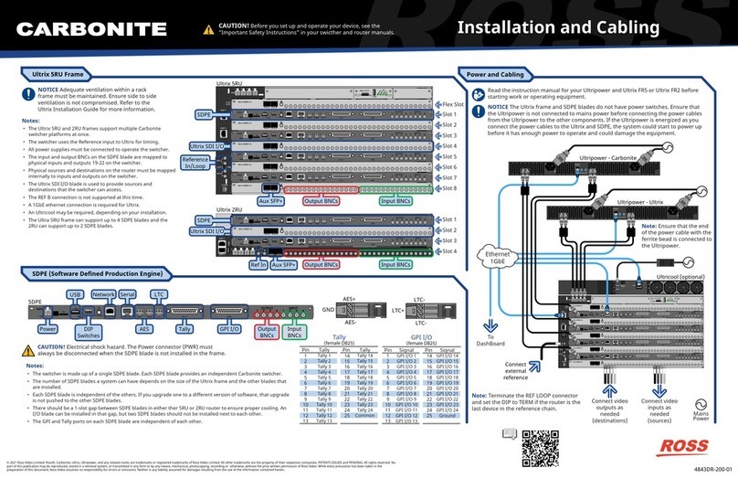
Installation and Cabling
4842DR-200-02
© 2021 Ross Video Limited. Ross®, Acuity™, Ultrix, Ultripower, and any related marks are trademarks or registered trademarks of Ross Video Limited. All other trademarks are the property of their respective companies. PATENTS ISSUED and PENDING. All rights reserved. No
part of this publication may be reproduced, stored in a retrieval system, or transmitted in any form or by any means, mechanical, photocopying, recording or otherwise, without the prior written permission of Ross Video. While every precaution has been taken in the
preparation of this document, Ross Video assumes no responsibility for errors or omissions. Neither is any liability assumed for damages resulting from the use of the information contained herein.
SD
PWR
SDPE
ETHERNET EDITOR AES1 AES2 LTC TALLY GPIO
OUTPUT INPUT
12341234
1 2 3 4
8-10in-lbs
UPGD
SD
PWR
SDPE
ETHERNET EDITOR AES1 AES2 LTC TALLY GPIO
OUTPUT INPUT
12341234
1 2 3 4
8-10in-lbs
UPGD
SD
PWR
SDPE
ETHERNET EDITOR AES1 AES2 LTC TALLY GPIO
OUTPUT INPUT
12341234
1 2 3 4
8-10in-lbs
UPGD
SD
PWR
SDPE
ETHERNET EDITOR AES1 AES2 LTC TALLY GPIO
OUTPUT INPUT
12341234
1 2 3 4
8-10in-lbs
UPGD
ENET 1
ENET 2
REF A
LOOP
TERM
A
B
REF B
ALARM
FLEX
SLOT
PWR
1 2 3 4
Ultrix-HDBNC-IO
AUX A AUX B
Ultrix-HDBNC-IO
AUX A AUX B
Ultrix-HDBNC-IO
AUX A AUX B
Ultrix-HDBNC-IO
AUX A AUX B
Ultrix-HDBNC-IO
AUX A AUX B
Ultrix-UCCI
Status
Prim/Sec
Alarm
Aux
ETHERNET
CPU
Power
HDMI
CPU
Status
Alarm
1 2
OUT
43
RESTART
ETHERNET
RESET
Ultripower - Ultrix
1 2
OUT
43
RESTART
ETHERNET
RESET
Ultripower - Acuity
Ultrix 5RU Frame
Acuity Switcher
CAUTION! Before you set up and operate your device, see the
“Important Safety Instructions” in your swicther and router manuals.
Power and Cabling
5
ENET
1
2
3
4
6PWR 1 NO C NC
ALARM
PWR 2
7
8
Connect
external
reference
Connect video
inputs as
needed
(sources)
Connect video
outputs as
needed
(destinations)
Mains
Power
Notes:
• The Ultrix 5RU frame supports the Acuity switcher
platform with up to 4 MEs.
• The switcher uses the Reference input to Ultrix for timing.
• All 4 power supplies must be connected to operate the
switcher.
• The Input and Output HD-BNCs on the SDPE blade are
not used at this time.
• Physical sources and destinations on the router must be
mapped internally to inputs and outputs on the switcher.
• The Ultrix SDI I/O blade is used to provide the sources
and destinations that the switcvher can access.
• The REF B connection is not supported at this time.
• A 1GbE ethernet connection is required for Ultrix.
• An Ultricool may be required, depending on your
installation.
Notes:
• The switcher is made up of a single Acuity CPU board, and a number of SDPE blades. Each SDPE blade provides a single HD/UHD ME.
• The number of SDPE blades a system can have depends on the size of the Ultrix frame and the other blades that are installed.
• Only the Ethernet port on the Acuity CPU card can be used to connect to the Acuity software.
• The Ethernet, USB, SD, and Input/Output HD-BNCs on the SDPE blade are not used at this time.
• The GPI and Tally ports on each SDPE blade are independent of each other. As you add more SDPE blades, each ME has an independent set of
GPIs and Tallies.
ETHERNET
CPU
Power HDMI
CPU
Status
Alarm
Network USB
Acuity CPU
SD
PWR
SDPE
ETHERNET EDITOR AES1 AES2 LTC TALLY GPIO
OUTPUT INPUT
12341234
1 2 3 4
8-10in-lbs
UPGD
GPI I/OTallyPower DIP
Switches
SDPE
SD
PWR
SDPE
ETHERNET EDITOR AES1 AES2 LTC TALLY GPIO
OUTPUT INPUT
12341234
1 2 3 4
8-10in-lbs
UPGD
SD
PWR
SDPE
ETHERNET EDITOR AES1 AES2 LTC TALLY GPIO
OUTPUT INPUT
12341234
1 2 3 4
8-10in-lbs
UPGD
SD
PWR
SDPE
ETHERNET EDITOR AES1 AES2 LTC TALLY GPIO
OUTPUT INPUT
12341234
1 2 3 4
8-10in-lbs
UPGD
SD
PWR
SDPE
ETHERNET EDITOR AES1 AES2 LTC TALLY GPIO
OUTPUT INPUT
12341234
1 2 3 4
8-10in-lbs
UPGD
ENET 1
ENET 2
REF A
LOOP
TERM
A
B
REF B
ALARM
FLEX
SLOT
PWR
1 2 3 4
Ultrix-HDBNC-IO
AUX A AUX B
Ultrix-HDBNC-IO
AUX A AUX B
Ultrix-HDBNC-IO
AUX A AUX B
Ultrix-HDBNC-IO
AUX A AUX B
Ultrix-HDBNC-IO
AUX A AUX B
Ultrix-UCCI
Status
Prim/Sec
Alarm
Aux
ETHERNET
CPU
Power
HDMI
CPU
Status
Alarm
Ultrix 5RU
Aux SFP+
Acuity CPU
Software Defined
Production
Engine (SDPE)
Ultrix SDI I/O
Reference
In/Loop
Input BNCsOutput BNCs
Slot 1 (ME 1)
Slot 2
Slot 3 (ME 2)
Slot 4
Slot 5 (ME 3)
Slot 6
Slot 7 (ME 4)
Slot 8
GPI I/O
(female DB25)
1
2
3
4
5
6
7
8
9
10
11
12
13
Pin Pin
GPI I/O 1
GPI I/O 2
GPI I/O 3
GPI I/O 4
GPI I/O 5
GPI I/O 6
GPI I/O 7
GPI I/O 8
GPI I/O 9
GPI I/O 10
GPI I/O 11
GPI I/O 12
GPI I/O 13
Signal Signal
14
15
16
17
18
19
20
21
22
23
24
25
GPI I/O 14
GPI I/O 15
GPI I/O 16
GPI I/O 17
GPI I/O 18
GPI I/O 19
GPI I/O 20
GPI I/O 21
GPI I/O 22
GPI I/O 23
GPI I/O 24
Ground
Tally
(female DB25)
1
2
3
4
5
6
7
8
9
10
11
12
13
Pin Pin
Tally 1
Tally 2
Tally 3
Tally 4
Tally 5
Tally 6
Tally 7
Tally 8
Tally 9
Tally 10
Tally 11
Tally 12
Tally 13
Tally Tally
14
15
16
17
18
19
20
21
22
23
24
25
Tally 14
Tally 15
Tally 16
Tally 17
Tally 18
Tally 19
Tally 20
Tally 21
Tally 22
Tally 23
Tally 24
Common
AES-
AES+
GND
LTC-
LTC-
LTC+
Read the instruction manual for your Ultripower and Ultrix FR5
before starting work or operating equipment.
NOTICE The Ultrix frame and SDPE blades do not have power switches. Ensure that
the Ultripower is not connected to mains power before connecting the power cables
from the Ultripower to the other components. If the Ultripower is energized as you
connect the power cables to the Ultrix and SDPE, the system could start to power up
before it has enough power to operate and could damage the equipment.
NOTICE Adequate ventilation within a rack
frame must be maintained. Ensure side to side
ventilation is not compromised. Refer to the
Ultrix Installation Guide for more information.
CAUTION! Electrical shock hazard. The Power connector (PWR) must
always be disconnected when the SDPE blade is not installed in the frame.
Note: Terminate the REF LOOP connector
and set the DIP to TERM if the router is the
last device in the reference chain.
Note: Ensure that the end
of the power cable with the
ferrite bead is connected to
the Ultripower.
To
DashBoard
Ultricool (optional)
Ethernet
1GbE
Not Used at this time.
Powering Up/Down
Printed In Canada
Having a problem? Call our free, 24-hour technical
support hotline to speak with a live product
specialist located right here in our facility.
Tel (North America): 1-844-652-0645
Tel (International): +800 1005 0100
Email: [email protected]
Note: To power down the Utrix Acuity, power down the Ultripower - Ultrix
first and then the Ultripower - Acuity.
1
1 2
OUT
43
RESTART
ETHERNET
RESET
Ultripower - Ultrix
DashBoard - Ultripower
1 2
OUT
43
RESTART
ETHERNET
RESET
Ultripower - Acuity
Ultripower Connection
1. Connect an Ultripower unit to mains power.
Important: Do NOT connect them to the Ultrix Acuity.
2. Connect to one of the Ultripower units from DashBoard.
3. Click Change in the Device Power State to turn the power off.
4. Wait for the Avg Output (W) to go to 0.
5. On the Setup tab, name the first power supply Ultrix and assign all the
power supplies to that label.
6. Repeat for the other Ultripower and name it Acuity.
2Ultrix Acuity Power Connection
1. Connect the Ultripower - Acuity to the SDPE blades.
2. Connect the Ultripower - Ultrix to the Ultrix.
Ethernet
1GbE
3Ultrix Acuity Power Up
1. Connect to the Ultripower - Acuity in DashBoard.
2. Click Change in the Device Power State to turn the power on.
3. Wait for the Avg Output (W) to rise and stabalize. It should only take a
few seconds.
4. Connect to the Ultripower - Ultrix in DashBoard.
5. Click Change in the Device Power State to turn the power on.
6. Wait for the Avg Output (W) to rise and stabalize. It should only take a
few seconds.
7. The Ultrix Acuity should be booting up safely now.
SD
PWR
SDPE
ETHERNET EDITOR AES1 AES2 LTC TALLY GPIO
OUTPUT INPUT
12341234
1 2 3 4
8-10in-lbs
UPGD
SD
PWR
SDPE
ETHERNET EDITOR AES1 AES2 LTC TALLY GPIO
OUTPUT INPUT
12341234
1 2 3 4
8-10in-lbs
UPGD
SD
PWR
SDPE
ETHERNET EDITOR AES1 AES2 LTC TALLY GPIO
OUTPUT INPUT
12341234
1 2 3 4
8-10in-lbs
UPGD
SD
PWR
SDPE
ETHERNET EDITOR AES1 AES2 LTC TALLY GPIO
OUTPUT INPUT
12341234
1 2 3 4
8-10in-lbs
UPGD
ENET 1
ENET 2
REF A
LOOP
TERM
A
B
REF B
ALARM
FLEX
SLOT
PWR
1 2 3 4
Ultrix-HDBNC-IO
AUX A AUX B
Ultrix-HDBNC-IO
AUX A AUX B
Ultrix-HDBNC-IO
AUX A AUX B
Ultrix-HDBNC-IO
AUX A AUX B
Ultrix-HDBNC-IO
AUX A AUX B
Ultrix-UCCI
Status
Prim/Sec
Alarm
Aux
ETHERNET
CPU
Power
HDMI
CPU
Status
Alarm
1 2
OUT
43
RESTART
ETHERNET
RESET
Ultripower - Ultrix
1 2
OUT
43
RESTART
ETHERNET
RESET
Ultripower - Acuity
DashBoard - Ultripower

Other Ross Switch manuals

Ross Ultrix Carbonite User manual

Ross

Ross Ultrix Carbonite User manual

Ross Ultra 4841DR-200-08 User manual

Ross

Ross Ultra 4841DR-200-08 User manual

Ross Synergy 1 SD User manual

Ross

Ross Synergy 1 SD User manual

Ross Carbonite Series User guide

Ross

Ross Carbonite Series User guide

Ross Synergy 1 SD User manual

Ross

Ross Synergy 1 SD User manual

Ross Acuity User manual

Ross

Ross Acuity User manual

Ross Carbonite eXtreme Use and care manual

Ross

Ross Carbonite eXtreme Use and care manual

Ross Synergy 1 SD User manual

Ross

Ross Synergy 1 SD User manual

Ross Synergy 2 SD User manual

Ross

Ross Synergy 2 SD User manual

Ross Carbonite Black Solo User manual

Ross

Ross Carbonite Black Solo User manual

Ross Carbonite Black Series User manual

Ross

Ross Carbonite Black Series User manual

Ross ACO-2200 User manual

Ross

Ross ACO-2200 User manual

Ross Acuity 4810AR-002 User guide

Ross

Ross Acuity 4810AR-002 User guide

Ross Carbonite eXtreme Quick start guide

Ross

Ross Carbonite eXtreme Quick start guide

Ross Carbonite Black Solo User manual

Ross

Ross Carbonite Black Solo User manual

Ross Synergy Q Installation and operation manual

Ross

Ross Synergy Q Installation and operation manual

Ross carbonite User guide

Ross

Ross carbonite User guide

Ross Carbonite Ultra User manual

Ross

Ross Carbonite Ultra User manual

Ross SYNERGY 3.5 MD-X User manual

Ross

Ross SYNERGY 3.5 MD-X User manual

Ross Synergy 1 SD User manual

Ross

Ross Synergy 1 SD User manual

Ross CARBONITE GVG10 User manual

Ross

Ross CARBONITE GVG10 User manual

Ross Carbonite Black User guide

Ross

Ross Carbonite Black User guide

Ross Carbonite Series User manual

Ross

Ross Carbonite Series User manual

Ross Carbonite Solo User manual

Ross

Ross Carbonite Solo User manual

Popular Switch manuals by other brands

ADDER AdderView Prism user guide

ADDER

ADDER AdderView Prism user guide

Cisco 300 Series Cli guide

Cisco

Cisco 300 Series Cli guide

Surecom EP-508 user guide

Surecom

Surecom EP-508 user guide

Linkskey LKV-S02ASK Quick installation guide

Linkskey

Linkskey LKV-S02ASK Quick installation guide

Edimax ES-5500M V2 datasheet

Edimax

Edimax ES-5500M V2 datasheet

EtherWAN EX43000 series quick start guide

EtherWAN

EtherWAN EX43000 series quick start guide

Bticino K4003CW quick start guide

Bticino

Bticino K4003CW quick start guide

Mosa SIP 4600B user manual

Mosa

Mosa SIP 4600B user manual

HPE FlexNetwork 10500 SERIES Configuration guide

HPE

HPE FlexNetwork 10500 SERIES Configuration guide

Alpine VPA-B211P owner's manual

Alpine

Alpine VPA-B211P owner's manual

EUCHNER CES-A-C5H-01-EX operating instructions

EUCHNER

EUCHNER CES-A-C5H-01-EX operating instructions

Edimax EK-PAK2 Quick installation guide

Edimax

Edimax EK-PAK2 Quick installation guide

Southern States EV-2 Installation reference guide

Southern States

Southern States EV-2 Installation reference guide

Siemens 3WN Series operating instructions

Siemens

Siemens 3WN Series operating instructions

HPE FlexFabric 7900 Series Command reference

HPE

HPE FlexFabric 7900 Series Command reference

Texas Instruments ThunderSWITCH TNETX3270 s manual

Texas Instruments

Texas Instruments ThunderSWITCH TNETX3270 s manual

Asus GIGAX 2024M user guide

Asus

Asus GIGAX 2024M user guide

LQ GROUP 1145616-00000 instruction manual

LQ GROUP

LQ GROUP 1145616-00000 instruction manual

manuals.online logo
manuals.online logoBrands
  • About & Mission
  • Contact us
  • Privacy Policy
  • Terms and Conditions

Copyright 2025 Manuals.Online. All Rights Reserved.