PAGE 2 of 2
Before you begin...
4Ensure that you have sufficient space to work and allow at
least ONE HOUR for assembly, particularly if you have never
built a unit before. We recommend two-person assembly.
4Always use a rubber mallet for assembly and NEVER
a metal hammer. Please note: force is required! The
components are designed to fit tightly together so that they
don’t wobble or break apart, so a light tap will NOT locate the
parts sufficiently.
4We recommend wearing gloves when assembling.
Thank you for purchasing your
ShelvingDirect® shelving
If you have any questions regarding the
assembly or contents of your order, please call
ShelvingDirect® on 0121 508 5877
Monday to Friday 8.30am–5.30pm or email
sales@shelvingdirect.co.uk
ShelvingDirect® is a trading name of Rotadex
Systems Ltd, Systems House, Central Business Park,
Mackadown Lane, Birmingham B33 0JL.
Assembly instructions
STEP 1: Arrange the four uprights [A] so that the
“keyholes” have the larger aperture uppermost:
STEP 2: Begin by attaching the heavy duty plastic feet [B] to the
base of the upright posts.
STEP 3: With one person holding two uprights parallel, join them
by adding a side beam [C] near the top (at the desired level for the
uppermost shelf) by striking its lugs firmly down into the “keyholes”
of the uprights using a rubber mallet. Force is required. NOTE:
the lugs do not need to go completely to the bottom of the
keyholes. Pinch the side beam and upright together using thumb
and forefinger directly between the lugs to ensure they are located
before hammering.
STEP 4: Add a second side beam [C] near the bottom and at the
desired level for the lower shelf level.
STEP 5: Add the remaining two side beams [C], spacing them as
you require. Using this first sub-assembly as a ‘spacing guide’,
repeat this process with the other two uprights to create another
“ladder”. These form the left and right sides of your shelving unit.
STEP 6: Take a cross beam [D] and join the two “ladders” together
by attaching it near the top, at the same height as the uppermost
side beams. Repeat at the bottom.
STEP 7: Add cross beams [D] to the back of the unit too, and fit all
remaining cross beams ensuring they are located at the same height
as their corresponding side beams [C].
STEP 8: If you have purchased an 1800mm+ wide unit, tap in the
centre support beams [E].You may need to push the cross beams
[D] towards one-another to do this.
STEP 9: Lastly, add the shelf levels [F].You will find it easier to
swivel the shelves in at an angle. The shelves are slightly smaller
than the space they fill, to aid assembly.
[C]
[D]
[E]
[F]
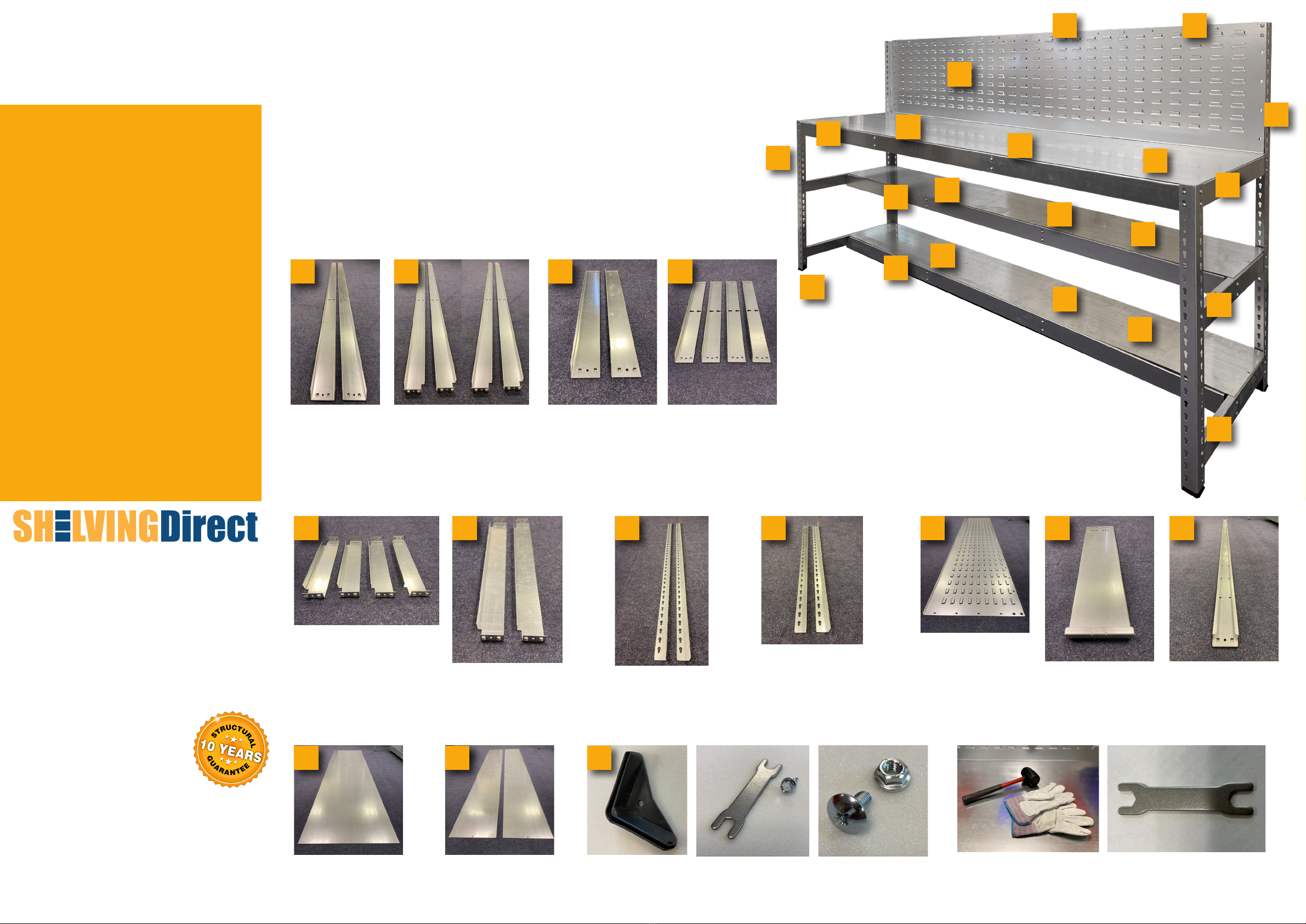
GALV WORKBENCH + LOUVRE PANEL
ASSEMBLY INSTRUCTIONS
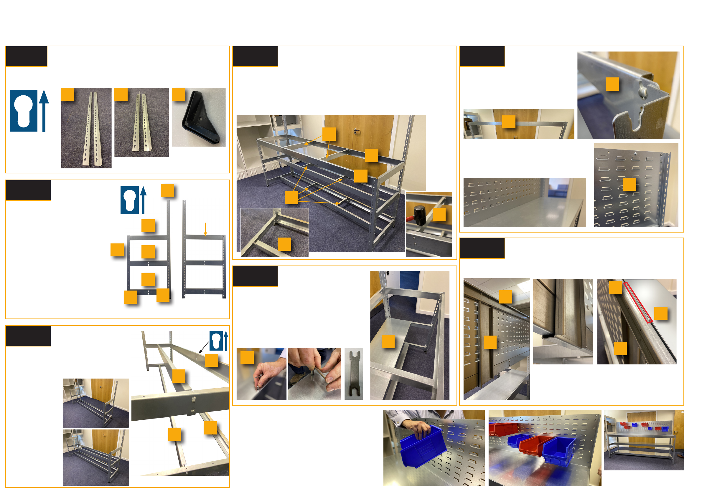
Arrange the four uprights [G, H] so that the “keyholes’ have the larger
aperture uppermost. Add the four plastic feet [N] to bottom of each upright.
G H N
“Keyholes”
MUST
have the
larger aperture
uppermost!
With one person holding one tall upright
[G] and one short upright [H] parallel,
join them by adding side beams [C, D]
as pictured. Use the rubber mallet to
strike the sidebeams’ lugs rmly down
in the the “keyholes”.
FORCE IS REQUIRED!
Pinch the side beam and upright
together using thumb and forenger
to ensure lugs and holes are located
before hammering. IMPORTANT:
ensure [D] side beams are used for
the two lower beams, and side beam
[C] as the upper beam. Repeat this
process to create the other end of your
workbench.
G
H
C
D
D
Assemble both ends of the workbench
Before you begin...
4Ensure that you have sufficient space to work and allow at
least ONE HOUR for assembly, particularly if you have never
built a unit before. We recommend two-person assembly.
4Always use a rubber mallet for assembly and NEVER
a metal hammer. Please note: force is required! The
components are designed to fit tightly together so that they
don’t wobble or break apart, so a light tap will NOT locate the
parts sufficiently.
4We recommend wearing gloves when assembling.
Thank you for purchasing your
ShelvingDirect® shelving
If you have any questions regarding the
assembly or contents of your order, please call
ShelvingDirect® on 0121 508 5877
Monday to Friday 8.30am–5.30pm or email
sales@shelvingdirect.co.uk
ShelvingDirect® is a trading name of Rotadex
Systems Ltd, Systems House, Central Business Park,
Mackadown Lane, Birmingham B33 0JL.
Assembly instructions
STEP 1: Arrange the four uprights [A] so that the
“keyholes” have the larger aperture uppermost:
STEP 2: Begin by attaching the heavy duty plastic feet [B] to the
base of the upright posts.
STEP 3: With one person holding two uprights parallel, join them
by adding a side beam [C] near the top (at the desired level for the
uppermost shelf) by striking its lugs firmly down into the “keyholes”
of the uprights using a rubber mallet. Force is required. NOTE:
the lugs do not need to go completely to the bottom of the
keyholes. Pinch the side beam and upright together using thumb
and forefinger directly between the lugs to ensure they are located
before hammering.
STEP 4: Add a second side beam [C] near the bottom and at the
desired level for the lower shelf level.
STEP 5: Add the remaining two side beams [C], spacing them as
you require. Using this first sub-assembly as a ‘spacing guide’,
repeat this process with the other two uprights to create another
“ladder”. These form the left and right sides of your shelving unit.
STEP 6: Take a cross beam [D] and join the two “ladders” together
by attaching it near the top, at the same height as the uppermost
side beams. Repeat at the bottom.
STEP 7: Add cross beams [D] to the back of the unit too, and fit all
remaining cross beams ensuring they are located at the same height
as their corresponding side beams [C].
STEP 8: If you have purchased an 1800mm+ wide unit, tap in the
centre support beams [E].You may need to push the cross beams
[D] towards one-another to do this.
STEP 9: Lastly, add the shelf levels [F].You will find it easier to
swivel the shelves in at an angle. The shelves are slightly smaller
than the space they fill, to aid assembly.
[C]
[D]
[E]
[F]
GALV WORKBENCH + LOUVRE PANEL
BB
BB
B
B
Before you begin...
4Ensure that you have sufficient space to work and allow at
least ONE HOUR for assembly, particularly if you have never
built a unit before. We recommend two-person assembly.
4Always use a rubber mallet for assembly and NEVER
a metal hammer. Please note: force is required! The
components are designed to fit tightly together so that they
don’t wobble or break apart, so a light tap will NOT locate the
parts sufficiently.
4We recommend wearing gloves when assembling.
Thank you for purchasing your
ShelvingDirect® shelving
If you have any questions regarding the
assembly or contents of your order, please call
ShelvingDirect® on 0121 508 5877
Monday to Friday 8.30am–5.30pm or email
sales@shelvingdirect.co.uk
ShelvingDirect® is a trading name of Rotadex
Systems Ltd, Systems House, Central Business Park,
Mackadown Lane, Birmingham B33 0JL.
Assembly instructions
STEP 1: Arrange the four uprights [A] so that the
“keyholes” have the larger aperture uppermost:
STEP 2: Begin by attaching the heavy duty plastic feet [B] to the
base of the upright posts.
STEP 3: With one person holding two uprights parallel, join them
by adding a side beam [C] near the top (at the desired level for the
uppermost shelf) by striking its lugs firmly down into the “keyholes”
of the uprights using a rubber mallet. Force is required. NOTE:
the lugs do not need to go completely to the bottom of the
keyholes. Pinch the side beam and upright together using thumb
and forefinger directly between the lugs to ensure they are located
before hammering.
STEP 4: Add a second side beam [C] near the bottom and at the
desired level for the lower shelf level.
STEP 5: Add the remaining two side beams [C], spacing them as
you require. Using this first sub-assembly as a ‘spacing guide’,
repeat this process with the other two uprights to create another
“ladder”. These form the left and right sides of your shelving unit.
STEP 6: Take a cross beam [D] and join the two “ladders” together
by attaching it near the top, at the same height as the uppermost
side beams. Repeat at the bottom.
STEP 7: Add cross beams [D] to the back of the unit too, and fit all
remaining cross beams ensuring they are located at the same height
as their corresponding side beams [C].
STEP 8: If you have purchased an 1800mm+ wide unit, tap in the
centre support beams [E].You may need to push the cross beams
[D] towards one-another to do this.
STEP 9: Lastly, add the shelf levels [F].You will find it easier to
swivel the shelves in at an angle. The shelves are slightly smaller
than the space they fill, to aid assembly.
[C]
[D]
[E]
[F]
GALV WORKBENCH + LOUVRE PANEL
Your workbench
should now
look like the one
pictured here
Join the end pieces created in Step 2 together
using the four 2400mm width beams [B], as
pictured right. Ensure that the keyholes in the
width beams are the correct way up.
Starting at the
bottom, connect
the end pieces
with the width
beams
Add the remaining two 2400mm upper width beams [A] to the unit, then
link all width beams using the four 310mm shelf supports [E] and the two 600mm
shelf supports [F], as pictured. Hammer these shelf supports down in the “keyholes”
on the cross beams to provide a tight grip. IMPORTANT: You may need to apply
pressure to the cross beams in order to bring them closer together to enable the
shelf supports to be inserted. This helps give the workbench overall stability.
Place all three steel shelves onto the unit [L] and
[M] and secure by xing the self tapping screws
into the holes in the ends of the shelves. Tighten
with spanner provided (or a socket, if you have
one). IMPORTANT: There are holes on the front
edge of the upper shelf which are part of the
manufacturing process, and do not need to have
screws inserted into them.
A
A
E
F
E
M
You are now ready to add the louvre
panel to your workbench. Begin by
adding the nal cross beam [K] to the
top “keyholes” of the rear uprights
(picture right and below).
K
K
Next, add the louvre panel to the rear of the
workbench, ensuring it is the correct way up
(as picture). Use the supplied bolts and nuts to
x the louvre panel to the rear uprights and cross
beam through the holes provided.
I
Finally, add the upright louvre beam [J] to the rear centre point of the [K] beam
using two bolts with serated nuts in the upper two holes.
J
K
ABOVE: The upright
louvre beam should hook
under the lower rear
cross beam.
ABOVE: The top of the upright
louvre beam [J] should slot between
the [K] beam and the louvre panel
[I], and is held in place by two bolts
and nuts that should pass through
all three components.
J
K
I
Optional Pick Bins
If you have purchased pick bins to use with your unit,
ensure that they are correctly tted to the louvre
panel, as pictured. For accessories or help, please
see www.shelvingdirect.co.uk or call us.
STEP 2
STEP 1
STEP 3
STEP 4
STEP 5
STEP 6
STEP 7
The uppermost
side beam does
NOT have a
“keyhole” at its
centre F
L
Tel: 0121 508 5877