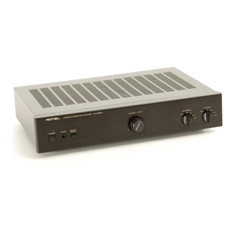
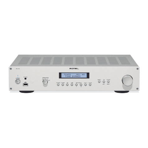
Rotel RA-05 User manual

RA-05
Stereo Integrated Amplifier
Amplificateur Intégré Stéréophonique
Stereo-Vollverstärker
Amplificatore Integrato Estereofonico
Amplificador Integrado Estereofónico
Geïntegreerde Stereo Versterker
Integrerad Stereoförstärkare
Стерео интегрированный усилитель
Owner’s Manual
Manuel de l’utilisation
Bedienungsanleitung
Manuale di Istruzioni
Manual de Instrucciones
Gebruiksaanwijzing
Instruktionsbok
Инструкция Пользователя

2
RA-05 Stereo Integrated Amplifier
Important Safety Instructions
WARNING: There are no user serviceable parts inside. Refer
all servicing to qualified service personnel.
WARNING: To reduce the risk of fire or electric shock, be
sure that the apparatus shall not be exposed to dripping
or splashing and that no objects filled with liquids, such as
vases, shall be placed on the apparatus.
Do not allow foreign objects to get into the enclosure. If the
unit is exposed to moisture, or a foreign object gets into the
enclosure, immediately disconnect the power cord from the
wall. Take the unit to a qualified service person for inspec-
tion and necessary repairs.
Read all the instructions before connecting or operating the component.
Keep this manual so you can refer to these safety instructions.
Heed all warnings and safety information in these instructions and on the
product itself. Follow all operating instructions.
Clean the enclosure only with a dry cloth or a vacuum cleaner.
You must allow 10 cm or 4 inches of unobstructed clearance
around the unit. Do not place the unit on a bed, sofa, rug, or similar
surface that could block the ventilation slots. If the component is placed in
a bookcase or cabinet, there must be ventilation of the cabinet to allow
proper cooling.
Keep the component away from radiators, heat registers, stoves, or any
other appliance that produces heat.
The unit must be connected to a power supply only of the type and voltage
specified on the rear panel of the unit.
Connect the component to the power outlet only with the supplied
power supply cable or an exact equivalent. Do not modify the
supplied cable in any way. Do not attempt to defeat grounding and/or
polarization provisions. Do not use extension cords.
Do not route the power cord where it will be crushed, pinched, bent at severe
angles, exposed to heat, or damaged in any way. Pay particular attention
to the power cord at the plug and where it exits the back of the unit.
The power cord should be unplugged from the wall outlet if the unit is to
be left unused for a long period of time.
Immediately stop using the component and have it inspected and/or serviced
by a qualified service agency if:
• The power supply cord or plug has been damaged.
• Objects have fallen or liquid has been spilled into the unit.
• The unit has been exposed to rain.
• The unit shows signs of improper operation
• The unit has been dropped or damaged in any way
Please use Class 2 Wiring when connecting the speaker terminals of the unit
to ensure proper insulation and minimize the risk of electrical shock.
Place the unit on a fixed, level surface strong enough to
support its weight. Do not place it on a moveable cart
that could tip over.
This symbol means that this unit is double insulated. An earth con-
nection is not required.
Rotel products are designed to comply with international di-
rectives on the Restriction of Hazardous Substances (RoHS) in
electrical and electronic equipment and the disposal of Waste
Electrical and Electronic Equipment (WEEE). The crossed
wheelie bin symbol indicates compliance and that the products
must be appropriately recycled or processed in accordance
with these directives.

3English
Figure 1: Controls and Connections
Commandes et branchements
Bedienelemente und Anschlüsse
Pannello frontale e posteriore
Controles y Conexiones
De bedieningsorganen en de aansluitingen
Funktioner och anslutningar
Органы управления и разъемы
RR-AT94
10
POWER
PTY TA
MEM
MONO
TP DISPLAY
DIRECT BAND
+ 10
RANDOM
1 2 3
4 5 6
7 8
0
9
PHO
AUX 1 AUX 2 TP 1 TP 2
T/P
CD TUN
TUNING
VOLUME
MUTE
a s
f
d
RA-05
H=60 mm
2
3
7890 - =qw
4
5
6
RA-05
AUX 1
AUX 2
CD
TUNER
PHONO
PHONES
MEDIA
PL AYER
BALANCE
POWER
SOURCE
TAPE
A
OF F B
A+ B
TREBLEBASS
SPEAKERS
TONE
ON
18
28
1
[ ] \
e r t y u i op

4
Figure 2: Signal Input and Speaker Output Connections
Signaux d’entrée et branchements enceintes acoustiques
Signaleingang und Anschluss eines Lautsprecherpaares
Schema dei collegamenti
Conexiones para Entrada de Señal y Salida a las Cajas Acústicas
Het aansluiten van de lijnbronnen, een opname/weergaveapparaat en de luidsprekers
Anslutningar för ingångssignalerna och högtalarutgångarna
Подсоединение источников сигнала и акустических систем
RA-05 Stereo Integrated Amplifier
Warning: Turn off this unit and the entire system
before making connections!
Attention: éteignez cet appareil et le système
complet avant d’effectuer le moindre
branchement !!
Warnung: Schalten Sie dieses Gerät und das
gesamte System vor dem Anschließen
ab!
Attenzione: Spegnete l’unità e l’intero sistema
prima di effettuare le connessioni!
¡Advertencia! Antes de realizar cualquier tipo de
conexión, desactive este aparato y
el resto del equipo.
Waarschuwing: Schakel dit apparaat en het gehele
systeem uit voordat u verbindingen
maakt!
Varning: Stäng av denna enhet samt hela
systemet innan anslutningar utförs!
Предупреждение: Выключите устройство и всю систему
перед соединением!

5
About Rotel
A family whose passionate interest in music led
them to manufacture high fidelity components
of uncompromising quality founded Rotel over
40 years ago. Through the years that passion
has remained undiminished and the family goal
of providing exceptional value for audiophiles
and music lovers regardless of their budget, is
shared by all Rotel employees.
The engineers work as a close team, listening
to, and fine tuning each new product until it
reaches their exacting musical standards. They
are free to choose components from around
the world in order to make that product the
best they can. You are likely to find capacitors
from the United Kingdom and Germany, semi
conductors from Japan or the United States,
while toroidal power transformers are manu-
factured in Rotel’s own factory.
Rotel’s reputation for excellence has been
earned through hundreds of good reviews and
awards from the most respected reviewers in
the industry, who listen to music every day.
Their comments keep the company true to its
goal - the pursuit of equipment that is musical,
reliable and affordable.
All of us at Rotel, thank you for buying this
product and hope it will bring you many hours
of enjoyment.
Getting Started
Thank you for purchasing the Rotel RA-05
Stereo Integrated Amplifier. When used in a
high-quality music audio system, it will provide
years of musical enjoyment.
The RA-05 is a full featured, high performance
component. All aspects of the design have been
optimized to retain the full dynamic range and
subtle nuances of your music. The RA-05 has
a highly regulated power supply incorporat-
ing a Rotel custom-designed toroidal power
transformer. This low impedance power supply
has ample power reserves, which enables the
RA-05 to easily reproduce the most demand-
ing audio signals. This type of design is more
expensive to manufacture, but it is better for
the music.
The printed circuit boards (PCB) are designed
with Symmetrical Circuit Traces. This insures that
the precise timing of the music is maintained
and faithfully recreated. The RA-05 circuitry
uses metal film resistors and polystyrene or
polypropylene capacitors in important signal
paths. All aspects of this design have been
examined to ensure the most faithful music
reproduction.
The main functions of the RA-05 are easy to
install and use. If you have experience with
other stereo systems, you shouldn’t find any-
thing perplexing. Simply plug in the associated
components and enjoy.
The RR-AT94 Remote
Control
Some functions can be done with either the front
panel controls, or the supplied RR-AT94 remote
control. When these operations are described,
the call out number for both controls is shown.
For example, you can adjust the volume with
either the front panel Volume control - or
the remote control buttons f.
See the “IR Inputs and Output” section for more
information on ways to expand the IR control
capabilities of your system.
NOTE: Remove the batteries from the re-
mote control if it will not be used for a long
period of time. Do not leave run down bat-
teries in the remote control. Exhausted bat-
teries can leak corrosive chemicals which
will damage the unit.
NOTE: The RR-AT94 can be used to oper-
ate the basic function of other certain other
Rotel components, including Tuners, CD
Players and DVD Players.
To operate a Rotel Tuner —
1) Select the tuner function of the RR-AT94.
2) Press “Power” and “1” (RT-06) or “2” (RT-
940AX).
3) Press the key for Tuner operation.
To operate a Rotel CD Player —
Select the CD function of the RR-AT94
To operate a Rotel DVD Player —
Select the AUX 1 function of the RR-AT94.
English
Contents
Figure 1: Controls and Connections 3
Figure 2: Signal Input and
Speaker Output Connections 4
Important Safety Instructions .................. 2
About Rotel ............................................ 5
Getting Started ....................................... 5
The RR-AT94 Remote Control ..................... 5
Remote Sensor 6 6
A Few Precautions 6
Placement 6
Cables 6
AC Power and Control ............................ 6
AC Power Input p 6
Power Switch 2s and
Power Indicator 1 6
Input Signal Connections .......................... 7
Phono Input r and Ground Connection e 7
Line Level Inputs t 7
Recorder Connections y .........................7
Preamp Outputs u ................................ 7
Speaker Outputs io
Speaker Selector Switch 7 ..................... 7
Speaker Selection 7
Speaker Wire Selection 7
Polarity and Phasing 7
Speaker Connection 7
Phones Output 4 .................................. 8
Media Player 5 .................................... 8
Audio Controls ........................................ 8
Volume Control -f 8
Balance Control = 8
Tone On/Off Switch 0 8
Bass and Treble Controls 89 8
Function Control wd 8
Monitor Control q 8
Mute Control a 8
IR Inputs and Outputs ............................. 8
External Remote Input [ 8
IR Output ] 8
12 Volt Trigger Outlet \ ....................... 9
Protection Indicator 3 9
Troubleshooting ....................................... 9
Power Indicator Is Not Lit 9
Fuse Replacement 9
No Sound 9
Specifications ......................................... 9

6
Remote Sensor 6
The Remote Sensor picks up the infrared
signals from the remote control. Do not cover
or block the sensor. It must be unobstructed or
the remote control will not work properly. The
operation of the Remote Sensor can also be
affected if it is exposed to bright light, particu-
larly sunlight. Certain types of lighting, such
as halogen lights, that emit a fair amount of
infrared light, can also interfere with proper
operation. In addition remote control functions
may not work reliably if the batteries in the
RR-AT94 are weak.
A Few Precautions
WARNING: To avoid potential damage to
your system, turn off ALL the components in
the system when connecting or disconnect-
ing the loudspeakers or any associated com-
ponents. Do not turn the system components
back on until you are sure all the connec-
tions are correct and secure. Pay particular
attention to the speaker wires. There must be
no loose strands that could contact the other
speaker wires, or the chassis of the ampli-
fier.
Please read this manual carefully. It provides
information on how to incorporate the RA-05
into your system as well as information that
will help you get optimum sound performance.
Please contact your authorized Rotel dealer
for answers to any questions you might have.
In addition, all of us at Rotel welcome your
questions and comments.
Save the RA-05 shipping carton and all en-
closed packing material for future use. Shipping
or moving the RA-05 in anything other than
the original packing material may result in
severe damage to your amplifier.
Fill out and send in the owner’s registration
card packed with the RA-05. Also be sure
to keep the original sales receipt. It is your
best record of the date of purchase, which
you will need in the event warranty service is
ever required.
Placement
Like all audio components that handle low-
level signals, the RA-05 can be affected by
its environment. Avoid placing the RA-05 on
top of other components. Also avoid routing
audio signal cables near power cords. This
will minimize the chance it will pick up hum
or interference.
The RA-05 generates heat as part of its normal
operation. The heat sinks and ventilation open-
ings in the amplifier are designed to dissipate
this heat. The ventilation slots in the top cover
must be open. There should be 10 cm (4 inches)
of clearance around the chassis, and reason-
able airflow through the installation location,
to prevent the amplifier from overheating.
Remember the weight of the amplifier when
you select an installation location. Make sure
that the shelf or cabinet can support it. We
recommend installing the RA-05 in furniture
designed to house audio components. Such
furniture is designed to reduce or suppress
vibration which can adversely affect sound
quality. Ask your authorized Rotel dealer for
advice about component furniture and proper
installation of audio components.
Cables
Be sure to keep the power cords, digital signal
cables and regular audio signal cables in
your installation away from each other. This
will minimize the chance of the regular audio
signal cables picking up noise or interference
from the power cords or digital cables. Using
only high quality, shielded cables will also help
to prevent noise or interference from degrad-
ing the sound quality of your system. If you
have any questions see your authorized Rotel
dealer for advice about the best cable to use
with your system.
AC Power and Control
AC Power Input p
The RA-05 does not draw high levels of current
from the power outlet. However, whenever pos-
sible, it should be plugged directly into a 2-pin
polarized wall outlet. Do not use an extension
cord. A heavy duty multi-tap power outlet strip
may be used if it (and the wall outlet) can handle
the current demanded by the RA-05 and all
the other components connected to it.
Your RA-05 is configured at the factory for the
proper AC line voltage in the country where
you purchased it (either 120 volts AC or 230
volts AC with a line frequency of either 50 Hz
or 60 Hz). The AC line configuration is noted
on a decal on the back panel.
NOTE: Should you move your RA-05 am-
plifier to another country, it is possible to re-
configure it for use on a different line
voltage. Do not attempt to perform this con-
version yourself. Opening the enclosure of
the RA-05 exposes you to dangerous volt-
ages. Consult a qualified service person or
the Rotel factory service department for in-
formation.
If you are going to be away from home for an
extended period of time such as a month-long
vacation, it is a sensible precaution to unplug
your amplifier (as well as other audio and video
components) while you are away.
Power Switch 2s and
Power Indicator 1
Press the front panel Power Switch button, to
turn the RA-05 on. The Power Indicator light is
illuminated when the RA-05 is on. Press Power
Switch button again to turn the RA-05 off.
Once the RA-05 has been turned on with the
front panel power switch, it can be switched
between normal operating mode and standby
mode with the Power button s on the RR-AT94
remote control.
See the “12V Trigger Outlet” section for more
information on ways you may be able to turn
on and off other components in your system
along with the RA-05.
RA-05 Stereo Integrated Amplifier

7
Input Signal Connections
[See Figure 2.]
NOTE: To prevent loud noises that neither
you nor your speakers will appreciate, make
sure the system is turned off when you make
any signal connections.
Phono Input r and
Ground Connection e
Plug the cable from the turntable into the ap-
propriate left and right phono inputs. If the
turntable has a “ground” wire connect it to the
screw terminal to the left of the Phono inputs.
It will help prevent hum and noise.
Line Level Inputs t
The CD, Tuner, and Aux inputs of the RA-05
are “line level” inputs. These are for connect-
ing components such as CD players, Hi Fi or
NICAM Stereo video cassette recorders, tuners,
Laser Disc players or the analog output from
a CD ROM drive.
The Left and Right channels are labeled and
should be connected to the corresponding
channels of the source component. The Left
connectors are white, the Right connectors
are red. Use high quality RCA cables for
connecting input source components to the
RA-05. Ask your authorized Rotel dealer for
advice about cables.
Recorder Connections y
[See Figure 2.]
The Tape inputs and outputs can be connected
to any record/playback device that accepts
standard line level analog input and output
signals. Typically that will be a conventional
tape recorder.
When connecting a recorder to the RA-05
remember that the outputs of the recorder must
be connected to the tape inputs of the RA-05.
Similarly the tape outputs of the RA-05 must
be connected to the inputs of the recorder. As
with other sources be sure to connect the Left
and Right channels of each device to the proper
channels on the associated components. Use
high quality connecting cables to prevent loss
of sound quality.
NOTE: The Tape Outputs are not affected
by the Volume, Balance or Tone controls.
They receive a fixed level signal.
Preamp Outputs u
The RA-05 has a set of preamp outputs. The
signal from the source selected with the Func-
tion Selector is always available from these
outputs. Typically these outputs are used to
provide a signal to another integrated ampli-
fier or power amplifier, which is used to drive
remote speakers
NOTE: Changes to the settings of the Vol-
ume, Balance or Tone controls affect the sig-
nal from the Preamp Outputs.
Speaker Outputs io
Speaker Selector Switch 7
[See Figure 2.]
The RA-05 has two sets of speaker outputs,
labeled “A” i and “B” o. The speaker
outputs are controlled by the switch 7 on
the front panel.
Speaker Selection
If only one set of speakers will be used at any
given time, the speakers may have an imped-
ance as low as 4 ohms. If there are times when
both the A and B speakers will be used, all
the speakers should have an impedance of 8
ohms or more. Speaker impedance ratings
are less than precise. In practice, very few
loudspeakers will present any problems for
the RA-05. See your authorized Rotel dealer
if you have any questions.
Speaker Wire Selection
Use insulated two-conductor stranded wire to
connect the RA-05 to the speakers. The size
and quality of the wire can have an audible
effect on the performance of the system. Stan-
dard speaker wire will work, but can result in
lower output or diminished bass response,
particularly over longer distances. In general,
heavier wire will improve the sound. For best
performance, you may want to consider special
high-quality speaker cables. Your authorized
Rotel dealer can help in the selection of cables
for your system.
Polarity and Phasing
The polarity – the positive/negative orientation
of the connections – for every speaker and
amplifier connection must be consistent so all
the speakers will be in phase. If the polarity
of one connection is reversed, bass output will
be very weak and stereo imaging degraded.
All wire is marked so you can identify the
two conductors. There may be ribs or a stripe
on the insulation of one conductor. The wire
may have clear insulation with different color
conductors (copper and silver). There may be
polarity indications printed on the insulation.
Identify the positive and negative conductors
and be consistent with every speaker and
amplifier connection.
Speaker Connection
Turn off all the components in the system before
connecting the speakers. The RA-05 has color-
coded binding post type speaker connectors on
the back panel (except in European Community
countries where their use is not permitted). These
connectors accept bare wire, connector lugs,
or dual banana type connectors.
Route the wire from the RA-05 to the speakers.
Give yourself enough slack so you can move
the components to allow access to the speaker
connectors. If you are using dual banana plugs,
connect them to the wires and then plug into the
backs of the binding posts. The thumbscrews
of the binding posts should be screwed in all
the way (clockwise).
If you are using terminal lugs, connect them
to the wires. If you are attaching bare wires
directly to the binding posts, separate the wire
conductors and strip the insulation from the end
of each conductor. Be careful not to cut into the
wire strands. Unscrew (turn counterclockwise)
the binding post thumbscrews. Place the connec-
tor lug or wire around the binding post shaft.
Turn the thumbscrews clockwise to clamp the
connector lug or wire firmly in place.
NOTE: Be sure there are no loose wire
strands that could touch adjacent wires or
connectors.
English

8
Phones Output 4
The Phones output allows you to connect
headphones for private listening. This output
accommodates standard stereo phone (1/8”)
plugs. Plugging in a set of headphones does
not cut off the signal to the outputs. Use the
Speaker Selector to turn off the speakers. The
settings of the Function Selector and the Tape
Monitor Control determines which source is
heard. To listen to or monitor the component
connected to the Tape input set the Monitor
Control to the Tape position. For all other
inputs leave the Monitor Control in the Source
position and select the source you want to
listen to with the front panel Function Selector
or press the corresponding source button on
the remote control.
NOTE: Because the sensitivity of speakers
and headphones can vary widely, always
reduce the volume level before connecting
or disconnecting headphones.
Media Player 5
A 3.5mm (1/8”) stereo input socket for a
“Media Player” is provided on the front of the
amplifier and is selected by setting the function
control to (AUX2). Any portable stereo cassette,
compact disc player or hard disc playback
device can be connected via this input. If
the device you are connecting has its output
via the headphone socket then note that you
must adjust the volume control on the player
for sound to be heard. Should the sound be
loud and distorted turn down the volume on
the player and if it is only just audible through
the speakers even when the amplifier volume
control is turned up fairly high then adjust the
volume control on the player.
NOTE: When the 3.5mm (mimi jack) is inserted
into the Media Player socket the rear input called
AUX2 is disconnected. Removing the 3.5mm plug
from the Media player socket will allow the rear
AUX2 input to function.
Audio Controls
Volume Control -f
Turn the controls clockwise to increase the
volume, or counterclockwise to decrease the
volume. Or use the remote control volume but-
tons. Press the + button to increase the volume,
or the – button to decrease the volume.
Balance Control =
The Balance Control adjusts the left-to-right
balance of the sound output. Normally the
control should be left in the center position.
In some situations, typically when the main
listening position is not ideally centered be-
tween the speakers, it may be necessary to
adjust the control to achieve proper left-to-right
balance. Turning the control counter-clockwise
shifts the sound balance to the left. Turning
the control clockwise shifts the sound balance
to the right.
Tone On/Off Switch 0
When the Tone Switch is in the Off position the
Bass and Treble Control (Tone Control) circuits
are bypassed to ensure the purest possible
sound. Leave the Tone Switch in the Off posi-
tion unless you want to use the Tone Controls.
Turn the Tone Switch to the On position if you
want to adjust the Tone Controls.
Bass and Treble Controls 89
When the Tone Switch is in the On position,
turning the Bass and Treble Controls adjusts the
tone balance of the sound. Turn the Controls
clockwise to increase the bass or treble output.
Turn the Controls counterclockwise to decrease
the bass or treble output.
A properly set up high-performance audio
system produces the most natural sound with
little or no adjustment of the tone controls. Use
these controls sparingly. Be particularly careful
when turning the controls up (clockwise). This
increases the power output in the bass or treble
range, increasing the load on the amplifier
and speakers.
Function Control w d
The Function control selects the input signal
source. The signal selected by the Function
control is the one you hear, as long as the
Monitor control is set to the Source postion.
(See the following section.) The signal selected
by the Function control also goes to Preamp
Outputs and the Tape Outputs. Turn the front
panel Listening Selector to the source you want
to listen to. Or press the corresponding source
button on the remote control.
Monitor Control q
When the Monitor Control is set to the Source
position, the signal you hear, and which goes
to the Preamp Outputs, is selected by the
Function Control. To listen to the signal from a
recorder connected to the Tape Inputs, set the
Monitor Control to the Tape position. When
the Monitor Control is in the Tape position,
the signal from the Tape Input also goes to the
Preamp Outputs.
The signal that goes to the Tape Output is always
selected by the Function Control. When you
are recording with a unit that has monitoring
capabilities, you can listen to the sound just
recorded by setting the Monitor Control to the
Tape position.
Mute Control a
Remote Only
To temporarily mute the sound of the system
press the Mute Button on the RR-AT94 remote.
The volume Control LED blinks when the sound
is muted. Press the button again to return the
sound volume to the original level.
IR Inputs and Outputs
External Remote Input [
This 3.5 mm mini-jack (labeled EXT REM IN)
receives command codes from an industry-
standard infrared receiver (Xantech, etc.)
located in the main listening room. This feature
is useful when the unit is installed in a cabinet
and the front-panel sensor is blocked. Consult
your authorized Rotel dealer for information
on external receivers and the proper wiring of
a jack to fit the mini-jack receptacle.
NOTE: The IR signals from the EXTERNAL
REMOTE IN jack can be relayed to source
components using external IR emitters or
hardwired connections from the IR OUT
jacks.
IR Output ]
The IR OUT jack sends IR signals received at the
EXTERNAL REM IN jack to an infrared emitter,
or to Rotel CD players, cassette decks, or tuners
with a compatible rear panel IR connector. This
allows you to use IR control features to oper-
ate other components when the IR sensors on
those components are blocked or obstructed
by installation in a cabinet.
See your authorized Rotel dealer for informa-
tion on IR repeater systems.
NOTE: The EXT REM IN jack located next to
the the IR OUTPUT jack is for use with an
external IR sensor which duplicates the front
panel IR sensor.
RA-05 Stereo Integrated Amplifier
9
12 Volt Trigger Outlet \
Some audio components can be turned on
automatically when they receive a 12V turn
on “signal”. The two12V Trigger Outputs of the
RA-05 provide the required signal. Connect
compatible components to the RA-05 with a
conventional 3.5mm miniplug cable. When the
RA-05 is in Standby mode, the trigger signal
is interupted, so the components controlled by
it are turned off.
Protection Indicator 3
The RA-05 has both thermal and over-current
protection circuitry that protects the amplifier
against damage in the event of extreme or faulty
operating conditions. The protection circuits
are independent of the audio signal and have
no impact on sonic performance. Instead, the
protection circuits monitor the temperature of
the output devices and shut down the amplifier
if temperatures exceed safe limits.
Most likely, you will never see this protection
circuitry in action. However, should a faulty
condition arise, the amplifier will stop playing
and the LED indicator on the front panel will
light up.
If this happens, turn the amplifier off. Let it
cool down for several minutes, and attempt to
identify and correct the problem that caused
the protection circuitry to engage. When you
turn the amplifier back on, the protection circuit
will automatically reset and the indicator LED
should go out.
In most cases, the protection circuitry activates
because of a fault condition such as shorted
speaker wires, or inadequate ventilation lead-
ing to an overheating condition. In very rare
cases, highly reactive or extremely low imped-
ance speaker loads could cause the protection
circuit to engage.
If the protection circuitry triggers repeatedly
and you are unable to isolate and correct the
faulty condition, contact your authorized Rotel
dealer for assistance in troubleshooting.
Specifications
Continuous Power Output 40 watts/ch
(20-20 kHz, < 0.03%, 8 ohms)
Total Harmonic Distortion (20Hz-20kHz) < 0.03% at rated power, 1/2 power or 1 watt
Intermodulation Distortion (60 Hz : 7 kHz, 4:1) < 0.03% at rated power, 1/2 power or 1 watt
Frequency Response
Phono Input 20Hz-15kHz, ±0.3dB
Line Level Inputs 10Hz-40kHz, ±1dB
Damping Factor (20-20,000 Hz, 8 ohms) 180
Input Sensitivity / Impedance
Phono Input 2.5mV / 47 kOhms
Line Level Inputs 150 mV / 24 kOhms
Input Overload
Phono Input 180mV
Line Level Inputs 5V
Premp Output / Impedance 1V / 470 Ohms
Tone Controls - Bass / Treble ±6 dB at 100Hz / 10kHz
Signal to Noise Ratio (IHF “A” weighted)
Phono Input 80 dB
Line Level Inputs 100 dB
Power Requirements
USA Version 120 Volts, 60 Hz
European Version 230 Volts, 50 Hz
Power Consumption 220 Watts
Dimensions (W x H x D) 437 x 72 x 342 mm
171/8 x 27/8 x 131/2”
Panel Height 60 mm / 23/8”
Weight (net) 5.9 kg, 13 lbs.
All specifications are accurate at the time of printing.
Rotel reserves the right to make improvements without notice.
English
Troubleshooting
Most difficulties in audio systems are the result
of incorrect connections, or improper control
settings. If you encounter problems, isolate the
area of the difficulty, check the control settings,
determine the cause of the fault and make the
necessary changes. If you are unable to get
sound from the RA-05 refer to the suggestions
for the following conditions:
Power Indicator Is Not Lit
The Power Indicator should be lit whenever the
RA-05 is plugged into the wall power outlet
and the Power Switch is pushed in. If it does
not light, test the power outlet with another
electrical device, such as a lamp. Be sure the
power outlet being used is not controlled by
a switch that has been turned off.
Fuse Replacement
If another electrical device works when plugged
into the power outlet, but the Power Indicator
of the RA-05 does not light when plugged into
the same outlet and the Power Switch is pushed
in, it indicates that the internal power fuse may
have blown. If you believe this has happened,
contact your authorized Rotel dealer to get the
fuse replaced.
No Sound
Check the signal source to see if it is function-
ing properly. Make sure the cables from the
signal source to the RA-05 inputs are connected
properly. Be sure the Listening Selector is set
to the proper input. Check the wiring between
the RA-05 and the speakers.

10
RA-05 Amplificateur Intégré Stéréophonique
Tous les appareils Rotel sont conçus en totale conformité avec les
directives internationales concernant les restrictions d’utilisation
de substances dangereuses (RoHS) pour l’environnement, dans
les équipements électriques et électroniques, ainsi que pour le
recyclage des matériaux utilisés (WEEE, pour Waste Electrical
and Electronic Equipment). Le symbole du conteneur à ordures
barré par une croix indique la compatibilité avec ces directives,
et le fait que les appareils peuvent être correctement recyclés
ou traités dans le respect total de ces normes.
Utilisez uniquement un support, meuble, rack, étagère
suffisamment solide pour supporter le poids de l’appareil.
N’utilisez pas de meuble mobile ou risquant de se
renverser.
Ce symbole signifie que cet appareil bénéficie d’une double
isolation électrique. Sa prise d’alimentation n’a pas besoin
d’être reliée à la terre ou à une masse particulière.
Instructions importantes concernant
la sécurité
ATTENTION : Il n’y a à l’intérieur aucune pièce susceptible
d’être modifiée par l’utilisateur. Adressez-vous impérative-
ment à une personne qualifiée.
ATTENTION : Pour réduire tout risque d’électrisation ou
d’incendie, ne pas exposer l’appareil à une source humide,
ou à tout type de risque d’éclaboussure ou de renversement
de liquide. Ne pas poser dessus d’objet contenant un liquide,
comme un verre, un vase, etc. Prenez garde à ce qu’aucun
objet ou liquide ne tombe à l’intérieur de l’appareil par ses
orifices de ventilation. Si l’appareil est exposé à l’humidité ou
si un objet tombe à l’intérieur, débranchez-le immédiatement
de son alimentation secteur, et adressez-vous immédiatement
et uniquement à une personne qualifiée et agréée.
Tous les conseils de sécurité et d’installation doivent être lus avant de faire
fonctionner l’appareil. Conservez soigneusement ce livret pour le consulter
à nouveau pour de futures références.
Tous les conseils de sécurité doivent être soigneusement respectés. Suivez
les instructions. Respectez les procédures d’installation et de fonctionnement
indiquées dans ce manuel.
L’appareil doit être nettoyé uniquement avec un chiffon sec ou un aspi-
rateur.
L’appareil doit être placé de telle manière que sa propre
ventilation puisse fonctionner, c’est-à-dire avec un espace
libre d’une dizaine de centimètres minimum autour de lui. Il ne
doit pas être posé sur un fauteuil, un canapé, une couverture ou toute autre
surface susceptible de boucher ses ouïes d’aération ; ou placé dans un meuble
empêchant la bonne circulation d’air autour des orifices d’aération.
Cet appareil doit être placé loin de toute source de chaleur, tels que ra-
diateurs, chaudières, bouches de chaleur ou d’autres appareils (y compris
amplificateurs de puissance) produisant de la chaleur.
Cet appareil doit être branché sur une prise d’alimentation secteur, d’une
tension et d’un type conformes à ceux qui sont indiqués sur la face arrière
de l’appareil.
Brancher l’appareil uniquement grâce au cordon secteur fourni, ou à un
modèle équivalent. Ne pas tenter de modifier ou changer la prise. Notam-
ment, ne pas tenter de supprimer la prise de terre (troisième broche de la
prise) si celle-ci est présente. Si la prise n’est pas conforme à celles utilisées
dans votre installation électrique, consultez un électricien agréé. Ne pas
utiliser de cordon rallonge.
Prendre garde à ce que ce cordon d’alimentation ne soit pas pincé, écrasé
ou détérioré sur tout son trajet, à ce qu’il ne soit pas mis en contact avec
une source de chaleur. Vérifiez soigneusement la bonne qualité des contacts,
à l’arrière de l’appareil comme dans la prise murale.
La prise d’alimentation secteur constitue le moyen radical de déconnexion
de l’appareil. Elle doit donc rester en permanence accessible.
L’appareil doit être immédiatement éteint, débranché puis retourné au service
après-vente agréé dans les cas suivants :
• Le câble d’alimentation secteur ou sa prise est endommagé.
• Un objet est tombé, ou du liquide a coulé à l’intérieur de l’appareil.
• L’appareil a été exposé à la pluie.
• L’appareil ne fonctionne manifestement pas normalement.
• L’appareil est tombé, ou le coffret est endommagé.
Utilisez un câble de type Classe 2 pour la liaison avec les enceintes acous-
tiques, afin de garantir une installation correcte et de minimiser les risques
d’électrocution.

11
Au sujet de Rotel
C’est une famille de passionnés de musique
qui a fondé Rotel, il y a maintenant plus de 40
ans. Pendant toutes ces années, leur passion
ne s’est jamais émoussée et tous les membres
de la famille se sont toujours battus pour fabri-
quer des appareils présentant un exceptionnel
rapport musicalité-prix, suivis en cela par tous
les employés.
Les ingénieurs travaillent toujours en équipe
réduite, écoutant et peaufinant soigneusement
chaque appareil pour qu’il corresponde parfaite-
ment à leurs standards musicaux. Ils sont libres
de choisir n’importe quels composants dans le
monde entier, uniquement en fonction de leur
qualité. C’est ainsi que vous trouvez dans les
appareils Rotel des condensateurs britanniques
ou allemands, des transistors japonais ou
américains, tandis que tous les transformateurs
toriques sont directement fabriqués dans une
usine Rotel.
L’excellente réputation musicale des appareils
Rotel a été saluée par la plupart des maga-
zines spécialisés ; ils ont reçu d’innombrables
récompenses, et sont choisis par de nombreux
journalistes critiques du monde entier, parmi les
plus célèbres, ceux qui écoutent de la musique
quotidiennement. Leurs commentaires restent
immuables : Rotel propose toujours des maillons
à la fois musicaux, fiables et abordables.
Mais plus que tout, Rotel vous remercie pour
l’achat de cet appareil, et souhaite qu’il vous
apporte de nombreuses heures de plaisir
musical.
Pour démarrer
Merci d’avoir acheté cet amplificateur stéréo
intégré Rotel RA-05. Il a été spécialement conçu
pour vous fournir des heures et des heures de
plaisir musical en tant que cœur d’une chaîne
haute-fidélité de très haute qualité.
Le RA-05 est un amplificateur intégré très com-
plet, de très hautes performances. Les différents
aspects de sa conception ont été réalisés de
manière à reproduire toute la dynamique comme
les plus subtiles nuances de la musique. Le RA-
05 est entre autres équipé d’une alimentation
entièrement régulée, utilisant un transformateur
torique spécialement fabriqué pour Rotel et des
condensateurs « slit-foil » également uniques
en leur genre. La faible impédance de cette
alimentation assure une énorme réserve de
puissance, capable de faire face aux exigences
les plus élevées. Cette conception est évidemment
plus coûteuse, mais elle est essentielle pour le
respect de la musique.
Les circuits imprimés possèdent des pistes
parfaitement symétriques. Elles préservent
ainsi parfaitement l’intégrité « temporelle » de
la musique. Les composants utilisés sont par
exemple des résistances à film métallique et des
condensateurs au polystyrène ou polypropylène
sur tous les points critiques du trajet du signal. Les
plus infimes détails ont été analysés avec soin,
afin que rien ne vienne détruire l’exceptionnelle
musicalité de cet amplificateur.
Les principales fonctions du RA-05 sont faciles
à comprendre et à utiliser. Elles ne diffèrent
en rien de celles d’une chaîne haute-fidélité
traditionnelle. Branchez simplement les sources
et écoutez!.
La télécommande RR-AT94
La plupart des commandes est accessible soit
directement en face avant, soit à partir de la
télécommande fournie RR-AT94. Lors de la
description des fonctions, les références aux
touches et commandes correspondantes sont
indiquées dans les deux cas. Par exemple, pour
régler le volume sonore, vous pouvez soit utiliser
le bouton de la face avant -, soit les touches
de la télécommande f.
Voir le paragraphe « Entrées et sorties IR » pour
de plus amples informations sur les possibilités
d’extension de télécommande par infrarouge
du système.
NOTE : Retirez les piles de la télécommande si
vous n’utilisez pas celle-ci pendant une longue
période. Ne laissez jamais des piles usées dans la
télécommande. Des piles usagées peuvent mon-
trer des coulées de liquide corrosif susceptible
d’endommager définitivement la télécommande.
NOTE : La RR-AT94 peut aussi être utilisée
pour commander les fonctions de base d’autres
maillons Rotel, incluant des tuners, lecteurs de
CD et lecteurs de DVD..
Pour faire fonctionner un Tuner Rotel –
1) Sélectionnez la fonction Tuner de la
RR-AT94.
2) Pressez les touches « Power » et « 1 » (RT-06)
ou « 2 » (RT-940AX)..
3) Pressez la touche désirée pour la fonction
voulue sur le tuner.
Pour faire fonctionner un Lecteur de
CD Rotel —
Sélectionnez la fonction CD de la RR-AT94.
Pour faire fonctionner un Lecteur de
DVD Rotel —
Sélectionnez la fonction AUX 1 de la RR-AT94.
Français
Sommaire
Figure 1: Commandes et branchements 3
Figure 2: Signaux d’entrée et
branchements enceintes acoustiques 4
Instructions importantes
concernant la sécurité ............................ 10
Au sujet de Rotel .................................. 11
Pour démarrer ...................................... 11
La télécommande RR-AT94 .................... 12
Capteur 6 12
Quelques précautions 12
Disposition 12
Câbles 12
Alimentation secteur et mise sous tension ...12
Prise d’alimentation secteur p 12
Indicateur de mise sous tension 2f et
interrupteur marche/mise en veille 1 12
Branchement des signaux en entrée ....... 13
Entrée Phono r et prise de masse e 13
Entrées niveau Ligne t 13
Branchements de l’enregistreur y ........ 13
Sorties préamplificateur u ................... 13
Sorties enceintes acoustiques io
et sélecteur des enceintes 7 ................ 13
Choix des enceintes 13
Choix de la section du câble d’enceintes 13
Polarité et mise en phase 13
Branchement des enceintes 13
Prise casque 4 ................................... 13
Media Player 5 .................................. 13
Commandes audio ................................. 14
Contrôle de volume - et f 14
Contrôle de balance = 14
Mise en/hors service des correcteurs
de timbre 0 14
Correcteurs de timbre grave 8 et aigu 9 14
Sélecteur de source en écoute Function ws 14
Contrôle Monitor q 14
Silence (Mute Control) a 14
Entrées et sorties IR (infrarouge) ........... 14
Entrée télécommande externe [ 14
Sortie IR ] 14
Prise de commutation TRIGGER 12 V \ .. 14
Circuit de protection 3 ......................... 15
Problèmes de fonctionnement ................ 15
L’indicateur Power de mise sous tension ne
s’allume pas 15
Remplacement du fusible 15
Pas de son 15
Spécifications ........................................ 15

12
Capteur 6
Ce capteur reçoit les signaux infrarouge envoyés
par la télécommande. Ne pas l’obstruer ou le
rendre invisible pour la télécommande, sinon
celle-ci ne fonctionnera pas correctement. Le
fonctionnement de la télécommande peut égale-
ment présenter des problèmes si ce capteur est
exposé à une lumière trop vive, particulièrement
les rayons du soleil. Certains types d’éclairages,
comme les lampes à halogène, qui émettent
beaucoup d’infrarouge, peuvent également
entraîner des interférences. Enfin, la télécom-
mande ne fonctionnera pas correctement si ses
piles sont trop faibles.
Quelques précautions
ATTENTION : afin d’éviter tout dommage à
l’appareil, éteignez TOUS les maillons du système
avant de procéder au moindre branchement d’un
câble. Ne remettez pas les appareils sous tension
sans avoir vérifié que tous les branchements ont
été correctement effectués. Vérifiez notamment les
câbles des enceintes acoustiques : il ne doit pas y
avoir de brins susceptibles de créer des courts-cir-
cuits d’une prise à l’autre, ou sur le boîtier de
l’amplificateur.
Veuillez lire ce manuel d’utilisation très soigneu-
sement. Il vous donne toutes les informations
nécessaires aux branchements et fonctionnement
du RA-05. Si vous vous posez encore des ques-
tions, n’hésitez pas à contacter immédiatement
votre revendeur agréé Rotel.
Conservez soigneusement l’emballage du
RA-04. Il constitue le meilleur et le plus sûr
moyen pour le transport futur de votre nouvel
appareil, afin d’éviter tout dommage sérieux
à celui-ci.
Remplissez et envoyez le coupon d’enregistrement
fourni dans l’emballage du RA-05. Conservez
la facture de votre appareil : c’est la meilleure
preuve de votre propriété et de la date réelle
d’achat. Elle sera nécessaire pour mettre éven-
tuellement en jeu la garantie.
Disposition
Comme tous les appareils traitant des signaux
relativement faibles, le RA -05 est sensible à son
environnement immédiat. Évitez de le placer
sur d’autres maillons. Éloignez les câbles de
modulation sonore des câbles d’alimentation
secteur. Vous éviterez ainsi l’apparition éventuelle
de ronflements parasites.
Le RA-05 dégage un peu de chaleur pendant
son fonctionnement, ce qui est normal. Ne po-
sez donc pas d’autres maillons (ou objets) sur
lui. Ne bloquez pas ses ouïes supérieures de
refroidissement. Il doit y avoir environ 10 cm de
dégagement au-dessus de lui pour permettre le
bon fonctionnement de sa ventilation.
N’oubliez pas non plus, lors de son installa-
tion, qu’il s’agit d’un appareil relativement
lourd. L’étagère ou le support utilisés doivent
être suffisamment robustes et rigides : dans ce
domaine, le sens commun s’applique. Nous
vous recommandons d’ailleurs, à ce sujet,
d’acquérir un de ces meubles spécialement
conçus pour les chaînes haute-fidélité. Votre
revendeur vous donnera toutes les informations
nécessaires à ce sujet.
Câbles
Vérifiez que les câbles d’alimentation secteur
d’une part, les câbles de modulation analogique
d’autre part, et enfin les câbles transportant un
signal numérique soient bien éloignés les uns
des autres. Cela pour éviter toute interférence
susceptible de générer des bruits parasites.
N’utiliser que des câbles de très bonne qualité,
soigneusement blindés. Votre revendeur agréé
Rotel est en mesure de vous donner tous les
conseils nécessaires quant au choix de câbles
de bonne qualité.
Alimentation secteur et
mise sous tension
Prise d’alimentation secteur p
Compte tenu de la puissance relativement
élevée qu’il peut délivrer, l’amplificateur RA-05
peut demander un courant très élevé et ainsi
être particulièrement exigeant vis-à-vis de
votre installation électrique. C’est pourquoi
nous vous conseillons très vivement de ne le
brancher que directement, dans une prise
murale munie de deux broches. N’utilisez pas
de câble rallonge. Une prise multiple pourra
éventuellement être utilisée, mais seulement si
elle possède la capacité en courant (ampères)
demandée par le RA-05 et les autres appareils
branchés dessus.
Votre RA-05 a été configuré en usine pour la
tension d’alimentation secteur du pays pour
lequel il est prévu (115 ou 230 volts, fréquence
50 ou 60 Hz). Cette valeur est indiquée sur une
étiquette, en face arrière.
NOTE : Si vous devez déménager dans un
autre pays, il est possible de modifier
l’alimentation du RA-05. Ne tentez pas
d’effectuer cette transformation vous-même.
Elle nécessite une intervention interne
présentant des risques d’électrocution si
certaines précautions ne sont pas respectées
Consultez directement un revendeur agréé
Rotel pour connaître la procédure à suivre.
Si vous vous absentez pendant une longue péri-
ode (un mois ou plus), nous vous conseillons de
débrancher la prise murale d’alimentation.
Indicateur de mise sous
tension 2s et interrupteur
marche/mise en veille 1
Pressez la touche repérée « Power » pour mettre
le RA-05 en service. La diode corresponde
s’allume simultanément. Une seconde pression
sur cette même touche éteint le RA-05.
Une fois que le RA-05 a été allumé via son
interrupteur en face avant, il peut passer du
mode de fonctionnement normal au mode
de mise en veille Standby via la touche de la
télécommande RR-AT94 s
Consultez aussi le paragraphe sur la sortie de
commutation « Trigger 12 V » pour connaître les
possibilités d’allumage/extinction d’autres maillons
de votre système, simultanément au RA-05.
Branchement des signaux
en entrée
[Voir Figure 2]
NOTE : Pour éviter tout bruit parasite suscep-
tible d’endommager les enceintes acoustiques,
assurez-vous que tout le système est éteint avant
d’effectuer le moindre branchement.
Entrée Phono r et prise de
masse e
Branchez le câble en provenance de la platine
tourne-disque dans les prises appropriées
gauche et droite repérées Phono. Si la platine
TD possède un câble de masse, branchez celui-ci
dans la borne à vis spéciale à gauche des prises
Phono. Cela élimine un éventuel ronflement.
Entrées niveau Ligne t
Les entrées repérées CD, Tuner et Aux du RA-05
sont des entrées « Niveau Ligne ». Elles vous
permettent de brancher des sources comme les
lecteurs de CD, les magnétoscopes stéréo, les
tuners, les sections audio des lecteurs LaserDisc
ou de DVD, ou même la sortie analogique d’un
lecteur de CD-ROM.
Les canaux gauche et droit sont clairement
repérés et doivent être branchés sur les canaux
correspondants de chaque source. Les prises
gauches sont de couleur blanche, les prises
droites sont de couleur rouge. N’utilisez que
des câbles d’excellente qualité pour relier les
sources au RA-05. Contactez à ce sujet votre
revendeur agréé Rotel.
RA-05 Amplificateur Intégré Stéréophonique

13
Branchements de
l’enregistreur y
[Voir Figure 2]
Les entrées et sorties repérées Tape peuvent
être branchées sur n’importe quel enregistreur
acceptant et produisant des signaux audio
analogiques de niveau Ligne. Ce sera un mag-
nétophone à bandes, ou un magnétocassette,
ou un DAT ou MiniDisc utilisés sur leurs entrées
et sorties analogiques.
Souvenez-vous que les sorties du RA-05 doivent
être branchées sur les entrées enregistrement
de l’enregistreur ; inversement, les entrées du
RA-05 seront reliées sur les sorties lecture de
l’enregistreur. Comme pour les autres maillons,
respectez les canaux gauche et droit et n’utilisez
que des câbles de très haute qualité.
NOTE: Les sorties repérées Tape ne sont pas
affectées par les réglages de volume, balance
ou timbres. Elles reçoivent toujours un signal
fixe.
Sorties préamplificateur u
Le RA-05 possède un jeu de prises de sortie
de sa section préamplificatrice. Le signal de
la source choisie via le sélecteur d’écoute «
Function » est envoyé en permanence sur cette
paire de prises. Il peut donc être utilisé par un
autre amplificateur intégré ou un amplificateur
de puissance, par exemple pour alimenter une
seconde paire d’enceintes acoustiques.
NOTE : Des modifications des réglages de vol-
ume, balance ou timbres affectent les sorties
préamplificatrices repérées “Preamp Outputs”.
Sorties enceintes
acoustiques io et
sélecteur des enceintes 7
[Voir Figure 2]
Le RA-05 possède deux jeux de prises pour deux
paires d’enceintes acoustiques, l’un repéré « A
» i et l’autre repéré « B » o. Le choix de ces
deux jeux de sorties est contrôlé par le sélecteur
d’enceintes acoustiques 7 en face avant.
Choix des enceintes
Si une seule paire d’enceintes acoustiques est
branchée sur le RA-05, ces enceintes peuvent
chacune avoir une impédance minimum de 4
ohms. Si deux paires sont branchées, à la fois
sur les prises A et B, chaque enceinte ne doit
pas présenter une impédance inférieure à 8
ohms. L’impédance des enceintes est souvent
indiquée de manière relativement peu précise.
En pratique, seules quelques rares modèles
d’enceintes risquent de présenter des problèmes
pour le RA-05. Consultez votre revendeur
agréé Rotel pour de plus amples informations
à ce sujet.
Choix de la section du câble
d’enceintes
Utilisez du câble deux conducteurs isolé pour
relier le RA-05 aux enceintes. La taille et la
qualité du câble peuvent avoir de l’influence sur
les performances musicales. Un câble standard
fonctionnera, mais il peut présenter des limita-
tions quant à la dynamique réellement reproduite
ou à la qualité du grave, surtout sur de grandes
longueurs. En général, un câble de plus fort
diamètre entraîne une amélioration du son. Pour
des performances optimales, penchez-vous sur
l’offre en terme de câbles de très haute qualité.
Votre revendeur agréé Rotel est en mesure de
vous renseigner efficacement à ce sujet.
Polarité et mise en phase
La polarité – autrement dit l’orientation correcte
du « + » et du « - » pour chaque branchement
entre le RA-05 et les enceintes acoustiques doit
être respectée pour toutes les enceintes, afin que
celles-ci soient toutes en phase. Si la phase d’une
seule enceinte est inversée, il en résultera un
manque de grave sensible et une dégradation
importante de l’image stéréophonique. Tous
les câbles sont repérés afin que vous puissiez
identifier clairement leurs deux conducteurs. Soit
les câbles sont différents (un cuivré, un argenté),
soit la gaine est de couleur différente (filet de
couleur), soit elle est gravée. Assurez-vous
que vous repérez bien le conducteur repéré
pour toutes les liaisons, et que vous respectez
parfaitement la phase sur toutes les enceintes
acoustiques, par rapport à l’entrée.
Branchement des enceintes
Éteignez tous les appareils avant de brancher
les enceintes acoustiques. Le RA-05 possède des
prises rouges et noires repérées qui acceptent
indifféremment du câble nu, des cosses ou
fourches spéciales, ou encore des fiches banane
(sauf en Europe, où les nouvelles normes CE
l’interdisent).
Tirez le câble depuis le RA-05 vers les enceintes
acoustiques. Prévoyez suffisamment de longueur
pour qu’il ne subisse aucune contrainte sur toute
sa longueur et que vous puissiez déplacer les
éléments sans qu’il soit tendu (accès aux prises
de l’amplificateur).
Si vous utilisez des fourches, insérez-les à fond
dans le logement offert par les prises et serrez
fermement. Si vous utilisez du fil nu, dénudez tous
les câbles sur une longueur suffisante, et torsadez
les brins de chaque conducteur de telle manière
qu’aucun brin ne puisse venir en contact avec
un autre d’un autre conducteur (court-circuit).
Suivant la taille des torsades, insérez-les dans les
trous centraux des prises ou entourez-le autour
des axes de celles-ci (sens des aiguilles d’une
montre). Dans tous les cas, serrez fermement
à la main les bornes vissantes.
NOTE :Vérifiez bien qu’il n’y ait aucun brin qui
vienne en contact avec des brins ou la prise ad-
jacente.
Prise casque 4
Cette prise est de type Jack 6,35 mm stéréo.
Utilisez un adaptateur pour des prises jack
plus petites 3,5 mm. Utilisez le sélecteur des
enceintes en face avant pour couper celles-ci
lorsque vous désirez écouter uniquement au
casque. Les réglages du sélecteur « Fonction » et
la commande du magnétophone Tape Monitor
déterminent la source réellement écoutée. Pour
écouter le maillon branché sur l’entrée repérée
Tape (magnétophone), placez la commande
Monitor sur la position « Tape ». Pour toutes les
autres entrées, laissez cette commande Moni-
tor sur sa position « Source », pour écouter la
source sélectionnée sur le sélecteur Fonction de
la face avant, ou pressez la touche de la source
désirée sur la télécommande.
NOTE : Parce que la sensibilité des enceintes
acoustiques et celle des casques peut varier
dans de fortes proportions, toujours réduire le
niveau sonore avant de brancher ou débrancher
un casque d’écoute.
Media Player 5
Une prise jack stéréo 3,5 mm « Media Player
», pour « Lecteur audio » (baladeur MP3,
par exemple), est disponible sur la façade, et
sélectionnée sur le sélecteur de source en posi-
tion AUX2. N’importe quel lecteur de cassette
portable, lecteur de disque ou disque dur peut
être branché sur cette prise. N’oubliez pas, éven-
tuellement, de régler le niveau sonore sur cette
Français

14
source portable pour le bon fonctionnement de
cette entrée. Si le son est trop fort, avec beaucoup
de distorsion, baissez le niveau sonore directe-
ment sur cette source. Au contraire, augmentez
le volume sur la source si vous n’entendez que
très faiblement le son au travers des enceintes,
le bouton de volume du RA-05 étant déjà réglé
à une valeur élevée.
NOTE : Lorsque vous insérez une prise jack sté-
réo 3,5 mm, la commutation sur cette prise est
automatique entraînant simultanément la cou-
pure de la source éventuellement branchée sur
les prises repérées (AUX 2) en face arrière.
Commandes audio
Contrôle de volume - et f
La rotation dans le sens des aiguilles d’une
montre du bouton de volume - augmente
le niveau sonore, et la rotation dans le sens
inverse des aiguilles d’une montre le diminue.
Vous pouvez aussi utiliser les touches de la
télécommande f Pressez la touche + pour
augmenter le volume sonore, et la touche –
pour diminuer le volume sonore.
Contrôle de balance =
Ce contrôle permet d’ajuster la balance gauche-
droite du signal sonore. Normalement, cette
commande doit se trouver en position centrale,
à zéro. Dans certaines situations, générale-
ment lorsque la position d’écoute n’est pas
parfaitement centrée entre les deux enceintes
acoustiques, il peut être nécessaire de modifier
plus ou moins cet équilibre central. Une rotation
dans le sens contraire des aiguilles d’une montre
privilégie le canal de gauche. Dans le sens des
aiguilles d’une montre, le niveau augmente sur
le canal de droite.
Mise en/hors service des
correcteurs de timbre 0
LLorsque la touche de mise en/hors service des
correcteurs de timbre est pressée, les correcteurs
grave et aigu sont tout simplement mis hors circuit
afin de conserver la qualité de son la plus pure
possible. Nous vous conseillons, en utilisation
normale, de laisser toujours les correcteurs de
timbre hors circuit.
Correcteurs de timbre grave 8
et aigu 9
Lorsque le sélecteur de timbres est en position
« On », tourner les boutons de grave (Bass) et
d’aigu (Treble) permet de modifier l’équilibre
tonal. Une augmentation du grave et/ou de
l’aigu s’obtient en tournant le bouton dans le
sens des aiguilles d’une montre, et inversement
pour diminuer leur niveau respectif.
Un système de haute qualité, correctement réglé
et installé, ne nécessite pas normalement d’avoir
recours à une correction des timbres dans le
grave ou dans l’aigu. Utilisez ces correcteurs
avec parcimonie. Soyez particulièrement vigi-
lants si vous utilisez une correction maximum (à
fond dans le sens des aiguilles d’une montre).
Dans ce cas, vous augmentez très nettement la
demande en puissance pour l’amplificateur, ce
qui peut entraîner un fonctionnement à la limite
de leurs capacités pour l’amplificateur comme
pour les enceintes acoustiques.
Sélecteur de source en écoute
Function w s
Ce sélecteur repéré « Function » permet de choi-
sir la source que l’on désire écouter, et celle qui
est également envoyée sur les sorties préampli
tant que le contrôle Monitor reste réglé sur sa
position « Source ». (Voir le paragraphe suivant).
Le signal sélectionné via cette touche Function
est envoyé à la fois sur les sorties Préampli et les
sorties Enregistrement (Tape Outputs). Tournez
le sélecteur de source de la façade sur la source
que vous désirez écouter.
Contrôle Monitor q
Lorsque cette commande est laissée sur sa
position repérée « Source », le signal que vous
entendez est celui sélectionné sur la commande
Fonction (Function). Pour écouter le signal en
provenance d’un magnétophone branché sur
les prises « Tape », basculez le contrôle Monitor
sur sa position « Monitor ». Ce signal est alors
également envoyé sur les sorties Préamplificateur
(Preamp Outputs).
Le signal envoyé sur les prises repérées « Tape
Output » est toujours sélectionné par la com-
mande Function. Lorsque vous enregistrez avec
un magnétophone disposant de la fonction Moni-
toring (écoute directe pendant l’enregistrement),
vous pouvez écouter le son qui vient tout juste
d’être enregistré en plaçant le contrôle Monitor
sur cette position « Monitor ».
Silence (Mute Control) a
Sur la télécommande uniquement
Pour couper temporairement le son du sys-
tème, pressez la touche repérée « Mute » sur
la télécommande RR-AT94. La diode Control
clignote tant que le son est coupé. Pressez de
nouveau sur cette touche pour rétablir le volume
sonore exactement au niveau où il se trouvait
au préalable.
Entrées et sorties IR
(infrarouge)
Entrée télécommande
externe [
Cette prise jack 3,5 mm (repérée EXT REM IN)
reçoit les codes de commande de n’importe quel
récepteur infrarouge du commerce (Xantech,
etc.) placé dans la pièce principale. Cette car-
actéristique est très utile si l’appareil est placé
dans un meuble rendant invisible son capteur
intégré. Consultez votre revendeur agréé Ro-
tel pour de plus amples informations sur ces
récepteurs-émetteurs infrarouge externes, et
pour connaître le câblage correct de la prise
d’entrée correspondante.
NOTE : Les signaux IR envoyés sur la prise EX-
TERNAL REMOTE IN peuvent être relayés via
des maillons sources utilisant des émetteurs IR
externes, ou via des connexions câblées depuis
les prises repérées IR OUT.
Sortie IR ]
La prise repérée IR OUT renvoie les signaux
infrarouge reçus sur la prise EXTERNAL REM
IN, vers un émetteur infrarouge, ou les lecteurs
de CD, magnétocassettes ou tuners Rotel
possédant sur leur face arrière une prise IR
adaptée. Cela permet, en renvoyant les codes
infrarouge, de piloter d’autres maillons alors
que les récepteurs infrarouge de ceux-ci sont
obstrués ou invisibles.
Consultez votre revendeur agréé Rotel pour de
plus amples informations sur ces systèmes de
répétiteurs infrarouge.
NOTE : La prise EXT REM IN placée juste à
côté de la prise IR OUTPUT est utilisable avec
des capteurs IR externes qui dupliquent pure-
ment et simplement le capteur-récepteur intégré
dans la face avant.
Prise de commutation
TRIGGER 12 V \
La majorité des maillons audio peut être allumée
automatiquement en recevant simplement un
« signal » composé d’une tension de 12 volts.
Les deux prises « 12V Trigger » du RA-05
fournissent cette tension. Reliez-les aux entrées
correspondantes adaptées d’autres maillons via
des câbles avec prises jack 3,5 mm. Lorsque
le RA-05 est en mode de veille Standby, cette
tension Trigger est coupée, ce qui a pour effet
d’éteindre simultanément tous les maillons reliés
de cette manière au RA-05..
RA-05 Amplificateur Intégré Stéréophonique

15 Français
Circuit de protection 3
Le RA-05 bénéficie à la fois d’une protection
thermique et d’une protection contre les sur-
charges en courant, permettant de protéger
l’amplificateur contre des conditions de fonc-
tionnement extrêmes. Ces circuits de protection
sont totalement indépendants du signal audio,
et n’ont donc aucune influence sur la qualité
sonore. Cependant, ces circuits contrôlent en
permanence la température des transistors de
sortie, et coupent l’amplificateur si cette tem-
pérature dépasse certaines limites.
Dans la très grande majorité des cas, vous ne
verrez jamais ces circuits de protection entrer
en action. Cependant, si l’amplificateur détecte
un défaut de fonctionnement, il s’arrêtera de
fonctionner instantanément, et la diode LED en
face avant s’allumera.
Si cela arrive, éteignez immédiatement
l’amplificateur. Laissez-le refroidir pendant
plusieurs minutes, et tentez de détecter et de
corriger le problème ayant entraîné l’intervention
de la protection. Lorsque vous rallumerez
l’amplificateur, ses circuits de protection seront
automatiquement réinitialisés et la diode LED
s’éteindra.
Dans la plupart des cas, la protection entre en
jeu suite à un défaut de fonctionnement comme
un court-circuit entre deux câbles des enceintes
acoustiques, ou une ventilation insuffisante
dans une atmosphère très chaude. Dans de
très rares cas, des enceintes acoustiques à très
faible impédance ou présentant une charge très
réactive peuvent entraîner la mise en service
des protections.
Si ces circuits s’activent très souvent et que vous
ne parvenez pas à en déterminer la cause,
contactez votre revendeur agréé Rotel pour
assistance.
Spécifications
Puissance de sortie continue 40 watts/canal
(20 – 20 000 Hz, DHT < 0,03 %, 8 ohms)
Distorsion harmonique totale (20 – 20 000 Hz) < 0,03 %, puissance maxi, 1/2 puissance ou 1 watt
Distorsion d’intermodulation < 0,03 %, puissance maxi, 1/2 puissance ou 1 watt
(60 Hz : 7 kHz, 4 : 1)
Réponse en fréquence
Entrée Phono 20 Hz – 15 kHz ± 0,3 dB
Entrées niveau Ligne 10 Hz – 40 kHz ± 1 dB
Facteur d’amortissement 180
(20 – 20 000 Hz, 8 ohms)
Sensibilité/impédance d’entrée
Entrée Phono 2,5 mV/47 kilohms
Entrées niveau Ligne 150 mV/24 kilohms
Saturation en entrée
Entrée Phono 180 mV
Entrées niveau Ligne 5 volts
Sortie préamplificateur/Impédance 1 V/470 ohms
Correcteurs grave-aigu ± 6 dB à 100 Hz/10 kHz
Rapport signal/bruit (IHF pondéré A)
Entrée Phono 80 dB
Entrées niveau Ligne 100 dB
Alimentation 120 volts, 60 Hz (USA) ou
230 volts, 50 Hz (Europe)
Consommation 220 watts maximum
Dimensions (L x H x P) 437 x 72 x 342 mm
Hauteur de la façade (pour montage en rack) 60 mm
Poids (net) 5,9 kg
Toutes les spécifications sont certifiées exactes au moment de l’impression.
Rotel se réserve le droit d’apporter des améliorations sans préavis.
Problèmes de
fonctionnement
La majorité des problèmes survenant dans une
installation haute-fidélité est due à de mauvais
branchements, ou à une mauvaise utilisation
d’un ou de plusieurs maillons. Si le problème
est bien lié au RA-05, il s’agit très certainement
d’un mauvais branchement. Voici quelques
vérifications de base qui résolvent la majorité
des problèmes rencontrés:
L’indicateur Power de mise
sous tension ne s’allume pas
L’amplificateur RA-05 n’est pas alimenté par
le secteur. Vérifiez la position de l’interrupteur
de mise sous tension POWER (position ON).
Vérifiez la qualité des contacts du cordon secteur,
et l’alimentation réelle de la prise murale.
Remplacement du fusible
Si un autre appareil électrique fonctionne en
étant branché dans la même prise que le RA-05,
mais que la diode Standby de ce dernier ne
s’allume pas, le fusible de protection interne
doit être remplacé. Contactez votre revendeur
agréé Rotel qui remplacera immédiatement
ce fusible.
Pas de son
Vérifiez qu’un signal sort bien de la source
sélectionnée. Vérifiez le bon branchement des
câbles entre la source et l’amplificateur. Vérifiez
que le sélecteur Function est bien positionné sur
la source voulue. Vérifiez aussi les câbles entre
l’amplificateur et les enceintes acoustiques.

16
RA-05 Stereo-Vollverstärker
Verwenden Sie gemäß Class 2 isolierte Lautsprecherkabel, um eine ord-
nungsgemäße Installation zu gewährleisten und die Gefahr eines elektrischen
Schlages zu minimieren.
Stellen Sie das Gerät waagerecht auf eine feste, ebene
Unterlage. Es sollte weder auf beweglichen Unterlagen
noch Wagen oder fahrbaren Untergestellen transportiert
werden.
Dieses Symbol bedeutet, dass das Gerät doppelt
isoliert ist. Es muss daher nicht geerdet werden.
Rotel-Produkte entsprechen den internationalen Richtlinien über
die Beschränkung der Verwendung bestimmter gefährlicher Stoffe
in Elektro- und Elektronikgeräten (Restriction of Hazardous Sub-
stances (kurz RoHS genannt)) und über Elektro- und Elektronik-
Altgeräte (Waste Electrical and Electronic Equipment (WEEE)).
Die durchgestrichene Mülltonne steht für deren Einhaltung und
besagt, dass die Produkte ordnungsgemäß recycelt oder diesen
Richtlinien entsprechend entsorgt werden müssen.
Wichtige Sicherheitshinweise
Vorsicht: Im Innern des Gerätes befinden sich keine vom
Bediener zu wartenden Teile. Alle Service- und Wartungsar-
beiten müssen von qualifiziertem Fachpersonal durchgeführt
werden.
Vorsicht: Dieses Gerät darf nur in trockenen Räumen betrieben
werden. Zum Schutz vor Feuer oder einem elektrischen Schlag
dürfen keine Flüssigkeiten in das Gerät gelangen. Stellen Sie
keine mit Flüssigkeit gefüllten Vasen auf das Gerät.
Das Eindringen von Gegenständen in das Gehäuse ist zu
vermeiden. Sollte dieser Fall trotzdem einmal eintreten, tren-
nen Sie das Gerät sofort vom Netz. Lassen Sie es von einem
Fachmann prüfen und die notwendigen Reparaturarbeiten
durchführen.
Bitte lesen Sie sich die Bedienungsanleitung vor Gebrauch des Gerätes
genau durch. Sie enthält wichtige Sicherheitsvorschriften, die unbedingt
zu beachten sind! Bewahren Sie die Bedienungsanleitung so auf, dass sie
jederzeit zugänglich ist.
Alle Warnhinweise in dieser Bedienungsanleitung und auf dem Gerät müs-
sen genau beachtet werden. Dadurch können Personen- und Sachschäden
vermieden werden. Außer den in der Bedienungsanleitung beschriebenen
Handgriffen sind vom Bediener keine Arbeiten am Gerät vorzunehmen.
Reinigen Sie das Gehäuse nur mit einem weichen, trockenen Tuch oder
einem Staubsauger.
Bitte stellen Sie sicher, dass um das Gerät ein Freiraum von
10 cm gewährleistet ist. Stellen Sie das Gerät weder auf ein Bett,
Sofa, Teppich oder ähnliche Oberflächen, um die Ventilationsöffnungen
nicht zu verdecken. Das Gerät sollte nur dann in einem Regal oder in einem
Schrank untergebracht werden, wenn eine ausreichende Luftzirkulation
gewährleistet ist.
Stellen Sie das Gerät nicht in die Nähe von Wärmequellen (Heizkörper,
Wärmespeicher, Öfen oder sonstige wärmeerzeugende Geräte).
Bevor Sie das Gerät in Betrieb nehmen, prüfen Sie, ob die Betriebsspannung
mit der örtlichen Netzspannung übereinstimmt. Die Betriebsspannung ist an
der Rückseite des Gerätes angegeben.
Schließen Sie das Gerät nur mit dem dazugehörigen zweipoligen Netzka-
bel an die Wandsteckdose an. Modifizieren Sie das Netzkabel auf keinen
Fall. Versuchen Sie nicht, die Erdungs- und/oder Polarisationsvorschrif-
ten zu umgehen. Das Netzkabel sollte an eine zweipolige Wandsteckdose
angeschlossen werden. Verwenden Sie keine Verlängerungskabel.
Netzkabel sind so zu verlegen, dass sie nicht beschädigt werden können
(z.B. durch Trittbelastung, Möbelstücke oder Erwärmung). Besondere
Vorsicht ist dabei an den Steckern, Verteilern und den Anschlussstellen des
Gerätes geboten.
Sollten Sie das Gerät für eine längere Zeit nicht in Betrieb nehmen, ziehen
Sie den Netzstecker aus der Steckdose.
Dieses Gerät sollte, wie andere Elektrogeräte auch, nicht unbeaufsichtigt
betrieben werden.
Ist das Gerät z.B. während des Transportes über längere Zeit Kälte ausgesetzt
worden, so warten Sie mit der Inbetriebnahme, bis es sich auf Raumtem-
peratur erwärmt hat und das Kondenswasser verdunstet ist.
Schalten Sie das Gerät sofort aus und ziehen Sie geschultes Fachpersonal
zu Rate, wenn:
• das Netzkabel oder der Stecker beschädigt sind,
• Gegenstände bzw. Flüssigkeit in das Gerät gelangt sind,
• das Gerät Regen ausgesetzt war,
• das Gerät nicht ordnungsgemäß funktioniert bzw. eine deutliche Leis-
tungsminderung aufweist,
• das Gerät hingefallen ist bzw. beschädigt wurde.

17
Die Firma Rotel
Die Firma Rotel wurde vor mehr als 40 Jahren
von einer Familie gegründet, deren Interesse
an Musik so groß war, dass sie beschloss,
hochwertigste HiFi-Produkte herzustellen und
Musikliebhabern ungeachtet ihres Geldbeutels
einen außergewöhnlichen Wert zukommen zu
lassen. Ein Ziel, das von allen Rotel-Angestellten
verfolgt wird.
Die Ingenieure arbeiten als Team eng zusam-
men. Sie hören sich jedes neue Produkt an
und stimmen es klanglich ab, bis es den
gewünschten Musikstandards entspricht. Die
eingesetzten Bauteile stammen aus verschie-
denen Ländern und wurden ausgewählt, um
das jeweilige Produkt zu optimieren. So fin-
den Sie in Rotel-Geräten Kondensatoren aus
Großbritannien und Deutschland, Halbleiter
aus Japan oder den USA und direkt bei Rotel
gefertigte Ringkerntransformatoren.
Rotels guter Ruf wird durch hunderte von
Testerfolgen von den angesehensten Testern
der Branche, die jeden Tag Musik hören, un-
termauert. Die Ergebnisse beweisen, dass das
Unternehmen sein Ziel konsequent verfolgt hat,
mit Equipment hoher Musikalität und Zuverläs-
sigkeit bei gleichzeitig günstigen Preisen.
Wir danken Ihnen für Ihr Vertrauen in die Marke
Rotel und wünschen Ihnen viel Hörvergnü-
gen.
Zu dieser Anleitung
Vielen Dank, dass Sie sich für den Rotel-Ste-
reo-Vollverstärker RA-05 entschieden haben.
Dieses einzigartige Gerät kann optimal in
jedem hochwertigen Audiosystem eingesetzt
werden.
Der RA-05 überzeugt durch höchste Wieder-
gabequalität und ist mit einer Vielzahl von
Ausstattungsmerkmalen ausgestattet. Bei seiner
Entwicklung wurde besonderer Wert darauf
gelegt, den kompletten Dynamikbereich und
feinste Nuancen der Musik wiederzugeben. Der
RA-05 überzeugt mit einem großzügig dimen-
sionierten Netzteil mit Ringkerntransformator.
Dieses niederohmige Netzteil hat extreme
Leistungsreserven, die es dem Vollverstärker
ermöglichen, die anspruchsvollsten Musiksig-
nale zu verarbeiten. Zwar ist diese Konstruktion
teurer in der Herstellung, die Musikwiedergabe
jedoch profitiert davon deutlich.
Die Signalwege sind streng symmetrisch
gehalten, um Laufzeitunterschiede in den
Kanälen zu verhindern. Auf der Platine werden
Metallfilmwiderstände und Polystyrol- bzw.
Polypropylenkondensatoren eingesetzt, die die
Signale klanggetreu übertragen. Alle Aspekte
dieser Konstruktion dienen nur dem Ziel der
möglichst originalgetreuen Wiedergabe von
Musik.
Der RA-05 ist einfach zu installieren und zu
bedienen. Sollten Sie bereits Erfahrung mit
der Installation anderer Stereosysteme haben,
dürften keinerlei Probleme auftreten. Schließen
Sie einfach die gewünschten Geräte an und
genießen Sie die Musik.
Fernbedienung RR-AT94
Einige Funktionen können sowohl über die
Bedienelemente an der Gerätefront als auch
über die beiliegende Fernbedienung gesteuert
werden. In diesem Fall sind jeweils zwei
Hinweiszahlen angegeben. So können
Sie die Lautstärke beispielsweise über den
Lautstärkeregler an der Gerätefront - oder
die Tasten auf der Fernbedienung f verän-
dern.
Weitere Informationen zu den IR-
Anschlussmöglichkeiten des Systems können
Sie dem Abschnitt „IR-Ein- und -Ausgänge“
entnehmen.
HINWEIS: Wird die Fernbedienung über
einen längeren Zeitraum nicht benutzt,
sollten die Batterien herausgenommen
werden. Andernfalls kann es durch Aus-
laufen der Batterien zu einer Beschädigung
der Fernbedienung kommen.
HINWEIS: Über die RR-AT94 können die
Grundfunktionen bestimmter anderer Rotel-
Geräte, einschließlich Tuner, CD- und DVD-
Player, gesteuert werden.
Fernbedienung eines Rotel-Tuners:
1. Wählen Sie auf der RR-AT94 die Tuner-
Funktion.
2. Drücken Sie „Power“ und „1“ (RT-06)
oder „2“ (RT-940AX).
3. Drücken Sie die Taste für den Tuner-Be-
trieb.
Fernbedienung eines Rotel-CD-
Players:
Wählen Sie auf der RR-AT94 die CD-Funk-
tion.
Fernbedienung eines Rotel-DVD-
Players:
Wählen Sie auf der RR-AT94 die AUX1-
Funktion.
Inhaltsverzeichnis
Abb. 1: Bedienelemente und Anschlüsse 3
Abb. 2: Signaleingang und Anschluss eines
Lautsprecherpaares 4
Die Firma Rotel ..................................... 17
Zu dieser Anleitung ............................... 17
Fernbedienung RR-AT94 ........................ 17
Fernbedienungssensor 6 18
Einige Vorsichtsmaßnahmen 18
Aufstellung des Gerätes 18
Kabel 18
Netzspannung und Bedienung ................. 18
Netzeingang p 18
POWER-Schalter 2s und
POWER-LED 1 18
Eingangssignalanschlüsse ....................... 18
Phonoeingang r und
Erdungsanschluss e 18
Hochpegeleingänge t 18
TAPE-Anschlüsse y ............................ 19
Preamp-Ausgänge u ........................... 19
Lautsprecherausgänge io
Lautsprecherwahlschalter 7 ................ 19
Auswahl der Lautsprecher 19
Auswahl der Lautsprecherkabel 19
Polarität und Phasenabgleich 19
Anschluss der Lautsprecher 19
Kopfhörerbuchse 4 ............................. 19
Media Player-Anschluss 5 ................... 20
Bedienelemente ..................................... 20
Lautstärkeregler -f 20
Balance-Steller = 20
TONE-Schalter 0 20
BASS und TREBLE 89 20
Function-Wahlschalter wd 20
Monitor-Wahlschalter q 20
MUTE-Taste a 20
IR-Ein- und -Ausgänge ........................... 20
EXT REM IN-Anschluss [ 20
IR OUT-Buchse ] 20
12V TRIGGER OUT-Anschlüsse \ ........ 21
Schutzschaltung 3 ............................... 21
Bei Störungen ....................................... 21
Die POWER-LED leuchtet nicht 21
Austauschen der Sicherung 21
Kein Ton 21
Technische Daten ................................... 21
Deutsch

18
Fernbedienungssensor 6
Der Fernbedienungssensor empfängt die In-
frarotsignale der Fernbedienung. Verdecken
Sie den Sensor nicht, da ansonsten kein
ordnungsgemäßer Betrieb der Fernbedienung
gewährleistet ist. Fehlfunktionen können auftre-
ten, wenn der Fernbedienungssensor hellem
Licht, insbesondere Sonnenlicht, ausgesetzt ist
oder die Batterien verbraucht sind.
Einige Vorsichtsmaßnahmen
WARNUNG: Um eine Beschädigung des
Systems zu vermeiden, sollten Sie ALLE
Geräte des Systems abschalten, bevor Sie
die Lautsprecher oder sonstige Komponenten
anschließen bzw. trennen. Schalten Sie die
Geräte erst wieder ein, wenn alle Anschlüsse
ordnungsgemäß hergestellt worden sind.
Achten Sie dabei besonders auf die
Lautsprecherkabel oder das Gehäuse des
Verstärkers.
Lesen Sie sich die Bedienungsanleitung bitte
vor der Inbetriebnahme genau durch. Neben
grundsätzlichen Installations- und Bedienung-
shinweisen (bitte beachten Sie auch die Sicherhe-
itshinweise am Anfang der Bedienungsanleitung)
enthält sie allgemeine Informationen, die Ihnen
helfen werden, Ihr System mit seiner maximalen
Leistungsfähigkeit zu betreiben. Bitte setzen Sie
sich bei etwaigen Fragen mit Ihrem autorisierten
Rotel-Fachhändler in Verbindung.
Bewahren Sie den Versandkarton und das
übrige Verpackungsmaterial des RA-05 für
einen eventuellen späteren Einsatz auf. Der
Versand oder Transport des Vollverstärkers
in einer anderen als der Originalverpackung
kann zu erheblichen Beschädigungen des
Gerätes führen.
Schicken Sie die Ihrem Vollverstärker beilie-
gende Garantieanforderungskarte ausgefüllt an
den Rotel-Distributor in Ihrem Land. Bewahren
Sie bitte die Original-Kaufquittung auf. Sie
belegt am besten das Kaufdatum, das für Sie
wichtig wird, sobald Sie eine Garantieleistung
in Anspruch nehmen.
Aufstellung des Gerätes
Wie bei vielen anderen Audiokomponenten
auch, kann die Signalqualität des RA-05 durch
andere Geräte beeinträchtigt werden. Stellen
Sie den RA-05 daher nicht auf andere Geräte.
Auch sollten die Audiosignalkabel nicht neben
den Netzkabeln verlaufen, um Rauschen oder
Interferenzen zu vermeiden.
Der RA-05 erwärmt sich während des Betriebes.
Die entstehende Wärme kann unter normalen Be-
dingungen über die Kühlrippen und Ventilation-
söffnungen abgeführt werden. Die Ventilations-
öffnungen an der Oberseite dürfen nicht
verdeckt werden. Um das Gerät muss ein
Freiraum von 10 cm und am Aufstellungsort
eine ausreichende Luftzirkulation gewährleistet
sein, um einer Überhitzung des Vollverstärkers
vorzubeugen.
Berücksichtigen Sie beim Aufstellen das
Gewicht des Vollverstärkers. Wir empfeh-
len, ihn in entsprechendem HiFi-Mobiliar
unterzubringen. HiFi-Mobiliar ist so ausgelegt,
dass klangbeeinträchtigende Erschütterungen
gedämpft bzw. unterdrückt werden. Lassen Sie
sich von Ihrem autorisierten Rotel-Fachhändler
in Bezug auf HiFi-Mobiliar und die optimale
Aufstellung von Audiokomponenten beraten.
Kabel
Achten Sie bitte darauf, dass Netz-, Digital- und
die normalen Audiosignalkabel separat ver-
laufen. Dies minimiert die Wahrscheinlichkeit,
dass Netz- bzw. Digitalkabel die Signale der
Analogkabel stören. Wir empfehlen, hoch-
wertige abgeschirmte Kabel zu verwenden.
Wenden Sie sich bei etwaigen Fragen zu
den optimalen Kabeln für Ihr System an Ihren
autorisierten Rotel-Fachhändler.
Netzspannung und
Bedienung
Netzeingang p
Der RA-05 benötigt keine großen Strommen-
gen. Dennoch sollte er direkt an eine Wand-
steckdose angeschlossen werden. Verwenden
Sie kein Verlängerungskabel. Eine hochb-
elastbare Mehrfachsteckdose kann eingesetzt
werden, wenn sie (und die Wandsteckdose)
ausreichende Strommengen für den RA-05
sowie die anderen an sie angeschlossenen
Komponenten liefern können.
Der RA-05 wird von Rotel so eingestellt, dass er
der in Ihrem Land üblichen Wechselspannung
von 230 Volt entspricht. Die Einstellung ist an
der Geräterückseite angegeben.
HINWEIS: Sollten Sie mit Ihrem RA-05 in
ein anderes Land umziehen, kann die
Einstellung geändert werden, so dass das
Gerät mit einer anderen Netzspannung
betrieben werden kann. Versuchen Sie auf
keinen Fall, diese Änderung selber
vorzunehmen. Durch Öffnen des Gehäuses
setzen Sie sich gefährlichen Spannungen
aus. Ziehen Sie hierzu stets qualifiziertes
Servicepersonal zu Rate.
Sind Sie, wie z.B. bei einer mehrwöchigen Ur-
laubsreise, für längere Zeit nicht zu Hause, sollten
Sie Ihren Vollverstärker (ebenso wie alle anderen
Audio- und Videokomponenten) während Ihrer
Abwesenheit vom Netz trennen.
POWER-Schalter 2s und
POWER-LED 1
Der POWER-Schalter befindet sich an der
Gerätefront des RA-05. Drücken Sie ihn zum Ein-
schalten des Gerätes. Die LED über dem Schalter
beginnt zu leuchten. Durch erneutes Drücken
wird der Vollverstärker ausgeschaltet.
Ist der RA-05 über den POWER-Schalter
an der Gerätefront eingeschaltet worden,
kann über die POWER-Taste s auf der
RR-AT94 zwischen dem normalen Betriebs- und
dem Standby-Modus hin und her geschaltet
werden.
Weitere Informationen zu den Möglichkeiten,
andere Komponenten Ihres Systems über den
RA-05 ein- und abzuschalten enthält der Ab-
schnitt „12V TRIGGER OUT-Anschlüsse“.
Eingangssignalanschlüsse
(siehe Figure (Abb.) 2)
HINWEIS: Beim Verkabeln und Anschließen
sollten die Geräte generell abgeschaltet sein.
Phonoeingang r und
Erdungsanschluss e
Verbinden Sie das vom Plattenspieler kom-
mende Kabel mit dem linken und rechten
Phonoeingang. Besitzt der Plattenspieler ein
Erdungskabel, verbinden Sie dieses Kabel
mit der Klemme links neben den Phonoe-
ingängen. Das hilft, Brummen und Rauschen
zu vermeiden.
Hochpegeleingänge t
Bei den mit CD, Tuner und Aux gekennzeichneten
Eingängen des RA-05 handelt es sich um Ho-
chpegeleingänge. Diese dienen zum Anschluss
von Geräten wie CD-Playern, HiFi- oder NICAM-
Stereo-Video-Cassettenrecordern, Tunern für
Audio und Video, Laserdisc-Playern oder dem
Analogausgang eines CD-ROM-Laufwerkes.
Die linken und rechten Kanäle sind geken-
nzeichnet und an die entsprechenden Kanäle
der Quellkomponenten anzuschließen. Wir
empfehlen Ihnen, zum Anschluss der Ein-
gangsquellen an den RA-05 hochwertige
Cinch-Kabel zu verwenden. Lassen Sie sich
diesbezüglich von Ihrem autorisierten Rotel-
Fachhändler beraten.
RA-05 Stereo-Vollverstärker

19
TAPE-Anschlüsse y
(siehe Figure (Abb.) 2)
Die mit TAPE gekennzeichneten Ein- und
Ausgänge können an jedes beliebige
Aufnahme- und Wiedergabegerät angeschlos-
sen werden, das analoge Hochpegel-Ein-
und -Ausgangssignale verarbeiten kann.
Normalerweise wird dies ein herkömmlicher
Cassettenrecorder sein.
Denken Sie beim Anschluss eines Recorders
an den RA-05 daran, dass die Ausgänge
des Recorders mit den TAPE-Eingängen ver-
bunden werden müssen. Dementsprechend
sind die TAPE-Ausgänge des RA-05 mit den
Eingängen des Recorders zu verbinden. Stel-
len Sie, wie bei den anderen Quellen auch,
sicher, dass die linken und rechten Kanäle zu
jedem Gerät mit den entsprechenden Kanälen
der angeschlossenen Komponenten verbunden
werden. Verwenden Sie hochwertige Verbind-
ungskabel, um eine optimale Klangqualität zu
gewährleisten.
HINWEIS: Der Signalpegel der TAPE-Aus-
gänge wird durch das Einstellen der Laut-
stärke, der Balance und der Klangregelung
nicht verändert.
Preamp-Ausgänge u
Der RA-05 verfügt an der Rückseite über zwei
mit PREOUT gekennzeichnete Ausgänge.
An diesen Ausgängen steht das Signal der
gewählten Quelle jederzeit zur Verfügung. In
der Regel wird ein anderer Vollverstärker oder
eine Endstufe daran angeschlossen.
HINWEIS: Der Signalpegel der Preamp-
Ausgänge wird durch das Einstellen der
Lautstärke, der Balance und der Klangrege-
lung verändert.
Lautsprecherausgänge io
Lautsprecherwahlschalter 7
(siehe Figure (Abb.) 2)
Der RA-05 verfügt an der Rückseite über
zwei Paar jeweils mit „A“ i und „B“ o
gekennzeichnete Lautsprecherausgänge. Über
den Lautsprecherwahlschalter 7 an der
Gerätefront kann eingestellt werden, welche
Lautsprecher spielen sollen.
Auswahl der Lautsprecher
Wir empfehlen, an den RA-05 Lautsprecher
mit einer nominalen Impedanz von mindestens
4 Ohm anzuschließen. Beim Betrieb mehrerer
parallel geschalteter Lautsprecherpaare sollten
Sie einige Vorsicht walten lassen, da sich die
effektive, vom Verstärker wahrgenommene
Impedanz verringert. Beim Betrieb von zwei
Paar 8-Ohm-Lautsprechern beträgt die Last
für den Verstärker 4 Ohm. Werden mehrere
parallel geschaltete Lautsprecher angeschlos-
sen, empfehlen wir, Lautsprecher mit einer
nominalen Impedanz von 8 Ohm einzusetzen.
Die Angaben bezüglich der Impedanz von
Lautsprechern sind oft ungenau. In der Praxis
gibt es nur bei sehr wenigen Lautsprechern
Probleme beim Betrieb mit dem RA-05. Wenden
Sie sich bei Fragen bitte an Ihren autorisierten
Rotel-Fachhändler.
Auswahl der
Lautsprecherkabel
Verbinden Sie den RA-05 und die Lautsprecher
über ein isoliertes, zweiadriges Lautspre-
cherkabel. Aufbau und Qualität des Kabels
können hörbare Effekte auf die Musikwieder-
gabe haben. Standard-„Klingeldraht“ wird
funktionieren, jedoch können vor allem bei
größeren Kabellängen Leistungsverluste und
eine ungleichmäßige Wiedergabe des Fre-
quenzspektrums das Ergebnis sein. Allgemein
gilt, dass Kabel mit größerem Querschnitt eine
verbesserte Wiedergabequalität gewährleisten.
Für höchste Wiedergabequalität sollten Sie
die Benutzung von speziellen, hochwertigen
Lautsprecherkabeln erwägen. Ihr autorisierter
Rotel-Fachhändler wird Ihnen bei der Auswahl
dieser Lautsprecherkabel gerne weiterhelfen.
Polarität und Phasenabgleich
Die Polarität – die positive/negative Ausrich-
tung der Anschlüsse – muss für jede Laut-
sprecher-/Verstärkerverbindung phasengleich
sein. Wird die Polarität einer Verbindung
irrtümlicherweise umgekehrt, führt dies zu
einem unausgewogenen Klangbild mit schwa-
chen Bässen.
Die Kabel sind zur Identifizierung geken-
nzeichnet. So kann die Isolationsschicht eines
Leiters gerippt oder ein Leiter mit einem Streifen
markiert sein. Das Kabel kann verschieden-
farbige Leiter (Kupfer und Silber) besitzen
und von einer transparenten Isolationsschicht
umgeben sein. Bei anderen Kabeln wird die
Polaritätsangabe auf die Isolationsschicht ge-
druckt. Unterscheiden Sie zwischen positiven
und negativen Leitern und achten Sie bei jeder
Lautsprecher- und Verstärkerverbindung auf
die gleiche Polung.
Anschluss der Lautsprecher
Schalten Sie zunächst alle zum System gehören-
den Geräte ab. An die Anschlussklemmen des
RA-05 können blanke Drähte oder Kabelschuhe
angeschlossen werden.
Führen Sie das Kabel vom RA-05 zu den
Lautsprechern. Lassen Sie sich genügend
Raum, damit Sie die Komponenten bewegen
können und so einen freien Zugang zu den
Lautsprechern sicherstellen.
Bei der Verwendung von Kabelschuhen verbin-
den Sie diese mit den Kabeln, stecken die Kabel-
schuhe hinten unter die Anschlussklemmen und
drehen die Klemmen im Uhrzeigersinn fest.
Sollten die Lautsprecherkabel direkt (ohne
Kabelschuhe) an die Lautsprecherklemmen
angeschlossen werden, so entfernen Sie an den
Kabelenden ca. 15 mm der Isolation. Lösen
Sie die Schraubklemmen durch Drehen gegen
den Uhrzeigersinn. Verdrillen Sie die blanken
Kabelenden, um ein Zerfasern zu vermeiden,
und stecken Sie das verdrillte Kabel hinter die
Schraubklemmen. Anschließend drehen Sie
diese im Uhrzeigersinn fest.
HINWEIS: Achten Sie bitte darauf, dass
die blanken Kabelenden vollständig an den
Schraubklemmen untergebracht sind und
somit das Berühren benachbarter Drähte
oder Anschlüsse ausgeschlossen ist.
Kopfhörerbuchse 4
Über die Kopfhörerbuchse (PHONES) kann
ein Kopfhörer angeschlossen werden. Diese
Buchse ist auf die Verwendung von Standard-
Stereo-Kopfhörersteckern ausgelegt. Sollte der
Stecker Ihres Kopfhörers nicht passen, fragen
Sie Ihren autorisierten Rotel-Fachhändler
nach einem geeigneten Adapter. Auch nach
Anschließen des Kopfhörers liegt noch ein
Signal an den Ausgängen an. Mit Einstellung
des Function- und Monitor-Wahlschalters
legen Sie die Hörquelle fest. Zum Anhören
bzw. Aufnehmen der an den TAPE-Eingang
angeschlossenen Komponente setzen Sie den
Monitor-Wahlschalter in die TAPE-Position. Um
auf das Signal der anderen Eingänge zugreifen
zu können, lassen Sie den Monitor-Wahlschal-
ter in der SOURCE-Position und wählen die
Hörquelle über den Function-Wahlschalter an
der Gerätefront oder die jeweilige Quellentaste
auf der Fernbedienung aus.
HINWEIS: Wir empfehlen, die Lautstärke
vor dem Anschließen bzw. Herausziehen
des Kopfhörersteckers zu reduzieren.
Deutsch

20
Media Player-Anschluss 5
Eine 3,5-mm-Stereo-Eingangsbuchse ist an der
Gerätefront des Verstärkers für einen „Media
Player“ vorgesehen. Um diese auszuwählen,
müssen Sie den Function-Wahlschalter in
die AUX2-Position setzen. Jeder tragbare
Stereo-Cassettenrecorder, jeder CD-Player
oder jedes Disc-Wiedergabegerät kann über
diesen Eingang angeschlossen werden. Erfolgt
die Musikwiedergabe des angeschlossenen
Gerätes über die Kopfhörerbuchse, so ist zu
beachten, dass Sie die Lautstärke am Player
einstellen müssen, damit Sie Musik hören
können. Klingt der Ton laut und verzerrt, redu-
zieren Sie die Lautstärke am Player. Ist er nur
über die Lautsprecher zu hören, selbst wenn
die Lautstärke über den Lautstärkeregler des
Verstärkers sehr stark erhöht worden ist, nutzen
Sie den Lautstärkeregler am Player.
HINWEIS: Wird der 3,5-mm-Ministecker
in die Media Player-Buchse gesteckt, ist der
AUX2-Eingang hinten getrennt. Wird der
3,5-mm-Stecker aus der Media Player-
Buchse gezogen, so funktioniert der AUX2-
Eingang hinten.
Bedienelemente
Lautstärkeregler -f
Drehen Sie den Lautstärkeregler nach rechts,
um die Lautstärke zu erhöhen und nach
links, um die Lautstärke zu reduzieren. Oder
nutzen Sie die VOLUME-Tasten f auf der
Fernbedienung. Drücken Sie die Taste +, um
die Lautstärke zu erhöhen. Nutzen Sie die
Taste –, um die Lautstärke zu reduzieren.
Balance-Steller =
Mit dem Balance-Steller wird das Lautstärkev-
erhältnis zwischen linkem und rechtem Kanal
hergestellt. Normalerweise sollte für ihn die
Mittenposition beibehalten werden. Ist das
Lautstärkeverhältnis zwischen den beiden
Lautsprechern jedoch nicht optimal, wird
eine entsprechende Einstellung des Balance-
Stellers erforderlich. Durch Rechtsdrehung
wird die Lautstärke des rechten Lautsprechers
gegenüber dem linken erhöht, durch Linksdre-
hung reduziert.
TONE-Schalter 0
Normalerweise sollten Sie diesen Schalter
in der OFF-Position lassen. Die Klangregler
arbeiten dann nicht, und die Signale werden
ohne Beeinträchtigung am Klangregelnetz-
werk vorbeigeleitet. Möchten Sie den Klang
verändern, so setzen Sie diesen Schalter in
die ON-Position.
BASS und TREBLE 89
Befindet sich der TONE-Schalter in der ON-
Position, so kann der Klang über BASS und
TREBLE eingestellt werden. Durch Rechtsdre-
hung werden die Bässe und Höhen angehoben,
durch Linksdrehung reduziert.
Ein gut eingestelltes hochwertiges Audiosystem
erzeugt den natürlichsten Klang, wenn die
Einstellung der Tiefen- und Höhenregler gar
nicht oder nur geringfügig verändert wird.
Nutzen Sie diese Regler also möglichst wenig.
Besonders vorsichtig sollten Sie sein, wenn
Sie die Regler im Uhrzeigersinn drehen, da
hierdurch die Belastung für Verstärker und
Lautsprecher höher wird.
Function-Wahlschalter wd
Die Einstellung des Function-Wahlschalters
entscheidet – solange sich der Monitor-
Wahlschalter in der Position SOURCE befindet
(siehe nächsten Abschnitt) – darüber, welche
Quelle Sie hören. Das über den Function-
Schalter ausgewählte Signal wird auch zu
den Preamp- und Tape-Ausgängen gesendet.
Drehen Sie den Function-Wahlschalter an
der Gerätefront auf die Quelle, die Sie hören
möchten. Oder drücken Sie die entsprechende
Quellentaste auf der Fernbedienung.
Monitor-Wahlschalter q
Befindet sich der Monitor-Wahlschalter in
der SOURCE-Position, wird das von Ihnen
wahrgenommene Signal, das auch zu den
Preamp-Ausgängen gesendet wird, über
den Function-Wahlschalter ausgewählt. Be-
findet sich der Monitor-Wahlschalter in der
TAPE-Position, wird das Signal von dem an
die Tape-Eingänge angeschlossenen Cas-
settendeck wiedergegeben. Auch in dieser
Position des Monitor-Wahlschalters wird das
am TAPE-Eingang anliegende Signal zu den
Preamp-Ausgängen gesendet.
Das zum TAPE-Ausgang gesendete Signal
wird stets über den Function-Wahlschalter
ausgewählt. Besitzt das zum Aufnehmen
verwendete Gerät eine Mithörfunktion, so
können Sie sich die Aufnahme anhören, wenn
Sie den Monitor-Wahlschalter in die TAPE-
Position setzen.
Mute-Taste a
Nur auf der Fernbedienung
Drücken Sie die MUTE-Taste auf der Fernbedie-
nung RR-AT94, um den Ton vorübergehend
abzuschalten. Die Lautstärke-LED fängt an
zu blinken. Durch erneutes Drücken dieser
Taste schalten Sie auf die vorher eingestellte
Lautstärke zurück.
IR-Ein- und -Ausgänge
EXT REM IN-Anschluss [
Diese 3,5-mm-Anschlussbuchse empfängt die
Befehlcodes eines Video-Link-Infrarotempfän-
gers von Xantech (können Sie optional bei Sys-
teminstallateuren erwerben). Sie wird genutzt,
wenn die von einer Fernbedienung gesendeten
Infrarotsignale nicht den Fernbedienungssensor
an der Gerätefront erreichen können. Lassen
Sie sich bezüglich externer Empfänger und
der geeigneten Verkabelung für die EXT REM
IN-Buchse von Ihrem autorisierten Fachhändler
beraten.
HINWEIS: Die Infrarotsignale der EXT REM
IN-Buchse können über externe Infrarotsender
oder über Kabelverbindungen mit der IR OUT-
Buchse zu anderen Komponenten weitergeleitet
werden.
IR OUT-Buchse ]
Die IR OUT-Buchse sendet von der EXT REM
IN-Buchse empfangene Infrarotsignale zu einem
Infrarotsender oder zu Rotel-CD-Playern, -Cas-
settendecks oder -Tunern mit einem entspre-
chenden IR-Anschluss an der Geräterückseite.
Dieser Ausgang ermöglicht es, Infrarotsignale
einer Fernbedienung zu übertragen, wenn die
Sensoren an diesen Geräten durch den Einbau
in einen Schrank verdeckt sind.
Weitere Informationen zu Infrarotsendern
und -empfängern kann Ihnen Ihr autorisierter
Rotel-Fachhändler geben.
HINWEIS: Die neben dem IR OUT-Anschluss
liegende EXT REM IN-Buchse ist für den
Anschluss eines externen Infrarotempfängers
gedacht, der die gleiche Funktion wie der
Infrarotsensor an der Gerätefront hat.
RA-05 Stereo-Vollverstärker
Table of contents
Languages:
Other Rotel Amplifier manuals

Rotel
Rotel RA-870BX User manual

Rotel
Rotel Six Channel Power Amplifier RB-956AX User manual

Rotel
Rotel RHB-10 User manual

Rotel
Rotel RA-820B User manual

Rotel
Rotel RMB-1075 User manual

Rotel
Rotel A14 User manual

Rotel
Rotel 2-Channel Power Amplifier RB-1510 User manual

Rotel
Rotel RMB-1504 User manual

Rotel
Rotel RMB-100 User manual

Rotel
Rotel RB-970BX User manual

Rotel
Rotel RC-1590 User manual

Rotel
Rotel RB-990BX User manual

Rotel
Rotel RB-990BX User manual

Rotel
Rotel RB-1072 User manual

Rotel
Rotel RA-935BX User manual

Rotel
Rotel A11 User manual

Rotel
Rotel RA-01 User manual

Rotel
Rotel RC-1090 User manual

Rotel
Rotel ra-870bx User manual

Rotel
Rotel RC-970BXMKII User manual