Roth AQUASTOP II User manual

LABORATORY COOLING WATER
MONITORING UNIT
AQUASTOP
®II
ROTH SELECTION
Operation Manual
EN

2
Carl Roth GmbH + Co. KG
Schoemperlenstr. 3– 5, D-76185 Karlsruhe · Post office box 10 01 21, Germany
Phone: +49 (0)721/5606 - 0 · Fax: +49 (0)721/5606 - 149
© 01/2015 All rights reserved.
Dear customer,
thank you for having chosen this AQUASTOP®II cooling water monitor. This high quality device
has been produced in the ISO 9001-certified factory Nolden Regelsysteme GmbH and was
shipped to you after a thourough quality test.
Unpack Check the device for eventual shipping damage.
Don't connect damaged equipment!
Claim the damage with your shipping agent.
Read Please read carefully this operating manual before bringing the device into service.
Connect Wiring the device should be done by your qualified electrician following
the instructions given in this manual.
Warranty
Period is 1 year and includes all malfunctions clearly caused by material,
production or design failures. Repair or replacement in this case are free of charge,
you only pay the shipping cost to our factory. No further claims or requirements
can be accepted, especially for consequential losses or damages.
Service We help you quickly and at resonable costs. Just send us the device
with repair order and precise description of the malfunction.
Carefull packaging is essential for a safe shipment!
To facilitate your orientation in this manual, you find the following symbols:
Safety advice
General information
Wiring- and installing advice

3
1FEATURES..........................................................4
2SAFETY ADVICE ................................................5
3SPECIFICATION..................................................6
4OPERATING MODE DESCRIPTION............. 7–
8
5INSTALLATION AND WIRING.............................. 9 –
10
5.1 Installation .....................................................................9
5.2 Connecting to the mains ..............................................9
5.3 Wiring of accessories .............................................9 –10
6OPERATION........................................................ 11
–
13
6.1 Operating elements and keys ..............................11
–
12
6.2 Start-up procedure .....................................................13
7CONFIGURATION............................................... 14 –
16
7.1 Temperature limit value...............................................14
7.2 Cooling water flow limit value .....................................14
7.3 Temperature range .....................................................15
7.4 Cooling water flow range............................................15
7.5 Calibration of the flow meter.......................................16
8ERROR MESSAGES..................................................17
8.1 Temperature sensor breakage ...................................17
8.1 Flow meter error..........................................................17
9SERIAL DATA INTERFACE .......................................18
10 CE-CONFORMITY CERTIFICATE.............................19
CONTENTS

4
Coolig water monitoring unit for use in laboratories, switches o any electrical load up to
230 V AC / 3,5 kW in case of
•Undershooting of the chosen minimum cooling water ow:
Solenoid valve in the cooling water admission closes, connected electrical load is disconnected
with all poles
•Overshooting of the chosen maximum temperature limit value:
Cooling water temperature is measured by means of a sensor integrated in the ow meter,
alternatively, a separated Pt100 sensor placed elsewhere in the process can be monitored.
Solenoid valve in the cooling water admission remains open, connected electrical load is
disconnected with all poles
•Acoustical pre-warning before the nal switching action
•Freely programmable alarm limit values
•Data interface RS232 for easy registering of all relevant process data
1FEATURES

5
1. Please read this advice carefully.
2 Keep this operation manual for use near the unit.
3. This is an electrical device driven with high voltage, please respect all relevant safety regulations.
Mains voltage and every voltage greater than 42 volts is dangerous!
4. Connect to a power source following the identication plate on the device.
5. Avoid contamination of the interior with debris, liquids or sprays. Risk of short-circuit,
re or electric shock!
6. Don‘t place the device on hot surfaces or near radiation sources of hot parts.
7. Keep the power connection cable clear of hot parts or sharp edges.
8. Disconnect the power cable immediately, if:
•It was damaged
•Liquid or parts penetrated the device
•The device was damaged by falling down or other mechanical impacts
•You have the suspicion of any malfunction
9. The operator must be thoroughly instructed by a qualied person for the work to be carried out.
10. Intervention at the device must only be carried out by qualied sta members.
For repair, the device should be send back to our factory. Attempted self-repair causes
immediate termination of the warranty period!
If spare parts are required, only parts recommended by the supplier must be used.
The use of other parts may cause damage and/or hazard for operation personnel.
11. Please respect further recommandations and warnings described in this operations manual.
2
SAFETY ADVICE

6
AQUASTOP®II Laboratory cooling water monitoring unit
Art. Nr. CK Y2 .1
Mains voltage 230 V ± 10 %, 48...63 Hz
Electrical connection Power cord with protective earth
Nominal rating / nominal current 3,5 kW / 15 A
Fuses
16 A MT (load)
0,5 A MT (solenoid valve)
0,2 A MT (controller)
Solenoid valve 230 V, 50 Hz, 120 mA
Cooling water ow range 2 ... 99 l/h
Flow measurement principle inductive
Temperature sensor NTC (integrated in the ow meter) or external Pt100 sensor
Temperature range (internal sensor) 0 ... 80 °C
Temperature range (external Pt100 sensor) 0 ... 250 °C
Alarm output Floating contact, 1x ON, max. 230 V / 1 A
Display
7 segment LED-display in 2 lines, shows simultaneously
waterow and –temperature, can be switched over to other
parameters for control or programming purpose
Signalisation of operational state and alarms: 2x LED jellow : heating / solenoid valve action
2x LED red : temperature alarm / ow alarm
Acoustical alarm Piezo tweeter 90 db
Operation 4 keys
Insulation voltage 4000 V
Housing PVC RAL 3000 / RAL 9002
Dimensions (W x D x H) 205 x 175 x 78 mm
Weight 1,3 kg
3SPECIFICATION

7
This unit monitors continuously the cooling water ow and cooling temperature of any critical laboratory
equipment operating without surveillance and helps preventing damages caused by unsuciant
cooling action. It can easily be mounted on already existing installations.
Cooling water admission is controlled by an solenoid valve tted onto a normal water tap.
The combined ow meter / temperature sensor is tted in the cooling water line downstream
of the equipment to be monitored. In case the critical process temperature to be monitored
must be measured elsewhere in the installation, an external Pt100 sensor can be connected.
This sensor needs then to be placed directly on the spot to be surveyed. Connection of an
external temperature sensor automatically disconnects the integrated temperature sensor
in the owmeter.
The heating of the installation or equipment, e.g. a bath or heating plate, can directly be fed from
the socket on the backside of the AQUASTOP®II. This protects the installation against damages
caused by lack of cooling water, e.g. by a leaky water hose or tube, and also in case of other
unacceptable temperature increase, inside the cooling water or elsewhere in the process.
A oating contact (230 V / 1 A) is available for external alarms. AQUASTOP®II is further equipped
with a RS232 serial data interface which allows easy documentation of measured values on
a connected PC.
4
OPERATING MODE DESCRIPTION
CKY2.1
Fig.: Mounting example of the cooling water monitoring unit.

8
4OPERATING MODE DESCRIPTION
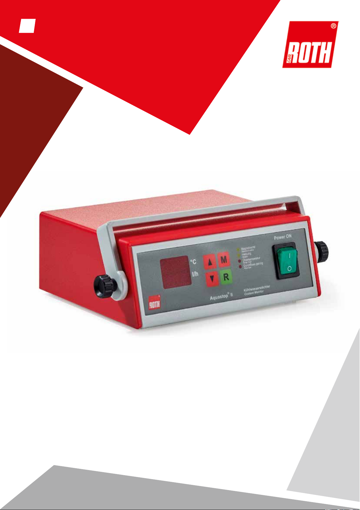
During normal operation, AQUASTOP®II works in surveillance mode. The actual temperature of the
cooling water is shown in the upper part of the display. If an external temperature sensor is used
(which automatically disconnects the internal temperature gauge in the ow sensor), make sure that
this sensor is located at an appropriate position to measure the critical temperature in the process.
The measured cooling water ow in liter per minute is shown in the lower part of the display.
If the actual temperature approaches the programmed limit value (see chapter 7.1), a pre-alarm
sounds if the tolerance (see chapter 7.3) is reached. The red LED „High temperature“ ashes and
an acoustical alarm sounds at the same time.
If the limit temperature is reached, the heating load is denitely switched o (yellow LED „Heating“
is extinguished), the red LED „Temp high“ lights continuously and the oating contact for external
alarm is activated. The temperature indication on the display ashes also, the solenoid cooling water
valve remains open to ensure the correct cooling of the installation.
The cooling water ow surveillance works in a similar manner: If the ow approaches the programmed
limit value (see chapter 7.2), a pre-alarm sounds if the tolerance value (see chapter 7.4) is reached.
The red LED „Flow low“ ashes, an acoustical alarm sounds at the same time. If the limit ow value
is reached, the heater as well as the solenoid valve are denitely switched o (yellow LEDs „Heating“
and „Solenoid valve“ are extinguished), the red LED „Flow low“ lights continuously and the oating
contact for external alarm is activated. The ow indication on the display ashes.
An acknowledgement of the pre-alarms is not necessary, as soon as the temperature or the water
ow are again outside the programmed tolerance range, the pre-alarm stops.
On the contrary, the nal alarm provokes a denite switching-o, which can only be recycled by
pressing the green „R“-key (6). This key causes a complete initialisation of the unit, shown by a
circling digit display indication. During 50 s, all alarms are inhibited, the heater as well as the
solenoid valve are switched on again. If the failure is not corrected (increased water ow or adjust
the alarm values), the alarms are re-engaged and act accordingly.

9
5
INSTALLATION AND WIRING
5.1 Installation
The installation site must provide easy access for the operator without hazard. Sucient mechanical
stability must be guaranteed, also secure the device from slipping on the installation surface.
To ease operation and good visibility of the display, the handle can be used as a support.
To adjust the position of the handle, unfasten the screws on both sides of the handle and fasten
them again after adjustment.
5.2 Wiring of power supply
Before wiring the device, make sure that the main switch is in position OFF „0“. Herewith, all poles
are disconnected from the mains voltage. Before working on the device itself or on an installation
connected to it, the unit must be prevented against unintentional restart. This can be done by
retracting the power cable and securing it against re-connecting.
After having nished the wiring completely, switch the device on with main switch in position ON „1“.
5.3 Wiring of accessories
Pin assignment of ow meter with
integrated temperature sensor
Pin assignment of the external (alternative)
Pt100 temperature sensor
Pin assignment of the alarm
connector

10
5.3 Wiring of accessories
Fig.: Back AQUASTOP
®II
5INSTALLATION AND WIRING
1External Pt100 temperature
2Flowmeter
3Floating alarm contact max. 230 V / 1 A
4Serial interface RS-232
5Fuse heating 16 A MT
6Fuse solenoid valve 0,5 A MT
7Fuse controller 0,2 A MT
8Power cord
9Socket solenoid valve 230 V
10 Socket heating 230 V, 16 A
1
2
3
45
910
678

11
6.1 Operating elements and keys
Fig.: Front AQUASTOP® II
6
OPERATION
1Multi-function display
2„UP“-key
3„Mode“-key
4LED signalisation operational state
5Main switch
6„Reset“-key
7„DOWN“-key
1 2 3 4
567

12
Key operational functions:
LED signalisation:
6.1 Operating elements and keys
Press the UP or DOWN keys (2/7) to increase or decrease the actual value by 1 digit.
Illuminated when solenoid valve is engaged.
Illuminated when heating is on.
Move up or down quickly by holding the key pressed.
MODE-key, toggles the display from actual value to program mode.
Set the duration of the pre-alarm by pressing both „M“ (3) and „UP“ or
„DOWN“-keys (2/7) simultaneously.
Flashes if temperature approaches the programmed limit value,
illuminated if limit value is reached.
Flashes if coolant ow approaches the programmed limit value,
illuminated if limit value is reached.
RESET (6) the surveillance algorithm to initial position. The unit then behaves as after
an complete restart (Power ON).
6OPERATION
Magnetventil
Solenoid valve
Heizung
Heater
Übertemperatur
Temp high
Durchuss gering
Flow low

13
6.2 Start-up
Attention:
Before switching the unit on, make sure that all tubing is tightly secured and the ow meter is mounted
in the right direction of the cooling water stream (see arrow).
After verication of all electrical connections, switch the coolant monitor on (5). The green light within
the main power switch is now illuminated.
Open then the water tap and adjust the water ow to the desired ow value shown on the lower line
of the display (1). During 50 s after the initial start-up (or after having pressed the RESET-key (6),
AQUASTOP® II is re-initialized and all alarms are inhibited. This gives you enough time to ll
and adjust the entire installation.
During this period, a circling digit on the display shows the initialisation phase. Occasional alarms are
only indicated by ashing of the corresponding LED (4), but do not inuence the connected heating
and/or solenoid valve.
6
OPERATION

14
To alter the temperature limit value, press once the „M“-key (3). On the lower line of the display, „te“
is shown and the temperature limit value shown on the upper display line can now be altered with
the „UP / DOWN“ keys (2/7). Maintaining the keys pressed makes increasing or decreasing the
value quicker. The new limit value is automatically accepted after 20 s (back to surveillance mode).
Pressing the „M“-key (3) again switches over to the next menu parameter.
On the upper line of the display, „o“ is shown and the ow limit value shown on the lower display line
can now be altered with the „UP/DOWN» keys (2/7). Maintaining the keys pressed makes increasing
or decreasing the value quicker. The new limit value is automatically accepted after 20 s
(back to surveillance mode). Pressing the „M“-key (3) again switches back to surveillance mode.
7SETTING THE OPERATIONAL LIMIT VALUES
7.1 Temperature limit value
7.2 Flow limit value

15
Starting from the normal surveillance mode, press and maintain the „UP“-key (2), then press
additionally the „M“-key (3). On the lower line of the display, „tol“ is shown and the temperature
tolerance value shown on the upper display line can now be altered with the „UP/DOWN“ keys (2/7).
This tolerance value determines the temperature dierence from the programmed limit value
(see chapter 7.1), at which the acoustical pre-alarm sounds. The new tolerance value is
automatically accepted after 20 s or after having pressed the „M“-key (3). The unit then switches
back to surveillance mode.
Starting from the normal surveillance mode, press and maintain the „DOWN“-key (7),
then press additionally the „M“-key (3). On the upper line of the display, „tol“ is shown and the ow
tolerance value shown on the lower display line can now be altered with the „UP/DOWN“ keys (2/7).
This tolerance value determines the ow dierence from the programmed limit value (see chapter 7.2),
at which the acoustical pre-alarm sounds. The new limit value is automatically accepted after 20 s
(back to surveillance mode). Pressing the „M“-key (3) again switches over to the next menu parameter.
7
SETTING THE OPERATIONAL LIMIT VALUES
7.3 Temperature tolerance value
7.4 Flow tolerance value

16
If AQUASTOP
® II is delivered together with a ow meter, the unit is already adjusted with that sensor
and no extra calibration is required. In case of replacement of a ow meter, a new calibration of the
unit to that other sensor is needed.
Therefor, install an additional calibrated owmeter in the cooling water circuit downstream of the
sensor to be calibrated and adjust a water ow of 90 l/min.
Starting from the normal surveillance mode, press and maintain the „DOWN“-key (7), then press
additionally the „M“-key (3) once. Release then the „DOWN“-key (7) and press again the „M“-key (3).
In the upper display line, the calibration factor is shown, in the lower line, the word „CAL“ is shown
alternating with the actual ow value. With the „UP / DOWN“-keys (2/7), you can now alter the
calibration factor in 0,01 steps within a range from 0,1 up to 9,99. Modify the calibration factor until
the actual ow value shown in the lower display line matches the ow value measured with the
additional ow meter mounted downstream of the new sensor.
The new calibration factor is conrmed by pressing the „M“-key (3). If no conrmation takes place,
the unit switches automatically back to normal surveillance mode by using the former calibration factor.
7SETTING THE OPERATIONAL LIMIT VALUES
7.5 Calibration of the flow meter

17
8
ERROR MESSAGES
8.1 Temperature sensor failure
8.2 Flow meter failure
No signal on the temperature sensor entrance:
•Check the sensor connector
•Check the electrical wiring (might be damaged)
Wrong signal on the ow sensor entrance:
•Purge the exible hosing (air bubbles might cause an irritation of the sensor)
•Check the owmeter for contamination
•Check the ow (ow > 100 l/h situated out of the range of the owmeter)

18
9SERIAL INTERFACE
Pin assignment of the connector
Transmission parameters
To be set in accordance with the host computer.
Protocol: 9.600 baud
8 bit
No parity
1 stop bit
1DCD
2RxD
3TxD
4DTR
5GND
6DSR
7RTS
8CTS
9RING
One line is sent every second, nished by ‘Return’ (CR) and ‘Linefeed (LF)’.
6 values ASCII are being sent, separated by comma:
•Flow real value (3 digits, starting with zero)
•Temperature real value (3 digits, starting with zero)
•Temperature pre-alarm active (binary 0 / 1)
•Temperature main alarm active (binary 0 / 1)
•Flow pre-alarm active (binary 0 / 1)
•Flow main alarm active (binary 0 / 1)
In case of void values, the ASCII-signs «---» are sent at the place of the corresponding value.

19
11
CE-CONFORMITY CERTIFICATE
DECLARATION OF CONFORMITY
This declaration is valid for the following products:
Model designation: Coolant monitor
Type: AQUASTOP
®
II
Hereby is conrmed, that these products meet in their design and accomplishment
as marketed by the manufacturer and if properly used the following EU-directives:
EU-Low voltage directive 2004/108/EG
EU-Directive for electromagnetic compatibility 2006/95/EG
Applicable harmonized norms: EN 60204 Part 1
EN 61000-6-1
EN 61000-6-3
This declaration is binding for the manufacturer
NOLDEN REGELSYSTEME GMBH
Am Tonschuppen 2 · Gewerbegebiet Volmershoven
D-53347 Alfter · Germany
Alfter, 01.01.2015 Hans Werner Müller,
General manager

Global Contact:
Carl Roth GmbH + Co. KG · Schoemperlenstr. 3-5 · 76185 Karlsruhe · Germany
Phone: +49 (0)721/5606-0 · Fax: +49 (0)721/5606-149
info@carlroth.de · www.carlroth.com
All supplies and deliveries are subject to the terms and conditions of sale and delivery of
Carl Roth GmbH + Co. KG, Karlsruhe.
Other manuals for AQUASTOP II
1
This manual suits for next models
1
Table of contents
Other Roth Laboratory Equipment manuals
Popular Laboratory Equipment manuals by other brands

Codonics
Codonics Horizon SF manual

Sonel
Sonel KT-560 user manual

Heraeus
Heraeus Electro-Nite CasTemp Wireless Instructions and operating manual

BANDELIN
BANDELIN SONOREX DIGITEC-RC Instructions for use

Thermo Scientific
Thermo Scientific Cryo 740 Series Installation

Magnaflux
Magnaflux CSV Series Operation manual