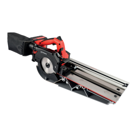
Rothenberger ROWELD BS 450 User manual

www.rothenberger.com
ROWELD BS 450
ROWELD BS 450
5.5603
Bedienungsanleitung
Instructions for use

Overview
A
1 2
3
4
5
6
7
8
9
10
11
12
13
15
16
17
18
14
X

Intro
CE-KONFORMITÄTSERKLÄRUNG
Wir erklären in alleiniger Verantwortung, dass
dieses Produkt mit den angegebenen Normen
und Richtlinien übereinstimmt.
EC-DECLARATION OF CONFORMITY
We declare on our sole accountability that this
product conforms to the standards and guidelines
stated.
2004/108/EG, 2006/42/EG, 2006/95/EG,
EN 60204-1, EN ISO 12100-1, EN ISO 12100-2
EN 50082-2, EN ISO 13850, EN ISO 13857
ppa. Arnd Greding Kelkheim, 28.10.2010
Head of R&D
Technical file at:
ROTHENBERGER Werkzeuge GmbH
Spessartstraße 2-4, D-65779 Kelkheim/Germany
1
DEUTSCH - Originalbetriebsanleitung!
ENGLISH
Bedienungsanleitung bitte lesen und aufbewahren! Nicht wegwerfen!
Bei Schäden durch Bedienungsfehler erlischt die Garantie! Technische Änderungen vorbehalten!
Please read and retain these directions for use. Do not throw them away! The warranty does not cover
damage caused by incorrect use of the equipment! Subject to technical modifications!
Seite 2
page 9

2 DEUTSCH
Inhalt Seite
1. Vorbemerkungen 3
2. Garantieregelungen 3
3. Bestimmungsgemäße Verwendung 4
4 Verpackung, Transport 4
5. Übersicht A 4
6. Technische Daten 5
7. Sicherheitsvorkehrungen 5
8. Inbetriebnahme 5
8.1 Aufstellung 5
8.2 Arbeiten durch den Elektriker 6
8.3 Arbeitsplatz / zugelassene Bediener 6
8.4 Erstinbetriebnahme 6
9. Bedienung 6
9.1 Sicherheitsvorschriften 6
9.2 Anforderungen an das ausführende Personal 6
9.3 Rohrspannung 7
9.4 Ein -und Ausschalten 7
9.5 Sägevorgang 7
9.6 Gehrungsschnitte 7
9.7 Sägebandspannung, korrekter Bandlauf 7
9.8 Sägebandwechsel 8
10. Ausschalten 8
11. Pflege und Wartung 8
12. Hilfe bei Störungen 9
13. Entsorgung 9
Kennzeichnungen in diesem Dokument
Gefahr
Dieses Zeichen warnt vor Personenschäden.
Achtung
Dieses Zeichen warnt vor Sach- oder Umweltschäden.
Aufforderung zu Handlungen

DEUTSCH
3
1. Vorbemerkungen
Diese Bedienungsanleitung ist Bestandteil des Lieferumfangs.
Sie ist in Zugriffsnähe bereitzuhalten und bleibt auch bei Verkauf der Maschine bei der Maschine.
Lesen Sie die Bedienungsanleitung komplett bevor Sie die Maschine benutzen.
Änderungen durch technische Weiterentwicklung gegenüber den in dieser Bedienungsanleitung
genannten Daten und Abbildungen behalten wir uns vor.
Nachdrucke. Übersetzungen und Vervielfältigungen in jeglicher Form, auch auszugsweise,
bedürfen der schriftlichen Zustimmung des Herausgebers.
Diese Bedienungsanleitung unterliegt keinem Änderungsdienst.
Den jeweiligen aktuellen Stand erfahren Sie bei:
ROTHENBERGER Werkzeuge GmbH, Industriestraße 7, D-65779 Kelkheim
Hinweise des Herstellers für den Benutzer:
Die Bandsägemaschine BS 450 entspricht in Technik, Funktion, und Handhabung dem Stand der
Technik und den grundlegenden Sicherheitsanforderungen gemäß EG-Richtlinien.
Hinweise für den Betreiber:
Als Betreiber sind Sie für die Einhaltung aller Sicherheitshinweise sowie den
bestimmungsgemäßen Gebrauch der Maschine verantwortlich.
Sorgen Sie dafür, daß jeder Bediener in die Handhabung der Maschine eingewiesen ist, und die
Maschine gefahrlos bedienen kann.
Richtlinien, Gesetze, Normen:
Bei der Konzeption und beim Bau der Sägemaschine wurden Inhalte und Hinweise aus
folgenden Richtlinien und Regelwerke beachtet:
Niederspannungsrichtlinie
EMV-Richtlinie
DIN EN 292
BGV A3 Elektrische Betriebsmittel
ABV Arbeitsmittelbenutzungsverordnung
2. Garantieregelungen
Grundsätzlich gelten unsere – Allgemeinen Verkaufs- und Lieferbedingungen.
Diese stehen dem Betreiber spätestens seit Vertragsabschluß zur Verfügung. Gewährleistungs-
und Haftungsansprüche bei Personen- und Sachschäden sind ausgeschlossen, wenn sie auf eine
oder mehrere der folgenden Ursachen zurückzuführen sind:
Nicht bestimmungsgemäße Verwendung der Maschine;
Unsachgemäßes montieren, inbetriebnehmen, bedienen und warten der Maschine;
Betreiben der Maschine bei defekten Sicherheitseinrichtungen oder nicht ordnungsgemäß
angebrachten Sicherheits- und Schutzvorrichtungen;
Nicht beachten der Hinweise in der Betriebsanleitung bezüglich Transport, Lagerung,
Montage, Inbetriebnahme, Betrieb, Wartung und Rüsten der Maschine;
Eigenmächtige bauliche Veränderungen an der Maschine;
Mangelhafte Überwachung von Maschinenteilen, die einem Verschleiß unterliegen;
Unsachgemäß durchgeführte Reparatur;
Fremdkörpereinwirkung und Höhere Gewalt.
4 DEUTSCH
3. Bestimmungsgemäße Verwendung
Die Bandsägemaschine Typ BS 450 dient ausschließlich zum Sägen von Kunststoffrohren und
Profilen aus Kunststoff.
Zur bestimmungsgemäßen Verwendung gehört auch das Lesen dieser Betriebsanleitung sowie das
Einhalten aller darin enthaltenen Hinweise – insbesondere der Sicherheitshinweise. Ferner gehört
dazu, daß auch alle Inspektions- und Wartungsarbeiten in den vorgeschriebenen Zeitintervallen
durchgeführt werden.
Die im Abschnitt “Technische Daten” dieses Kapitels angegebenen zulässigen Abmessungen für
das zu verarbeitende Material, sowie die anderen technischen Spezifikationen müssen
ausnahmslos eingehalten werden.
GEFAHR! Wird die Bandsägemaschine Typ BS 450 nicht bestimmungsgemäß
verwendet, so ist kein sicherer Betrieb der Maschine gewährleistet.
GEFAHR! Für alle Personen- und Sachschäden, die aus nicht
bestimmungsgemäßer Verwendung entstehen, ist nicht der Hersteller, sondern
der Betreiber der Bandsägemaschine verantwortlich.
4 Verpackung, Transport
Die Maschine wird auf einen Palettenboden gestellt und mit Folie verpackt. Für Seefracht wird die
Maschine in eine Kiste verpackt.
Transportsicherung:
Um ein unkontrolliertes Hochgehen oder Schwenken des Sägebügels während des Transports zu
vermeiden, ist der Sägearm am Maschinenständer mit einer Transportsicherung gesichert.
ACHTUNG! Beim Weitertransport der Säge muss der Sägebügel mit der
Transportsicherung am Maschinenständer befestigt werden!
Transportart:
Stapler oder Hubwagen (Anschlagpunkte Xsiehe Abb. A)
ACHTUNG! Maschine nicht am Sägebügel aufhängen!
5. Übersicht A
1 Hauptschalter 10 Anschluss-Stutzen für Absaugung
2 Schaltkasten mit Schütz und
Motorschutzschalter 11 Ausgleichsfeder
3 Sägebügel 12 Maschinenrahmen
4
Sägebandumlenkung mit
Schutzabdeckung für kleinere
Durchmesser
13 Tippschalter ( Auf der Rückseite des
Handgriffs )
5 Sterngriff zur Bandspannung 14 Feststellschraube Rohrspannung
6 Sterngriff zur Arretierung der
Bandspannung 15 Handrad
7 Prismenbett 16 Spannprisma
8 Anschlußkabel 17 Arretierungshebel für
Winkeleinstellung
9 Antriebsmotor 18 Winkelskala

DEUTSCH
5
6. Technische Daten
Allgemeine Daten:
Maschine L X B X H ...........................1200 X 1400 X 1800 mm
Gewicht ............................................160 kg
Bandabmessungen ............................3590 X 10 X 0,65 mm
Durchmesser Absaugstutzen .............Außen 76 mm, Innen 65 mm
Max. Rohrdurchmesser......................450 mm
Stromversorgung:
Spannung .........................................3N-PE-AC 400V
Nennstrom........................................2 A
Sicherung in der Zuleitung.................max. 16 A
Länge des Anschlußkabels.................3000 mm
Antriebsmotor...................................1,25 kW, 50 / 60 Hz
Sägeband:
Abmessungen ...................................3570 X 10 X 0,6 mm
Qualität.............................................Schmelzschnitt
7. Sicherheitsvorkehrungen
Sicherheitseinrichtungen sind zum Schutz des Betreibers der Maschine vorgeschrieben und dürfen
unter keinen Umständen entfernt werden, wenn die Maschine in Betrieb ist.
Die Sägemaschine dient ausschließlich zum Sägen von Kunststoffen!
Lesen Sie die Bedienungsanleitung sorgfältig durch und machen Sie sich mit den Sicherheits-,
Montage-, Bedienungs- und Wartungsanweisungen vertraut.
Schalten Sie die Maschine nicht ein, bevor alle Schutzvorrichtungen an Ihrem Platz sind.
Messungen am zu sägenden Material nur bei ausgeschalteter Säge vornehmen.
Vor Reparaturarbeiten muss die Sägemaschine vom Stromnetz getrennt werden.
Reparaturen dürfen nur von einem Fachmann ausgeführt werden.
Zur eigenen Sicherheit und zur Gewährleistung, dass die Maschine einwandfrei arbeitet,
sollten nur Original - Ersatzteile verwendet werden.
Reinigen Sie die Maschine regelmäßig!
Tragen Sie eine Schutzbrille!
Tragen Sie Handschuhe beim Sägebandwechsel!
Maschine nicht im Freien aufstellen.
8. Inbetriebnahme
8.1 Aufstellung
Die Säge auf einem ebenen Maschinenfundament aufstellen.
Mit der Wasserwaage nach beiden Richtungen justieren.
Transportart: Stapler oder Hubwagen (Anschlagpunkte Xsiehe Abb. A)
Verwenden Sie zur Vermeidung von Transportschäden nur ein Fördermittel mit ausreichender
Tragfähigkeit (mind. 500 kg).

6 DEUTSCH
Maschine nur in trockenen Räumen, niemals im Freien aufstellen!
Maschine an Absaugung anschließen
8.2 Arbeiten durch den Elektriker
Prüfen Sie, ob die Netzspannung mit der auf dem Typenschild angegebenen übereinstimmt.
Entsprechende Vorsicherung in Bezug auf die Leistung durchführen. Anschluss mit Kabel ( 5 X
2,5 mm2) über für Ihr System passenden Stecker der Maschine.
Prüfen Sie, ob die Drehrichtung stimmt (Pfeil auf Sägebandscheibe bzw. Pfeil auf
Sägeblattschutz), wenn nicht, Anschluss L1 und L2 vertauschen.
8.3 Arbeitsplatz / zugelassene Bediener
Der Arbeitsplatz muss sauber und gut ausgeleuchtet sein besonders auf Baustellen.
Nur geschultes Personal darf daran arbeiten. Das Mindestalter für Bediener beträgt 16 Jahre!
Der Bediener ist im Arbeitsbereich Dritten gegenüber verantwortlich.
Der Betreiber muss
dem Bediener die Betriebsanleitung zugänglich machen und
sich vergewissern, dass dieser sie gelesen hat und versteht.
8.4 Erstinbetriebnahme
Transportsicherung entfernen und 2. Zugfeder wieder einhängen.
ACHTUNG! Beim Entfernen der Transportsicherung kann der Bügel nach hinten kippen,
Quetschgefahr!
Grundeinstellungen vornehmen, Sägeband auflegen und Spannvorrichtung einsetzen.
Rohstoffe (Rohre) für Produktionstest vorbereiten.
Funktionsprüfung und Kontrollen nach Checkliste:
Energieversorgung
Sicherheitseinrichtungen
Bügel in Ausgangsstellung hinten
Drehrichtung Motor
Richtige Spannung des Sägebandes.
9. Bedienung
9.1 Sicherheitsvorschriften
Achten Sie vor Inbetriebnahmen, dass sich keine umstehenden Personen im
Gefahrenbereich befinden!
Bestimmungsgemäße Verwendung (Pkt. 3) beachten!
9.2 Anforderungen an das ausführende Personal
An der Maschine darf nur eingewiesenes Personal arbeiten!

DEUTSCH
7
9.3 Rohrspannung
Sägebügel in hintere Ausgangsstellung bringen.
Rohr auflegen und mittels Gewindespindel mit Spannprisma und Handrad spannen, bis es
sich nicht mehr drehen lässt. Lange Rohre über Rollenbock abstützen!
Rohre oder andere Werkstücke sind immer einzuspannen!
9.4 Ein -und Ausschalten
Hauptschalter am Schaltkasten einschalten.
Durch Drücken des Tasters auf der Rückseite am Handgriff schaltet sich das Sägeband ein. Der
Taster muss während des ganzen Sägevorgangs gedrückt sein.
SCHWERSTE VERLETZUNGSGEFAHR! Die freie Hand nicht in den Gefahrenbereich
des Sägebandes bringen!
9.5 Sägevorgang
Sägebügel ausgeschaltet in hintere Ausgangsposition bringen.
Winkeleinstellung auf gewünschte Gradzahl stellen und festziehen.
Rohr auflegen, in die gewünschte Position bringen und mit dem Spannprisma befestigen.
Sägebandabdeckung nur in Querschnittgröße der Werkstücke öffnen!
Sägeband mittels Taster einschalten und langsam nach vorne ziehen.
Maschine und Sägeband nicht durch zu hohen Vorschub belasten!
Um einen sauberen Sägeschnitt, vor allem bei Winkelschnitten zu erhalten, ist darauf zu achten,
dass das Rohr langsam angeschnitten wird.
Nur scharfe Sägebänder benutzen!
9.6 Gehrungsschnitte
Die Säge ist so ausgelegt, dass an Rohren bis Durchmesser 450 mm Gehrungsschnitte von 0° -
45° nach einer Seiten gemacht werden können.
Lösen Sie nun den Klemmhebel an der Winkelskala zur Arretierung des Sägebügels und
schwenken Sie diesen auf die gewünschte Gradzahl.
Ist diese eingestellt, so fixieren Sie den Sägebügel mit dem Klemmhebel
Die Winkeleinstellung darf nur bei ausgeschalteter Säge vorgenommen werden!
9.7 Sägebandspannung, korrekter Bandlauf
Um winkelige Abschnitte sowie eine gute Schnittleistung durch die Sägemaschine zu erhalten, ist
die richtige Bandspannung von entsprechender Bedeutung.
Das Band ist richtig gespannt, wenn der Markierungsstrich an der Führung des Spannrades mit
der „MAX“ Markierung übereinstimmt.
Ist das Band zu wenig gespannt, springt es aus der Bandumlenkung.
VERLETZUNGSGEFAHR ! !

8 DEUTSCH
Das Sägeband muss mittig auf den Rädern laufen. Die Räder sind ballig gedreht, sodass die Zähne
frei laufen.
Sollte das Sägeband von den Rädern ablaufen, kann das Spannrad mittels Einstellschraube 22
eingestellt und mit Sterngriff 6arretiert werden
9.8 Sägebandwechsel
Arbeitshandschuhe anziehen.
Maschine ausschalten , Hauptschalter auf AUS.
Deckel des Sägebügel durch Lösen der Schrauben öffnen.
Rollenarretierung über den Sterngriff (6) lösen.
Band durch Linksdrehen des Sterngriffs (5) entlasten, aus den Bandumlenkungen ziehen und
abnehmen.
Neues Band auflegen, Zähne müssen nach hinten und in Schneidrichtung zeigen.
Band in Bandumlenkung einführen und durch Rechtsdrehen des Sterngriffs spannen bis der
Zeiger auf der Rückseite mit der MAX – Markierung übereinstimmt.
Durch Drehen der Räder von Hand in Schnittrichtung auf richtigen Sitz des Bandes achten.
Deckel des Sägebügels wieder anbringen.
Warnung! Beim Auseinanderdrehen von neuen Bändern besteht die Gefahr, dass
sie aufschnellen und Verletzungen vor allem im Gesicht herbeiführen!
10. Ausschalten
Für kurze Betriebsunterbrechungen Hauptschalter ausschalten
Für längere Betriebsunterbrechungen ( z.B. über Nacht, übers Wochenende oder in der
Urlaubsperiode ) Hauptschalter ausschalten und abschließen.
11. Pflege und Wartung
Täglich
Sägebandräder, Bandumlenkung und die Umgebung des Sägebandes von Spänen reinigen.
Abstreifbürste reinigen
Wöchentlich
Säge gründlich reinigen, Gelenke schmieren, blanke Maschinenteile einölen.
Jährlich
Sämtliche Sicherheitseinrichtungen und elektrische Teile auf Funktion prüfen.
Gesetzliche Sicherheitsprüfungen durchführen
22 5
6

DEUTSCH
9
12. Hilfe bei Störungen
Störung Mögliche Ursache Zu beheben durch Benutzer
Motor läuft nicht Stecker nicht eingesteckt ja
Kabel defekt nein
Motorschutzschalter defekt nein
Sägeband springt ab Räder verschmutzt ja
Sägebandspannung stimmt nicht ja
Bandumlenkung verschmutzt ja
Falsche Radeinstellung ja
13. Entsorgung
Späne, Kunststoffabfälle und verschlissene Sägebänder müssen einer fachgerechten Entsorgung
zugeführt werden.

10 ENGLISH
Contents Page
1. Preliminary remarks 11
2. Guarantee regulations 11
3. Intended use 12
4 Package, Transport 12
5. Overview A 12
6. Technical Data 12
7. Safety precautions 13
8. Start up 13
8.1 Installation 13
8.2 Work to be done by an electrician person 14
8.3 Workplace / licensed operator 14
8.4 Initial operation 14
9. Operating 14
9.1 Safety regulations 14
9.2 Notes for the operator 14
9.3 Tube clamping 14
9.4 Switching on and off 15
9.5 Operating process 15
9.6 Mitre cuts 15
9.7 Saw band tensioning, correct band run 15
9.8 Changing the saw band 16
10. Switching off 16
11. Care and maintenance 16
12. Troubleshooting 16
13. Disposal 16
Markings in this document
Danger
This sign warns against the danger of personal injuries.
Caution
This sign warns against the danger of property damage and damage to the
environment.
Call for action

ENGLISH
11
1. Preliminary remarks
These operating instructions are part of the scope of delivery.
They are to be held ready in access proximity and must remain with the machine also in case of
sale of the machine. Please read this operating manual complete before using the machine.
Changes due to technical progress regarding the data and figures contained in these operating
instructions are reserved.
Reprint, translation, and duplication in any form, also in part, require the written consent of the
publisher.
These operating instructions are not subject to an updating service.
You can inquire about to the respective current state at:
ROTHENBERGER Werkzeuge GmbH, Industriestraße 7, D-65779 Kelkheim
Notes from the manufacturer for the user:
The band saw machine BS 450 corresponds to the current state of the art in technology, function,
and operability and conforms to the fundamental safety requirements in accordance with EEC
guidelines.
Notes for the operator:
As operator, you are responsible for the adherence to all safety instructions and for the intended
use of the machine.
Make sure that each user masters the handling of the machine and can safely operate the
machine.
Guidelines, laws, standards:
In the conception and building of the plastic sawing machine, contents and instructions from the
following guidelines and regulations have been observed:
Low-voltage guideline
EMV- guideline
DIN EN 292
BGV A3 Electrical equipment
ABV Working material usage regulations
2. Guarantee regulations
In principle, our – General Terms of Sales and Delivery – apply.
These are put at the operator's disposal with the conclusion of the contract at the latest.
Guarantee and liability claims for damages to property and persons are excluded if they are based
on one or several of the following causes:
not intended use of the machine;
inappropriate assembly, starting-up, operating, and maintenance of the machine;
operation of the machine with defective safety devices or not duly attached safety and
protection devices;
non-observance of the instructions in the manual concerning transport, storage, assembly,
start-up, operation, maintenance, and preparation of the machine;
arbitrary structural changes to the machine;
flawed monitoring of machine parts that are subject to wear;
inappropriately performed repair;
influence of foreign objects and acts of God.

12 ENGLISH
3. Intended use
The band saw machine type BS 450 is intended exclusively for the sawing of plastic tubes.
The intended use also includes reading this manual as well as adherence to all instructions
contained in it – in particular the safety instructions. Furthermore, it also includes that all
inspection and maintenance work is accomplished within the prescribed time intervals.
The permissible dimensions for the material to be processed, as well as the other technical
pecifications indicated in the section "Technical data" of this chapter, must be observed without
exception.
DANGER! If the band saw machine type BS 450 is not used in accordance with
this regulation, then no safe operation of the machine is ensured.
DANGER! For all damages to property and persons that result from not intended
use, not the manufacturer but the operator of the band saw is responsible.
4 Package, Transport
The machine is placed on a pallet base and wrapped with foil. For sea freight, the machine is
packed in a box.
Transport lock:
To avoid uncontrolled moving or swinging the saw arm in transport, the saw bow is secured to
the machine stand with a transport lock.
ATTENTION! By further transport of the saw, the saw bow is secured to the machine
stand with the transport lock!
Transport type:
Lift truck or elevating truck (Guide positons X see fig. A)
ATTENTION! Do not hung up the machine by the saw bow !
5. Overview A
1 Main switch 10 Connection vacuum cleaner
2 Switch board 11 Compensation spring
3 Saw bow 12 Main frame
4 Saw band deflection with protection
for smaller diameters 13 Start button (at the back side of the
hand grip)
5 Grip for band tensioning 14 Fixing screw
6 Grip to fix the band tensioning 15 Hand wheel
7 Table 16 Clamping prism
8 Motor cable 17 Fixing of the angle scale
9 Main motor 18 Angle scale
6. Technical Data
General data:
Machine L X W X H ...........................1200 X 1400 X 1800 mm
Weight..............................................160 kg
Saw band dimensions........................3590 X 10 X 0,65 mm
Diameter connecting piece ................Outer 76 mm, Inner 65 mm

ENGLISH
13
Max. pipe diameter ...........................450 mm
Electrical data:
Voltage .............................................3N-PE-AC 400V
Nominal current ................................2 A
Fuse (supply line)...............................max. 16 A
Lenght of cable connection ...............3000 mm
Motor ...............................................1,25 kW, 50 / 60 Hz
Saw band:
Dimensions .......................................3570 X 10 X 0,6 mm
Quality ..............................................Fusion cut
7. Safety precautions
Safety devices are prescribed for the protection of the operator of the band saw machine and
must not be removed under any circumstances while the machine is in operation.
The sawing machine is intended exclusively for sawing plastics!
Carefully read the operating instructions and make you acquainted with the security,
assembly, operating, and service instructions.
Do not switch on the machine before all protection devices are in place.
Measurements at the material to be sawed must only be performed when the saw is switched
off.
Prior to any maintenance or repair work, the sawing machine must be electrically separated
from mains.
Repairs may only be performed by a specialist.
For your own security and to ensure that the machine works perfectly, only original spare
parts should be used.
Clean the machine regularly!
Wear eye protectors during all kind of work at the machine!
Wear gloves when changing the saw band!
Do not install the Machine in the open.
8. Start up
8.1 Installation
Install the band saw machine on a flat machine foundation.
Adjust with the special spirit level for machines in both directions the main frame of the
machine.
Mode of transport: Lift truck or elevating truck (Attachment points Xsee fig. A)
Use to prevent damage in transit only one with sufficient funding capacity (min. 500 kg).
Machine only in dry areas, set up for indoor use!
Connect the machine to suction!

14 ENGLISH
8.2 Work to be done by an electrician person
Check whether the mains voltage agrees with the voltage indicated
on the rating plate.
Provide suitable perfuse with reference to the performance. Connection with cable (5 X 2,5
mm2H07 RN-F 4G 2,5) via a plug of the machine that is suitable for your system.
Check whether the direction of rotation is correct (arrow on saw band disk and / or arrow on
saw blade protection); if not, interchange connections L1 and L2.
8.3 Workplace / licensed operator
The area should be clean and well lit especially on construction sites.
Only trained personnel should work on it. The minimum age for operators is 16 years!
The operator is in the work area from third parties responsible.
The operator must:
the operator's manual be made available and
make sure that this has been read and understand.
8.4 Initial operation
Remove transport lock and hang up the 2.spring.
Attention! Until removing of transport lock the saw bow can be tilt back. Risc of
crushing!
Take on basic setting, fit on the saw band and install the clamping device.
Prepare the pipe for the production test.
Functional testing and inspections to check list:
Electrical power supply
Safety installations
Saw bow in starting position back
Motor reversing
correct band tension.
9. Operating
9.1 Safety regulations
Before starting the machine, verify and ensure that, nobody can be injured by
starting the machine!
Take note to intended use (sect. 3)!
9.2 Notes for the operator
Make sure that each user masters the handling of the machine and can safely operate the
machine!
9.3 Tube clamping
Saw bow bring back starting position.
Lay pipe and tighten the threaded spindle with clamping prism and hand wheel until it no
longer can be turned. Long tubes supported on roller block!
Tubes or other workpieces are harnessing increasingly!

ENGLISH
15
22 5
6
9.4 Switching on and off
Switch on the main switch on the control box.
By pressing the button on the back of the handle, the saw band switches on. The pushbutton
must held pressed during the complete sawing process.
HEAVIEST INJURY! The free hand can not get into the danger area of the saw
blade!
9.5 Operating process
Bring back switched off saw bow into original position.
Angle setting selector to the desired number of degrees and tighten.
Lay on the pipe, bring it in the desired position and secure with the chip prism.
Open saw band cover only in cross-sectional size of the workpieces!
Switch on saw band and und slowly pull forward.
Machine and saw band are not exposed to excessive feed!
To a well saw cut to obtain especially for mitre cuts is to make sure that the tube is slowly raised.
Only use sharp edged saw bands!
9.6 Mitre cuts
The saw is designed in such a way that at pipes up to diameter 450 mm, mitre cuts can be made
by 0° - 45° to one side.
loosen the clamp lever at the angular scale for locking the saw bow pivot and move it to the
desired number of degrees.
If this is set, fix the saw bow with the clamping lever.
The angle adjustment has only be done by switching off the machine!
9.7 Saw band tensioning, correct band run
In order to achieve angular cuts as well as a good cutting performance by the sawing machine,
correct band tension is of significant importance.
The band is correctly tensioned if the marker line on the leadership of the tension wheel with the
"MAX" mark conforms.
If the saw band has too low tension, it will jump out of the saw band deflection.
DANGER OF INJURY!!
The saw band must run
centrically on the wheels. The
wheels are spherically rotated, so
that the teeth run freely.
If the saw band escapes from the
wheels, adjust the tensioning
wheel with adjusting screw 22
and lock with star handle 6.

16 ENGLISH
9.8 Changing the saw band
Wear working gloves.
Switch off the machine, turn the main switch.
Remove wheel covers and saw band covers.
Release roller lock by star handle (6).
Relieve saw band by turning the star handle anti-clockwise, pull out of the saw band detours
and take off.
Insert new saw band; teeth must point to the rear and in cutting direction.
Introduce saw band into saw band deflection, and apply tension by turning the star handle
right.
Check proper fit of the saw band by turning the wheels by hand in cutting direction.
Re-attach wheel covers and saw band covers.
When rotating new saw bands apart, there is a risk that they might jump open
and cause injuries, particularly to the face!
10. Switching off
For short interruption of work switch off the machine by main switch.
For longer interruption of work ( e.g. over night, weekend or in holiday ) turn off main switch
and close.
11. Care and maintenance
Daily
Clean saw band wheels, saw band deflection, and the environment of the saw band of splinters
and dust. Clean wiper brusk.
weekly
Thoroughly clean saw, lubricate guides. Control the safety parts of the saw.
yearly
Check the saw band guiding system and check all the electric parts.
Statutory safety checks carried out
12. Troubleshooting
Trouble possible cause can be done by user
Motor doesn’t run Plug not inserted yes
Cablefailure no
Motor overload switch failure no
Saw band jump out wheels polluted yes
Saw ban tension isn’t correct yes
band redirection polluted yes
wheel adjustment isn’t correct yes
13. Disposal
The regulations for normal recycling of waste and/or removal are to be adhered. Pay attention to
environmentally friendly disposal of fuels, lubricants, and auxiliary materials.

17
NOTES

11.10/F&E
ROTHENBERGER Worldwide
ROTHENBERGER Werkzeuge Produktion GmbH
Lilienthalstraße 71 - 87 • D-37235 Hessisch-Lichtenau
Tel.+ 49 56 02 / 93 94 - 0 • Fax + 49 56 02 / 93 94 36
ROTHENBERGER Deutschland GmbH
Industriestraße 7 • D-65779 Kelkheim/Germany
Tel. + 49 61 95 / 800 3 13 • Fax + 49 61 95 / 800 365
verkauf-deutschland@rothenberger.com
ROTHENBERGER Australia Pty. Ltd.
Unit 12 • 5 Hudson Avenue • Castle Hill • N.S.W. 2154
Tel. + 61 2 / 98 99 75 77 • Fax + 61 2 / 98 99 76 77
rothenberger@rothenberger.com.au
www.rothenberger.com.au
ROTHENBERGER Werkzeuge- und Maschinen
Handelsgesellschaft m.b.H.
Gewerbeparkstraße 9 • A-5081 Anif near Salzburg
Tel. + 43 62 46 / 7 20 91-45 • Fax + 43 62 46 / 7 20 91-15
office@rothenberger.at • www.rothenberger.at
ROTHENBERGER Benelux bvba
Antwerpsesteenweg 59 • B-2630 Aartselaar
Tel. + 32 3 / 8 77 22 77 • Fax + 32 3 / 8 77 03 94
info@rothenberger.be • www.rothenberger.be
ROTHENBERGER do Brasil Ltda.
Rua marinho de Carvalho, No. 72 - Vila Marina
09921- 005 Diadema - Sao Paulo - Brazil
Tel. + 55 11 / 40 44 47-48 • Fax + 55 11 / 40 44 50-51
vendas@rothenberger.com.br • www.rothenberger.com.br
ROTHENBERGER Bulgaria GmbH
Boul. Sitniakovo 79 • BG-1111 Sofia
Tel. + 35 9 / 2 9 46 14 59 • Fax + 35 9 / 2 9 46 12 05
info@rothenberger.bg • www.rothenberger.bg
ROTHENBERGER Pipe Tool (Shanghai) Co., Ltd.
D-4, No.195 Qianpu Road,East New Area of Songjiang
Industrial Zone, Shanghai 201611, China
Tel. + 86 21 / 67 60 20 77 • + 86 21 / 67 60 20 61
Fax + 86 21 / 67 60 20 63 • office@rothenberger.cn
ROTHENBERGER CZ, náradí a stroje, spol. s.r.o.
Lnárská 907 / 12 • 104 00 Praha 10 - Uhríneves
Tel. +42 02 / 71 73 01 83 • Fax +42 02 / 71 73 01 87
info@rothenberger.cz • www.rothenberger.cz
ROTHENBERGER Scandinavia A/S
Fåborgvej 8 • DK-9220 Aalborg Øst
Tel. + 45 98 / 15 75 66 • Fax + 45 98 / 15 68 23
roscan@rothenberger.dk
ROTHENBERGER France S.A.
24, rue des Drapiers, BP 45033 • F-57071 Metz Cedex 3
Tel. + 33 3 / 87 74 92 92 • Fax + 33 3 / 87 74 94 03
info-fr@rothenberger.com
ROTHENBERGER Hellas S.A.
Agias Kyriakis 45 • 17564 Paleo Faliro • Greece
Tel. + 30 210 94 02 049 • +30 210 94 07 302 / 3
Fax + 30 210 / 94 07 322
ROTHENBERGER Hungary Kft.
Gubacsi út 26 • H-1097 Budapest
Tel. + 36 1 / 3 47 - 50 40 • Fax + 36 1 / 3 47 - 50 59
info@rothenberger.hu
ROTHENBERGER India Private Limited
B-1/D-5,Ground Floor
Mohan Cooperative Industrial Estate,
Mathura Road, New Delhi 110044
Tel. + 9111/ 41 69 90 40, 41 69 90 50 • Fax + 9111/ 41 69 90 30
ROTHENBERGER Ireland Ltd.
Shannon Industrial Estate
Shannon, Co. Clare
Tel. + 35 3 61 / 47 21 88 • Fax + 35 3 61 / 47 24 36
ROTHENBERGER Italiana s.r.l.
Via G. Reiss Romoli 17-19 • I- 20019 Settimo Milanese
Tel. + 39 02 / 33 50 601 • Fax + 39 02 / 33 50 0151
rothenberger@rothenberger.it • www.rothenberger.it
Australia
Austria
Belgium
Brazil
Bulgaria
China
Czech
Republic
Denmark
France
Greece
Hungary
India
Ireland
Italy
ROTHENBERGER Chile Limitada
Santo Domingo, 1160 Piso 11 • Oficina 1101
Santiago de Chile • Chile
Tel. + 56 241 791 30 • Fax + 56 253 964 00
ventas.chile@rothenberger.es
Chile
Germany
ROTHENBERGER Nederland bv
Postbus 45 • NL-5120 AA Rijen
Tel. + 31 1 61 / 29 35 79 • Fax + 31 1 61 / 29 39 08
info@rothenberger.nl • www.rothenberger.nl
ROTHENBERGER Polska Sp.z.o.o.
Ul. Annopol 4A • Budynek C • PL-03-236 Warszawa
Tel. + 48 22 / 2 13 59 00 • Fax + 48 22 / 2 13 59 01
biuro@rothenberger.pl • www.rothenberger.pl
SUPER-EGO TOOLS FERRAMENTAS, S.A.
Apartado 62 - 2894-909 Alcochete - PORTUGAL
Tel. + 351 91 / 930 64 00 • Fax + 351 21 / 234 03 94
sul.pt@rothenberger.es
ROTHENBERGER-TOOLS SA (PTY) Ltd.
P.O. Box 4360 • Edenvale 1610
165 Vanderbijl Street, Meadowdale Germiston
Gauteng (Johannesburg), South Africa
Tel. + 27 11 / 3 72 96 33 • Fax + 27 11 / 3 72 96 32
info@rothenberger-tools.co.za
ROTHENBERGER S.A.
Ctra. Durango-Elorrio, Km 2 • E-48220 Abadiano (Vizcaya)
(P.O. Box) 117 • E-48200 Durango (Vizcaya)
Tel. + 34 94 / 6 21 01 00 • Fax + 34 94 / 6 21 01 31
export@rothenberger.es • www.rothenberger.es
ROTHENBERGER (Schweiz) AG
Herostr. 9 • CH-8048 Zürich
Tel. +41 (0)44 435 30 30 • Fax 41 (0)44 401 06 08
info@rothenberger-werkzeuge.ch
ROTHENBERGER Tes. Alet ve Mak. San. Tic. Ltd. Sti
Poyraz Sok. No: 20/3 - Detay Is Merkezi
TR-34722 Kadiköy-Istanbul
Tel. +90 / 216 449 24 85 pbx • Fax +90 / 216 449 24 87
rothenberger@rothenberger.com.tr
ROTHENBERGER UK Limited
2, Kingsthorne Park, Henson Way,
Kettering • GB-Northants NN16 8PX
Tel. + 44 15 36 / 31 03 00 • Fax + 44 15 36 / 31 06 00
info@rothenberger.co.uk
ROTHENBERGER USA LLC
4455 Boeing Drive, USA - Rockford, IL 61 109
Tel. + 1 / 8 15 3 97 70 70 • Fax + 1 / 8 15 3 97 82 89
www.rothenberger-usa.com
ROTHENBERGER USA Inc.
Western Regional Office • 955 Monterey Pass Road
Monterey Park, CA 91754
Tel. + 13 23 / 2 68 13 81 • Fax + 13 23 / 26 04 97
ROTHENBERGER México S DE RL DE VC
Bosques de Duraznos No. 69-1101 Torre A
Bosques de las Lomas • México 11700 D.F. Miguel Hidalgo
Tel. + 52 55 / 35 42 37 62 • Fax + 52 55 / 55 31 56 34
ventas.mexico@rothenberger.es
Netherlands
Poland
Portugal
South Africa
Spain
Switzerland
Turkey
UK
USA
Mexico
ROTHENBERGER Middle East FZCO
PO Box 261190 • Jebel Ali Free Zone
Dubai, United Arab Emirates
Tel. +971 / 48 83 97 77 • Fax +971 / 48 83 97 57
office@rothenberger.ae
UAE
ROTHENBERGER Agency
ROTHENBERGER Russia
Avtosavodskaya str. 25
115280 Moscow, Russia
Tel. +7 495 / 792 59 44• Fax + 7 495 / 792 59 46
Russia
ROWALT Utilaje SRL
Str. 1 Mai, no.4
RO-075100 Otopeni-Bucuresti, Ilfov
Tel. +40 21 / 3 50 37 44 • +40 21 / 3 50 37 45
Fax +40 21 / 3 50 37 46
office@rothenberger-romania.ro
Romania
www.rothenberger.com
ROTHENBERGER Werkzeuge GmbH
Industriestraße 7
D- 65779 Kelkheim / Germany
Telefon + 49 (0) 61 95 / 800 - 1
Fax + 49 (0) 6195 / 800 - 3500
info@rothenberger.com
Table of contents
Languages:
Other Rothenberger Saw manuals

Rothenberger
Rothenberger ROWELD BS 630 Plus User manual

Rothenberger
Rothenberger PIPECUT mini User manual

Rothenberger
Rothenberger ROCUT UKS 160/355 User manual

Rothenberger
Rothenberger PIPECUT 170 User manual

Rothenberger
Rothenberger PIPECUT 220 U User manual

Rothenberger
Rothenberger ROWELD BS 630 M User manual