Western Innovator FHM2 SERIES User manual

1 B20352 ECN-12354 (0301)
Installation and Operating Instructions For
FULLY AUTOMATIC CHANGEOVER MANIFOLD
FHM2, FHM2HL, & FHM2HP SERIES
INTRODUCTION
Western manifold systems are cleaned, tested and prepared for the indicated gas service and are built
following National Fire Protection Association and Compressed Gas Association guidelines. The manifold
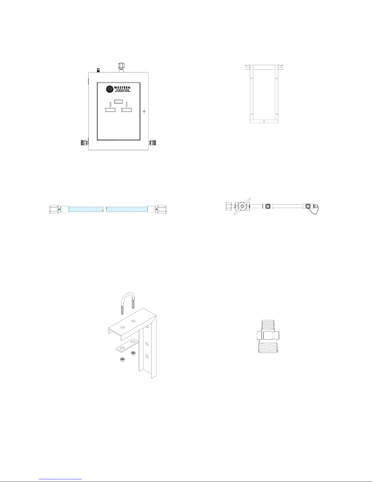
consists of a manifold control unit, an internal dual line assembly, and two supply bank headers, one service
and one secondary supply to provide an uninterrupted supply of gas for the specific gas application. The
manifold control unit is designed and built with features providing automatic changeover from the depleted
“Service” supply bank to the “Secondary” supply bank while maintaining a constant delivery pressure. Digital
pressure readouts, alarm, signal connections and lights show system status and alert the need to replace
depleted cylinders. Features of the automatic system include integral adjustable line regulators, power supply
with dry contacts for connecting to a remote alarm, stainless steel braided flexible pigtails with check valves,
rigid wall-mounted headers, and complete mounting hardware.
CAUTION
Failure to follow the subsequent instructions can result in personal injury or property damage:
• Never permit oil, grease, or any other combustible material to come in contact with cylinders, manifold,
and connections. Oil and grease may react and ignite while in contact with some gases-
particularly oxygen and nitrous oxide.
• Cylinder, header, and master valves should always be opened very s-l-o-w-l-y. Heat of recompression
may ignite combustible materials.
• Pigtails should never be kinked, twisted, or bent into a radius smaller than 3 inches. Mistreatment may
cause the pigtail to burst.
• Do not apply heat. Some materials may react and ignite while in contact with some gases–particularly
oxygen and nitrous oxide.
• Cylinders should always be secured with racks, chains, straps, or stands. Unrestrained cylinders may fall
over and damage, or break off the cylinder valve, which may propel the cylinder with great force.
• Oxygen manifolds and cylinders should be grounded. Static discharges and lightning may ignite materi-
als in an oxygen enriched atmosphere, creating a fire or explosion.
• Welding should not be performed near nitrous oxide piping. Excessive heat may cause the gas to
dissociate, creating an explosive force.
WARRANTY
All Western manifolds are warranted against defects in materials and workmanship for the period of one year
from date of purchase. See back cover for details of limited warranty.
LINE PRESSURE
LEFT BANK RIGHT BANK
SYSTEM NORMAL
WEST E RN I NNOVA T OR
875 B ASSE TT ROA D
WESTLAKE,OHIO44145
1-800- 783 -7 890
FHM2
FULLY A UTOMATIC HEALTH CARE G AS MANIFOLD
BANK DEPL ETED BANK DEPL ETED
READYFOR USE READYFOR USE
IN SERVI CEIN SERVI CE

2 B20352 ECN-12354 (0301)
TABLE OF CONTENTS
GENERAL INSTRUCTIONS...................................................................................................................................... 3
COMPONENTS ......................................................................................................................................................... 4
CONTROL SECTION INSTALLATION...................................................................................................................... 5
HEADER INSTALLATION ......................................................................................................................................... 6
CONNECTING TO THE DELIVERY PIPELINE ........................................................................................................ 7
RELIEF VALVE VENT LINE ...................................................................................................................................... 7
ELECTRICAL ............................................................................................................................................................. 8
REMOTE ALARM HOOKUP...................................................................................................................................... 9
INSTALLING PIGTAILS AND ATTACHING CYLINDERS ...................................................................................... 10
START UP AND SYSTEM CHECKING PROCEDURES ........................................................................................ 11
ELECTRICAL POWER UP ...................................................................................................................................... 12
LINE DELIVERY PRESSURE ADJUSTMENT ........................................................................................................ 14
MANIFOLD OPERATION ........................................................................................................................................ 15
FHM2HL MODELS FOR USE WITH CARBON DIOXIDE AND NITROUS OXIDE ................................................ 15
CYLINDER REPLACEMENT AND HANDLING ...................................................................................................... 16
GENERAL MAINTENANCE..................................................................................................................................... 16
TROUBLESHOOTING............................................................................................................................................. 17
MANIFOLD MAINTENANCE ................................................................................................................................... 19
REPLACEMENT PIGTAILS........................................................................................................................ 19
PCB REPLACEMENT PARTS.................................................................................................................... 19
PRESSURE GAUGES................................................................................................................................ 19
VALVES AND VALVE REPAIR KITS ......................................................................................................... 19
PRESSURE SWITCH REPLACEMENT PARTS........................................................................................ 19
POWER SUPPLY REPLACEMENT PARTS .............................................................................................. 19
PRESSURE TRANSDUCERS.................................................................................................................... 19
REGULATOR AND REGULATOR REPAIR KITS...................................................................................... 20
WARRANTY............................................................................................................................................................. 21

3 B20352 ECN-12354 (0301)
GENERAL INSTRUCTIONS
Manifolds should be installed in accordance with guidelines stated by the National Fire Protection Association,
Compressed Gas Association, Occupation Safety Health Administration, and all applicable local codes. The carbon diox-
ide and nitrous oxide manifolds should not be placed in a location where the temperature will exceed 120° F (49° C) or
fall below 20° F (-7° C). The manifolds for all other gases should not be placed in a location where the temperature will
exceed 120° (49° C) or fall below -20° F (-29° C). A manifold placed in an open location should be protected against ad-
verse weather conditions, including direct rain, snow, and heavy moisture. During winter, protect the manifold from ice
and snow. In summer, shade the manifold and cylinders from continuous exposure to direct rays, heat of the sun, and
rain.
Leave all manifold protective covers in place until their removal is required for installation. This precaution will keep mois-
ture and debris from the piping interior, avoiding operational problems and system contamination.
All safety relief valves shall be piped/vented to the outside. Follow all local and applicable codes for piping systems.
LINE PRESSURE
LEFT BANK RIGHT BANK
SYSTEMNORMAL
WESTERN INNOVATOR
875B A SSETT ROAD
WESTLAKE, O HIO 44145
1-800-783-7890
FHM2
FULLY AUTOMATIC HEALTH CARE GAS MANIFOLD
BANK DEPLETED BANK DEPLETED
READY FOR U SE RE ADY FOR USE
IN SERVICEIN SERVICE
Total number of cylinders 4 6 8 10 12
Overall manifold length 5’ - 11” 7’ - 7” 9’ - 3” 10” - 11” 12’ - 7”
Figure I
Example
FHM2-9-4
Overall Manifold Length
Manifold Cabinet Installed
Depth 10”
16”
19”
10”
Typ.45”
CAUTION:
• Remove all protective caps from the pigtails and manifold. If left in place, the protective cap may ignite due
to heat of recompression in oxygen systems.

4 B20352 ECN-12354 (0301)
FHM2 COMPONENTS
1. Verify that all components below have been received. If any of these items are missing or damaged, please
notify your supplier immediately.
FULLY AUTOMATIC H EALTH CARE GAS MANIFOLD
FHM2
875BASSETT ROAD
WESTLAKE,OHIO44145
1-800-783-7890
WESTERN INNOVATOR
RIGHT BANK
READY FORU SE
BANKDEPLETED
IN SERVICEIN SERVICE
LEFT BANK
BANKDEPLETED
READY FORU SE SYSTE M NORMAL
LINE PRESSU RE
Cabinet Manifold
Quantity = 1
Bracket
Quantity = 1
(Attached to the back of the mani-
fold)
Pigtails
Quantity = Should match the number of ports on
the headers
Headers
Quantity = 1 left side
1 right side
Brackets
Quantity = Varies
Outlet Fitting & Union
Quantity = 1

5 B20352 ECN-12354 (0301)
CONTROL SECTION INSTALLATION
1. Determine and mark the vertical center line for installation of the
manifold control unit. (Figure 2).
2. Measure from the floor to a point 63.5” in height* of this vertical line.
Using a level, mark a horizontal line at this point extending
approximately 10” to the left and 10” to the right of center.
(*Suggested manifold height. Wall mounting heights may vary from
one installation to another depending on available space, cylinder
height, etc.)
3. Center the mounting bracket on the
vertical line, aligning the top 2 mounting
holes with the horizontal line (Figure 3).
4. Holding the bracket as shown in Figure 3
mark the locations for the 5 fasteners.
5. Anchor the mounting bracket to the wall.
These fasteners are not provided with the manifold.
The type fastener used shall be selected
based on the wall type.
6. Secure the mounting bracket to the manifold control unit by
sliding the round retainers on the back of the cabinet into the slots on
the bracket. Place the nut on the bolt which protrudes from the
case and tighten lightly. This bolt only stabilizes the bottom of the
unit and is not load-bearing (the nut is shipped threaded to the bolt).
(Figure 4)
Figure 2
Figure 3
Figure 4
CAUTION:
• The manifold weighs 65 – 70 lbs. The fasteners chosen shall be sized to hold the weight of the
manifold. Undersized fasteners could allow the manifold to fall off the wall which could cause injury.
Floor
Center
Line
63.5
Spirit
Mounting
Brackets
Retainers
Control
Nut

6 B20352 ECN-12354 (0301)
HEADER INSTALLATION
1. Attach the left header to the union on the left side of the
manifold control unit. Using a level, mark the placement
of mounting brackets while keeping the header on a
horizontal plane.
(Figure 5)
2. Position the brackets so that the top of the
bracket is aligned with the bottom of the headers and is
centered between the cylinder connections. The brackets
should be evenly spaced with the end bracket placed as
close to the last cylinder as possible to provide the most
support and stability.
(Figure 6)
3. Mark the mounting hole and install fasteners suitable for
type of wall construction. (Figure 6)
4. Fit the U-bolt over the header piping, through the
bracket strap, and tighten the two mounting nuts. (Figure 6)
Figure 6
Figure 5
Header
Union
Header
Assembly
Spirit Level
Header
Assembly
Mounting Nut
Fastener
U-Bolt
Mounting
Bracket
Strap
NOTE:
• Half of the brackets will be used on the left side while half will be used on the right side.

7 B20352 ECN-12354 (0301)
CONNECTING TO THE DELIVERY PIPELINE
1. An outlet union is supplied with the manifold. The 1/2 NPT end of the outlet fitting shall be attached to the
delivery piping using Teflon® tape. (Figure 7)
2. Connect the outlet union to the manifold outlet nut and nipple. (Figure 7)
3. A source valve shall be located near the manifold outlet per current requirements of NFPA 99, section
4-3.1.2.3.
RELIEF VALVE VENT LINE
FULLY AUTOMATI C HEAL TH CARE GAS MANI FOLD
FHM2
875BASSETTROAD
WESTL A K E, O HI O 441 4 5
1-800-783-7890
WESTERN INNOV ATO R
RIGHT BA NK
READY FO R USE
BANK DEPLETED
IN SERVICEIN SERVICE
LEFT BANK
BANK DEPLETED
READY FO R USE SYSTEM NORMAL
LINE PRESSURE
Figure 7
NOTE:
• If the manifold is installed indoors, vent piping must be attached to the manifold relief valve outlet.
The vent piping shall be routed outdoors per applicable piping codes.
CAUTION:
•
••
•
Any brazing performed on the delivery pipeline or relief valve vent line shall be done following the guide-
lines outlined in the current NFPA 99 Section 4-3 requirements.
1. The relief valve outlet union is supplied to connect to the vent piping. The 1/2 NPT relief valve
union shall be attached to the vent piping using Teflon® tape. (Figure 7)
2. Connect the relief outlet fitting to the manifold. Thread the compression fitting nut until it is finger tight.
Then tighten, using a 11/16 wrench, 1-1/4 turns.
Source Valve
Delivery Pipeline
Outlet Union
1/2 NPT Adaptor
Relief Valve
Vent Line
Relief Valve
Outlet

8 B20352 ECN-12354 (0301)
ELECTRICAL
1. A 24 VAC power supply transformer is furnished with the manifold control unit. Mount the box onto the wall, to the
left of the manifold, with the top edge approximately aligned with top of the control unit. The attached control cable
terminates into a 7 prong plug matching a receptacle on the left side of the control unit, (Figure 8).
2. After mounting the power supply box to the wall, plug the cable into the control unit receptacle.
FULLY AUTOMATIC HEALTH CARE GAS MANIFOLD
FHM2
875 BASSETT ROAD
WESTLAKE, OHIO 44145
1-800-783-7890
WESTE R N I N NO VA TO R
RIGHT BANK
READY FOR USE
BANK DEPLETED
IN SERVICEIN SERVICE
LEFT BANK
BANK DEPLETED
READY FOR USE SYSTEM NORMAL
LINE PRESSURE
Figure 8
Figure 9
Connect black and white wires (from 115
VAC supply) to either black wire in the power
3. The center hole on the underside of the power supply box provides access for conduit and connection of 115 VAC
power. Connect the 115 VAC black and white leads to the power supply as shown. (Figure 9)
4. Connect the ground wire to the ground terminal as shown in figure 9.
5. After completing the 115 VAC connections, the power supply should be completely installed and 115 VAC power
can be applied.
6. Manifolds with heater have a 3 prong cord that should be plugged into a standard 115 VAC that can provide 4
AMPS.
Ground wire (from 115 VAC supply)
Manifold
Control Unit
115 VAC Conduit
Manifold Cable
(grey)
7 Prong Connector
Power Supply
Box
CAUTION:
• Turn off all power while connecting and wiring the power supply.

9 B20352 ECN-12354 (0301)
In some instances the power supply for the remote alarm is normally part of the electrical contract on pro-
posed constructions and should exist in any furnished facility. The following procedure should be followed:
1. Two alarm signal wire requiring
dry contacts should run to the
manifold location.
2. Connect one signal wire to the
common (C) terminal and the
other signal wire to the normally
open (N/O) terminal on the
terminal strip on the right
side in the power supply box.
(Figure 10)
REMOTE ALARM HOOKUP
A five terminal remote alarm terminal strip is on the right side of the circuit board in the power supply box for
remote alarm interfacing. The top three terminals on the strip (N/C, N/O, and C) provide dry contacts for remote alarm
hookup. Wiring diagrams for remote audio/visual alarms are included with the alarms. Listed below are four different
remote alarm configurations. Terminals identified as N/O and N/C have been marked in the unactuated state.
If the remote alarm is designed for 24 VAC operation, then connect the alarm as follows:
(Also see WESTERN’S ALARM section on next page)
1. Connect the ground wire from
the alarm to one 24 VAC terminal
on the right side of the circuit
board in the power supply
box. (Figure 11)
2. A jumper wire is connected between
the other 24 VAC terminal
and the common (C) terminal.
3. Connect the “reserve in use” signal wire to the (N/C)
terminal.
4. If a “system normal” signal is also employed, connect
that signal wire to the normally open (N/O) terminal.
If the remote alarm is designed for voltages other than 24 VAC, then connect the alarm as follows:
1. Connect the ground wire from the
alarm to the negative (-) connection at the power
source. (Figure 12)
2. There should be NO connections
to the 24 VAC terminals on the
right side of the circuit board.
3. Connect the positive (+) connection
from the power source to the common
(C) terminal on the circuit board.
4. Connect the “reserve in use” signal wire to the
normally closed (N/C) terminal.
5. If a “system normal” signal is also employed, connect that signal wire to the normally open (N/O) terminal.
N/C
N/O
C
24
VAC
Figure 10
Figure 11
Figure 12
POWER
SOURCE
(+) (-)
N/C
N/O
C
24
VAC

10 B20352 ECN-12354
WESTERN’S ALARM
1. Connect one 24 VAC lead from the alarm to one 24 VAC terminal on the right side of the circuit board in
the power supply box. (Figure 13)
2. Connect the other 24 VAC lead from the alarm to the other 24 VAC terminal.
3. A jumper wire is connected between one 24 VAC terminal and the common (C) terminal.
4. Connect the alarm signal wire to the normally open (N/O) terminal.
N/C
N/O
C
24 VAC
Figure 13
INSTALLING PIGTAILS AND ATTACHING CYLINDERS
1. Remove plastic protective covers from all pigtails.
2. Establish flow direction of check valve in pigtails.
3. Connect pigtails to header check valve outlet bushing with
direction of check valve flow from cylinder to manifold end of
pigtail (the check valve end of the pigtail should be connected to the cylinder). (Figure 14)
4. Check master valves to verify that they are open (turn counter-clockwise to open).
5. Remove protective cylinder caps from full replacement cylinders. With the valve outlet pointed away from you or any-
one else, slowly open each cylinder valve slightly to blow out any dirt or contaminants which may have become
lodged into the cylinder valve.
6. Place and secure full cylinders into position using chains, belts, straps, or cylinder stands.
7. Connect pigtails to cylinder valves and tighten securely.
8. S-L-O-W-L-Y turn each cylinder valve until each cylinder is fully open.
CAUTION:
• Pigtails should never be kinked, twisted, or bent in a radius smaller than 3 inches. Mistreatment may cause
pigtail to burst (refer to attached caution tags on each pigtail).
Figure 14
Jumper Wire
9. Check all cylinder and pigtail connections for leaks using Western leak detector LT-100 or an oxygen safe equivalent
solution.
10. Observe the following conditions:
• The line pressure will be indicated on the front of the cabinet.
• The pressure reading on each bank being pressurized will display cylinder pressure.
• The green “In Service” and yellow “Ready for Use” lights are illuminated when both banks are full.
Check Valve

11 B20352 ECN-12354
START UP AND CHECKING PROCEDURE
1. S-L-O-W-L-Y open one cylinder valve on the right bank (turn counter-clockwise to open). The right bank pressure
gauge should show the full pressure of the right bank of cylinders. The red “Depleted Bank” light on the right bank
will be extinguished.
2. S-L-O-W-L-Y open one cylinder valve on the left bank. The left bank pressure gauge will show the full pressure of
the left bank of cylinders. The yellow “Ready for Use” light comes on, extinguishing the red “Depleted Bank” light, on
the left side.
3. Create a slight flow of gas by opening the bleeder valve inside the manifold. Close the right cylinder valve to simu-
late a depleting right bank. (see Figure 15) Observe the following:
• The right bank pressure slowly falls and the manifold control automatically switches over to the left bank.
• Delivery pressure remains constant.
• Green “In Service” light is extinguished.
• Red “Replace Depleted Bank” light on the right bank illuminates.
• Any remote alarms should be activated at this time.
• The left bank green “In Service” light comes on, extinguishing the yellow “Ready for Use” light.
4. S-L-O-W-L-Y reopen the right cylinder valve. Observe the following:
• Right bank pressure returns to full pressure.
• Yellow “Ready for Use” light illuminates.
• Red “Depleted Bank” light is extinguished.
• Any remote alarms should be canceled.
5. Repeat procedures 3 & 4 simulating an empty left bank.
Figure 15
Bleeder Valve

12 B20352 ECN-12354
ELECTRICAL POWER-UP
Software version 4.0.x and higher*:
1. When power is applied to the manifold, the displays will first cycle through a power up sequence before displaying
the pressure. This process takes approximately 12 seconds.
•
••
•
All six status indication lights will be lit.
•
••
•
A solenoid test will be performed on each bank. The left green status light will turn off and on, followed by the
right green status light. A noticeable “click” can be heard from each solenoid valve.
•
••
•
The status of the DIP switches will be shown on the right bank display and right most digits of the left bank
display. A “1” represents each open switch; a “0” for closed.
•
••
•
A status lights will extinguished in the order; green, yellow, red
for each bank.
• Each digit of the displays will read “8”.
• A pressure switch status test will be conducted. If the red and green status
lights are on, the pressure switch is in an open state (no inlet pressure, wired
incorrectly, broken connection). Otherwise, no status lights will be on.
• Each digit of the display will be lit individually.
2. The displays and status indicators will then be allowed to
operate normally.
Software version 2.02*:
1. When power is applied to the manifold, the display will first cycle through a power-up sequence before displaying
pressure. This process takes approximately 16 seconds.
• All three status indication lights will be lit.
• The lights will turn off sequentially.
• The state of the DIP switches will be shown on the digits of the right bank display and the right most digits of the
left bank display. A “1” represents each open switch; “0” for closed.
• Each digit of the displays will read “8”.
• Each digit of the displays will be lit individually.
2. The displays and status indicators will then be allowed to operate normally.
*Software version located on back of PCB.
Switches

13 B20352 ECN-12354
UNITS OF MEASURE
1. The FHM2 manifold can be configured to display pressure in PSI,
KPa or BAR. The manifold is shipped with PSI as the default unit of measure. To switch the units, proceed to step 2.
If PSI units are desired, no changes are necessary and step 2 may
be skipped.
2. To change the units, perform the following steps:
•
••
•
Remove power to the manifold (switches are only read during power-up).
• Open the door of the manifold.
• Locate the DIP switches at the bottom edge of the PC Board on the door.
• Close the cover and reconnect power to the manifold.
• Verify that during power-up the status of the switches are displayed on the digits of the right bank display
and the right most digit of the left bank display as a series of “1”s and “0”s as follows:
Switch Position
• For PSI set the switches as shown:
ModelFHM2 Model FHM2HL Model FHM2
• For KPa set the switches as shown:
ModeFHM2 Model FHM2HL Model FHM2HP:
• For BAR set the switches as shown:
Model FHM2 Model FHM2HL Model FHM2HP:

14 B20352 ECN-12354
DIP SWITCH/DISPLAY OPTION
• For PSI:
Model FHM2 Model FHM2HL Model FHM2HP:
Left Display Right Display Left Display Right Display Left Display Right Display
• For KPA;
Model FHM2 Model FHM2HL Model FHM2HP:
Left Display Right Display Left Display Right Display Left Display Right Display
• For BAR:
Model FHM2 Model FHM2HL Model FHM2HP:
Left Display Right Display Left Display Right Display Left Display Right Display
0111011 0110011
LINE DELIVERY PRESSURE ADJUSTMENT
The delivery pressure has been factory set. If adjustment is required, carefully proceed according to the
following instructions:
1. Leave the manifold in full operational status.
2. Create a flow condition in the delivery pipeline system.
3. Locate the left or right line pressure regulator that is feeding the system (open ball valves).
4. Adjustment: Turn clockwise to “increase” pressure, turn counter-clockwise to “decrease” pressure.
* Refer to either the line pressure gauge on outlet block or the LED display on the front of the manifold door.
5. Close door and latch.
0111010 0110010
0101011
0101010
0101000 01100000111000

15 B20352 ECN-12354
MANIFOLD OPERATION
The manifold control unit includes the following components and features: green “In Service”, yellow “Ready for Use”,
and red “Bank Depleted” indicator lights”, digital cylinder pressure readouts, digital line pressure readout and gauge, in-
termediate pressure gauge, internal dual line regulator assembly, intermediate relief valves, line
relief valve, and fully automatic bank switching. Supply bank consist of a header with 24” and/or 36” stainless steel flexi-
ble pigtails with check valves, individual header check valve outlet bushings, master shut off valves, and union connec-
tions for attachment to the control unit.
After initial powerup and with both banks empty, both read and green LED’s will be illuminated. The bank that is pressur-
ized first will be considered in service.
The cylinder bank that supplies the piping system is known as the “Service” supply (as indicated by the green “In Ser-
vice“ light), while the cylinders on stand-by are referred to as the “Secondary” supply (as indicated by the yellow “ready
for use“ light. On the service bank, the gas flows into the manifold control unit inlet to the bank pressure transducer, then
into the primary regulator before heading into an intermediate gauge. The gas then flows through a solenoid valve and
into the dual line assembly. The valves leading to one line regulator should be closed. This regulator is to be used as an
emergency back up. The gas flows through the open valve leading to the other line regulator. Delivery pressure is con-
trolled by the line regulator and is adjustable (See Delivery Line Adjustment– page 13). The gas exits the line regulator
and proceeds past the line pressure transducer and pressure gauge and into the delivery piping.
The gas on the secondary bank flows into the manifold cabinet to the bank pressure transducer. The gas then flows
through the primary regulator and into an intermediate gauge. The gas then enters a solenoid. Since this is the secon-
dary bank, the solenoid is closed, preventing the secondary bank from flowing.
Changeover from the “Service” to “Secondary” side is accomplished when the service pressure drops below a predeter-
mined point (this changeover pressure is determined by the manifold PCB). The PCB then signals the secondary bank
solenoid to open, allowing it to start to flow without any interruption in line delivery pressure.
There are two definite indicators as to which bank should be changed; (1) red “Bank Depleted” light and (2) cylinder bank
pressure readout.
After replacing empty cylinders, open the cylinder valves. The PCB will read this pressure and automatically place the
fresh bank of cylinders into reserve, making it the secondary bank. The yellow light will come on indicating the new bank
is ready for use, and the red “Bank Depleted” light will be extinguished. Replacing the empty cylinders is all that is
required to reset the manifold.
To insure proper operation, observe the following guidelines:
1. Carefully follow all instructions.
2. Establish proper flow direction of check valves.
3. Be sure cylinder valves are fully opened.
4. Replace depleted cylinders as soon as practical after the red “Bank Depleted” light comes on.
FHM2HL – MODELS FOR USE WITH CARBON DIOXIDE AND NITROUS OXIDE GAS.
Nitrous Oxide and Carbon Dioxide systems
include a 500 SCFH capacity heater.
The thermostatically controlled heater warms
the gas before entering the regulator,
preventing regulator and system “freeze-up”.
The control is supplied with a 7 foot cord and plug
for 115 VAC power and draws 4 AMPS.
Figure 16
Right Primary
Regulator
Left Primary
Regulator
Line Pressure Transducer
Pressure Gauge
Line Relief Valve
Ball Valve
Check Valve
Intermediate
Pressure
Gauges
Line Regulators
Solenoid Valves
Solenoid Bypass
Valve
Solenoid Bypass Valve
Check Valve
Check Valve
Ball Valve
Pressure Transducer Pressure Transducer
Pressure Switches
Bleeder Valve
Intermediate Relief Valve

16 B20352 ECN-12354
CYLINDER REPLACEMENT & HANDLING
1. Shut off all cylinder valves and header valves as well as the master valve on depleted cylinder bank.
2. S-L-O-W-L-Y loosen and remove the pigtail connection from the depleted cylinders.
3. Remove depleted cylinders and replace protective caps.
4. Remove protective cylinder caps from full replacement cylinders. With the valve outlet pointed away from you or any-
one else, slowly open each cylinder valve slightly to blow out any dirt or contaminants which may have become
lodged into the cylinder valve.
5. Place and secure full cylinders into position using chains, belts, straps, or cylinder stands.
6. Connect pigtails to cylinder valves and tighten securely.
7. S-L-O-W-L-Y open master valves.
8. S-L-O-W-L-Y turn each cylinder valve until each cylinder is fully open (turn counter-clockwise to open).
9. Check all cylinder/pigtail connections for leaks using Western Leak Detector, LT-100 or an equivalent oxygen safe
solution. Repair or replace any connections that show signs of bubbles which indicates leakage.
10. Observe the following conditions:
• The pressure reading on the bank being pressurized will display cylinder pressure.
• The red “Bank Depleted” light goes out and the yellow “Ready for Use” light come on.
• No interruption in gas service or line pressure.
GENERAL MAINTENANCE
1. Main Section
a) Daily – record line pressure
b) Monthly
1) Check regulators, valves and compression fittings for external leakage.
2) Check valves for closure ability.
c) Annually
1) Check relief valve pressures.
2) Replace regulator seats.
2. Manifold Header
a) Daily – observe nitrous oxide and carbon dioxide systems for cylinder frosting or surface condensation.
Should excessive condensation or frosting occur, it may be necessary to increase manifold capacity.
b) Monthly
1) Inspect valves for proper closure.
2) Check cylinder pigtails for cleanliness, flexibility, wear, leakage, and thread damage. Replace damaged
pigtails immediately.
3) Inspect pigtail check valves for closure ability.
c) Every Four Years
1) Replace all pigtails.
CAUTION:
• Pigtails should never be kinked, twisted, or bent into a radius smaller than 3 inches. Mistreatment
may cause the pigtail to burst. (Refer to attached caution tag on each pigtail)

17 B20352 ECN-12354
Trouble-Shooting
SYMPTOM PROBABLE CAUSE REMEDY OR CHECK
PRIMARY REGULATOR
Venting at relief valve. Over pressure due to creeping or Replace regulator seat
faulty regulation of primary regulator. and nozzle components.
Gas leakage around Loose bonnet. Tighten bonnet.
regulator body and bonnet
Diaphragm leak. Replace diaphragm.
Required gas flow not available. Line regulator not set correctly. Set delivery pressure per
specifications.
Flow capacity too high. Reduce flow capacity.
LINE PRESSURE REGULATOR
Gas leakage around regulator Loose bonnet. Tighten bonnet.
body/bonnet.
Pipeline not at desired pressure. Line regulator not set correctly. Set delivery pressure per
specifications.
SOLENOID VALVES
Gas leakage through a closed Solenoid faulty. Replace solenoid.
solenoid.
Power not reaching the solenoid. Check all wiring connections.
Electrical System
No indicator lights or displays Power Input. Check electrical power supply.
on front panel come on when
power is hooked up. Internal wiring disconnected. Check all wiring connections.
Manifold controller PCB defective. Replace manifold controller PCB.
Red indicator light(s) on but Master valve, header valves, or Slowly open valves.
both banks are full. (green light cylinder valves on bank are closed.
on one bank is on)
Bank pressure below minimum inlet Replace cylinders.
pressure requirements.
Solenoid not actuating Power not reaching the solenoid. Check all wiring connections.
properly (not “clicking”
during power-up—v4.0.x PCB not driving the solenoid. Component failure on PCB.
and up).
Replace PCB.
PCB configured for HGM2. Check DIP switch settings.
Solenoid faulty Replace solenoid.

18 B20352 ECN-12354
Trouble-Shooting
SYMPTOMS PROBABLE CAUSE REMEDY OR CHECK
Electrical System (continued)
Red indicator light does not come LED defective Replace manifold controller PCB.
on when one bank is empty and
changeover occurs.
Green indicator light does not Manifold controller PCB defective. Replace manifold controller PCB.
come on even though both banks
are full. Pressure switch wiring incorrect or Check pressure switch wiring.
disconnected.
Pressure switch set at too high a Adjust pressure switch.
Pressure.
Primary regulator set at too low a Adjust primary regulator delivery
pressure. pressure.
Display reads “0” even when Pressure transducer wiring Check pressure transducer
pressure is present. disconnected or faulty. and controller board connections.
Pressure transducer faulty. Replace transducer.
Display incorrect. Dip switches set incorrectly. Check setting of the Dip switches.
Pressure transducer faulty. Replace transducer.
One of the green indicators is on Non-volatile memory failure. Replace manifold controller PCB.
and both red indicators are blinking.
No display and the green indicator Input out of range during calibration Adjust the line and primary
is flashing. routine. regulators prior to calibration.
Both Green LEDs are on and both Pressure switch faulty. Replace the pressure switch.
Red LEDs are on.
(both banks pressurized) Pressure switch wiring disconnected. Check wiring connections.
Wiring to pressure switch not correct. Check internal leads to the
pressure switch.
Pressure switch set to open above the Adjust the switch/regulator to the
primary regulator setting. correct setting.
Display indicating incorrect units. Dip Switches must be set with Remove power, set DIP switches
power off. turn power back on.

19 B20352 ECN-12354
MANIFOLD MAINTENANCE & REPAIR PARTS
NOTE:
• Western manifold systems are designed and tested for optimal performance and adherence to safety specifica-
tions. We recommend the use of Western replacement components to maintain the standards of performance and
the safety of the product.
REPLACEMENT PIGTAILS
24” Stainless Steel Flexible Braid with Check Valves
PF-280CV-24................ CGA 280 for medical gas mixtures
PF-320CV-24................ CGA 320 for Carbon Dioxide (CO2) Service
PF-326CV-24................ CGA 326 for Nitrous Oxide (N2O) Service
PF-63CV-24.................. CGA 540 for Oxygen (O2) Service
PF-92CV-24.................. CGA 580 for Nitrogen (N2) Service
PF-346CV-24................ CGA 346 for Compressed Air
24” Synthetic Fiber Braid Hose with Check Valve
PFS-92CV-24 ............... CGA 580 for Helium (He) Service
PCB REPLACEMENT PARTS
WME-8-98 .................... Manifold Controller PCB
PRESSURE GAUGES – 2” Diameter, 1/4” NPT Back Port
WMG-3-3 ...................... 100 psi Line gauge FHM2, FHM2HL
WMG-3-4 ...................... 400 psi Line gauge FHM2HP
WMG-3-4 ...................... 400 psi Intermediate gauge
VALVES AND VALVE REPAIR KITS
WMS-1-53 .................... CGA 540 Check Valve Bushing WMS-1-59..........CGA 326 Check Valve Busing
WMV-2-16 .................... Master Valve WMS-1-62..........CGA 346 Check Valve Busing
RK-1085 ....................... Repair kit for WMV-2-16 WMS-1-54..........CGA 580 Check Valve Busing
RK-1041 ....................... Repair kit for low pressure check valves WMS-1-65..........CGA 320 Check Valve Busing
WMS-1-64 .................... CGA 280 Check Valve Bushing
PRESSURE SWITCHES
WME-4-4 ...................... Pressure Switch (all gases except Oxygen)
WME-4-4C.................... Pressure Switch (Oxygen)
POWER SUPPLY REPLACEMENT PARTS
WMS-13-23 .................. Power Supply Assembly (transformer, PCB, case, and cable)
WME-8-85 .................... Power Supply PCB (includes dry contacts for remote alarms)
PRESSURE TRANSDUCERS
WME-9-1A .................... 2500 PSIG inlet transducer FHM2, FHM2HL, FHM2HP
WME-9-2A .................... 250 PSIG line transducer FHM2HP
WME-9-3A .................... 100 PSIG line transducer FHM2, FHM2HL

20 B20352 ECN-12354
MANIFOLD MAINTENANCE & REPAIR PARTS
FHM2 SERIES REGULATORS AND REGULATOR REPAIR KITS
FHM2 Series Primary Regulators
WMS-14-8................ Left Primary Regulator for FHM2 (Oxygen & Medical Mixtures)
WMS-14-9................ Right Primary Regulator for FHM2 (Oxygen & Medical Mixtures)
WMS-14-26.............. Left Primary Regulator for FHM2 (Air, He, N2)
WMS-14-27.............. Right Primary Regulator for FHM2 (Air, He, N2)
WMS-14-28.............. Left Primary Regulator for FHM2HL (CO2& N2O)
WMS-14-29.............. Right Primary Regulator for FHM2HL (CO2& N2O)
WMS-14-30.............. Left Primary Regulator for FHM2HP (Air, He, N2)
WMS-14-31.............. Right Primary Regulator for FHM2HP (Air, He, N2)
RK-1037 ................... Repair Kit for WMS-14-26, WMS-14-27, WMS-14-28, WMS-14-29, WMS-14-30 & WMS-14-31
(Primary Regulator)
RK-1038 ................... Repair Kit for WMS-14-8 and WMS-14-9 (Primary Regulator)
FHM2 Series Line Regulators
WLR-14-50L............. Line Regulator for FHM2 & FHM2HL (Air, He, CO2, N2O, O2, N2)
WLR-14-50R ............ Right Line Regulator for FHM2 & FHM2HL (Air, He, CO2, N2O, O2, N2)
WLR-14-200L...........Left Line Regulator for FHM2HP (Air, He, N2)
WLR-14-200R .......... Right Line Regulator for FHM2HP (Air, He, N2)
RK-1160 ................... Repair Kit for WLR-14-50R (L) and WLR-14-200R (L)
FHM2 Series Solenoid Valves
8423 ......................... Solenoid valve for FHM2 & FHM2HP (Air, He, O2, N2)
8422 ......................... Solenoid valve for FHM2HL (CO2, N2O, )
FHM2 Series Printed Circuit Boards-Calibrated
WME-8-98A.............. PCB-Calibrated for FHM2 (Air, He, O2, N2)
WME-8-98B.............. PCB-Calibrated for FHM2HL (CO2, N2O, )
WME-8-98C ............. PCB-Calibrated for FHM2HP (Air, He, O2, N2)
This manual suits for next models
2
Table of contents
Other Western Innovator Control System manuals