RS PRO DS80 User manual

Digital Soldering Station, Model № DS80
Instruction Manual
Digital Soldering Station
Model № DS80
230V - 80W Programmable Station and Iron rest
FRANCE
Radiospares
BP 40453
60031 Beauvais Cedex
Tel: +33 3 44 10 15 00
Fax: +33 3 44 10 15 07
www.radiospares.fr
GERMANY
RS Components GmbH
Hessenring 13 b
64546 Mörfelden-Walldorf
Tel: +49 6105 401 234
Fax: +49 6105 401 100
E-mail: [email protected]
www.rsonline.de
ITALY
RS Components S.p.A.
Via De Vizzi 93/95
20092 Cinisello Balsamo,
Milano
Tel: +39 02 66 0581
Fax: +39 02 66 058 051
rswww.it
UNITED KINGDOM
RS Components Ltd
PO Box 99, Corby,
Northants NN17 9RS
Tel: +44 845 850 9900
Fax: +44 1536 405678
rswww.com
SPAIN
Amidata S.A.
Parque Empresarial Urbis Center
Avda. de Europa, 19 - Edicio 3
28224 Pozuelo de Alarcón
Madrid
Spain
Tel.: +34 915 129 600
Fax: +34 914 756 747
E-mail: [email protected]
www.rsonline.es
UK_0154 05/09
RS Stock No. 665-4789

2
Digital Soldering Station, Model № DS80
3
Digital Soldering Station, Model № DS80
Kit Contents
Item Ordering Stock No
DS80 - Station 665-4789
Compromising
DS80-Pu - Power Unit
DS80-R - Rest
DS80-S - Soldering Iron
DS80-T1-0.8mm tip
UK converter plug
Instructions for use (GB,FR,DE,IT,ES)
Available separately:
DS80-S - Replacement iron 665-4805
DS80-T1 - 0.8mm Round Tip 665-4808
DS80-T2 - 1.6mm Chisel Tip 665-4802
DS80-T3 - 3.2mm Chisel Tip 665-4811
DS80-T4 - 0.4mm Round Tip 665-4814
DS80-T5 - 1.6 mm Ø x 45° Tip 665-4818
All Tips supplied in packs of 3.
Technical Data
Soldering temperature: .............................................................................................................. 150 °C to 450 °C
Resolution: ......................................................................................................................................................1 °C
Soldering iron: ........................................................................................................................................24V / 80W
Power supply: ............................................................................................................... 230V a.c. 50/60 Hz 90 VA
Dimensions, soldering station:........................................................................... 110 x 120 x 135 mm (W x H x D)
Dimensions, soldering iron:................................................................................................................200 x 30 mm
Fuse Type:............................................................................................... Anti surge, 1A HBC ceramic 5 x 20 mm
Manufactured in accordance with:........................................................ EN 60335-1:2006, EN 60335-2-45: 2006
UK
The DS80 Soldering Station is supplied with a
moulded 2 pin Euro plug as standard. There is a
Converter plug for UK mains sockets supplied loose.
This must be tted before use, and only by persons
deemed competent to do so.
Do not use an adaptor plug and socket.
Proper Use
This soldering station is intended exclusively for the ●
purposes of soldering and desoldering electrical
and electronic components on printed circuit boards
and modules, for solder-coating conductive patterns
and cable ends and for manufacturing cable
connectors.
It is not intended for heating liquids or plastics.●
It is not for use in the open air. Avoid contact with ●
dampness or humidity under all circumstances.
Caution!
Please read these instructions carefully prior to initial
operation. Failure to observe the safety instructions
results in risk to people or property.
The manufacturer shall not be liable for damage
resulting from misuse of the machine or
unauthorised alterations.
Safety Instructions
Caution! Risk of injury through burning.
Even after switching off, or removal, the soldering
tip / hot bar still requires a time to cool down. After
soldering, the soldered part and workpiece carrier
are still hot.
Take account of environmental inuences.
Do not use the soldering tool in a damp or
wet environment.
Do not use or place the soldering station in the
proximity of any easily ammable, ignitable or
combustible substances or gases.
Protect yourself against electric shocks.
Avoid touching earthed objects such as pipes,
heaters, cookers and refrigerators. Use a residual
current device (RCD) for additional protection.
Children and other unauthorised persons
must stay clear of the work area.
Never allow other persons to touch the soldering
tool or cable. Keep other persons away from your
workplace. The soldering tool must be used by
qualied staff only and those specically assigned
this task.
Store your soldering tool in a safe place.
When not in use, soldering tools should be stored
in a dry, / secure area.
The personal protective equipment must
comply with the safety specications
relevant to the workplace.
Protect yourself against solder splashes, wear
suitable protective clothing to protect yourself against
injury through burning and protect your eyes by
wearing eye protectors.
Use a soldering fume extraction unit.
If appliances for soldering fume extraction devices
are available, ensure that they are connected and
used in accordance with the instructions.
Do not use the cable for purposes other
than those for which it is intended.
Never carry the soldering tool by the cable.
Do not use the cable to pull the plug out of the
socket. Protect the cable against heat, oil and
sharp edges.
DS80 incorporates intelligent power control to
maintain pre-set temperature during soldering and
prevents the iron from overheating when idling on
standby.
Tip 1 Tip 2 Tip 3
Tip 4 Tip 5

4
Digital Soldering Station, Model № DS80
5
Digital Soldering Station, Model № DS80
Secure the soldering tool.
Use clamping devices to hold the workpiece rmly
in position. This is a safer way to hold the workpiece
than in your hands, and also leaves both hands free
to operate the soldering tool.
Avoid unintentional starting.
When plugging into the socket, ensure that it is
switched off at the mains. Never carry a soldering
tool connected to the mains power supply.
Maintenance and Handling
Regularly inspect the station for physical damage
that may affect safety.
Do not use the station if it:
is visibly damaged-
has ceased to function-
has been stored for a long period under -
unfavourable conditions; has been subject to
heavy stresses during transportation
If suspected to be unsafe for use, the
station must immediately be switched off
and the mains plug must be disconnected
from the supply.
Before switching on, allow the station to attain
ambient room temperature.
When in use, always ensure the station is ●
sufficiently ventilated.
Place the station on a flame-resistant base-pad in ●
such a way that air can circulate freely.
The station must not be exposed to water, dust or ●
direct sunlight.
Avoid subjecting the apparatus to heavy ●
mechanical stress.
The iron attains working temperatures between ●
150°C - 450°C. Contact with any of its metallic parts
may cause serious burns to people or animals.
Before carrying out cleaning or
maintenance on the station, observe
the following Safety Instructions:
This product contains no user
serviceable parts.
Repair must only be carried out by a specialist ●
aware of the associated risks.
Always disconnect from the mains before opening ●
covers or withdrawing parts.
Even after the device has been disconnected ●
from all voltage sources, it is possible that internal
capacitors may still be charged. Unplug the station
and leave for 5 minutes before removing covers.
The DS80 is fitted with a slow-blowing 1 A fuse. ●
This must always be replaced with the same type
and value. Disconnect from the mains supply
before replacing. The fuse-holder is located on the
underside of the station.
Use a dry linen cloth to clean. Moisten very slightly ●
if necessary, ensuring that no moisture penetrates
inside the device. Do not use solvents such as
petrol or kerosene, or abrasive cleaners to clean
the unit.
Disposal
In the event that the DS80 has become
unserviceable it must be disposed of in accordance
with applicable statutory regulations.
Brief Summary of
Instructions for Use
1. Assemble the station and rest, and place the
iron on the rest, then connect the power lead to
the mains.
2. Switch on using “Power” switch.
3. Press “+”/”-“ keys to adjust the set point
temperature or select one of the programmed
temperatures by using the “T1”/”T2”/”T3” keys.
4. Modify a programmed set point temperature by
pressing “+”/”-“ whilst holding the appropriate
“T1”/”T2”/”T3” key.
Instructions for Use
1. Setting up
First set up and connect to a mains socket. Insert the
plug from the soldering iron in the DIN socket located
on the front of the station. The solder sponge must
be laid in the stand and moistened with water.
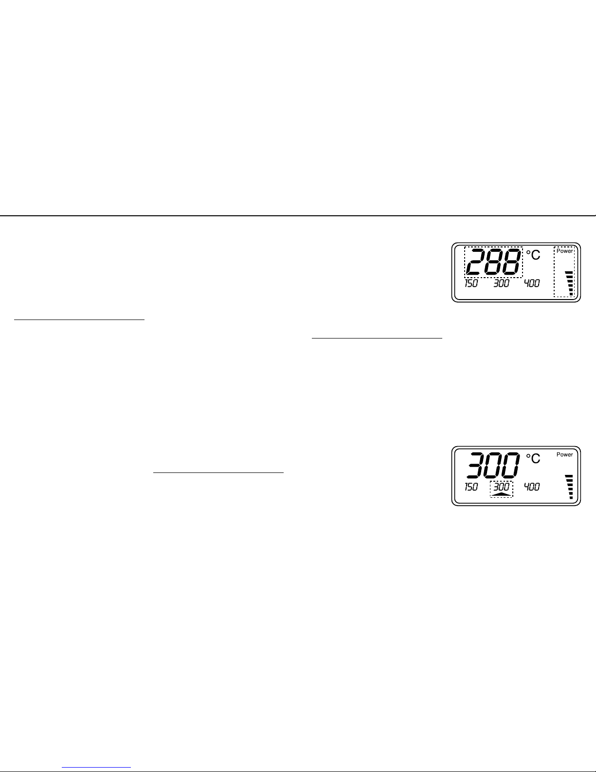
2. Switching on
Press “Power” to switch on. The processor will
perform a display test by activating all 108 segments
for approximately two seconds. The soldering
iron will then heat up to the set point temperature
when it was last used. The LCD shows the current
temperature in the main display and the “Power”
bar-chart (which can be disabled) indicates the heat
being supplied to the soldering iron; (see Figure 1).
The soldering iron tip is maintained at a constant
temperature when the set point temperature is
reached.
Figure 1
3. Adjusting the set point temperature
The main display section will change to show the set
point temperature when either the “+” or “-“ keys are
pressed. The temperature can be jogged up or down
in 1° steps or in 10° steps if the key is held. Release
key when the desired temperature is reached.
4. Selecting one of the programmed set
point temperatures
The station is pre-programmed with three set
point temperatures, 150°C, 300°C and 400°C,
and displayed directly above the corresponding
“T1”/”T2”/”T3” keys. The main display shows the
new set point temperature for approximately three
seconds when the relevant key is pressed;
(
see Figure 2
).
Figure 2
5. Modifying the programmed set point
temperatures
To change the programmed set point temperatures,
use the “+”/”-“ keys whilst holding down the
appropriate “T1”/”T2”/”T3” key. The new temperature
will be saved as soon as the keys are released.

6
Digital Soldering Station, Model № DS80
7
Digital Soldering Station, Model № DS80
6. Manual standby function
This function enables the device to cool down to “T1”
mode when the button is pressed which will then
be indicated by the “Standby” segment in the LCD
display (see Figure 3). Pressing “T1” again will
re-activate the previous set point temperature.
Figure 3
The station is shipped with the standby function
disabled. To enable the function, press “T1”, “T2”,
“T3” together to switch the DS80 into programming
mode. The “Prog” segment will be indicated on the
display (see Figure 4).
Figure 4
Now press the “T1” key. An arrow will indicate that
the standby function is enabled; (see Figure 5).
The display will revert back to normal mode after
three seconds.
Figure 5
7. Timer-controlled standby function
This enables the iron to automatically cool down
to the standby temperature after a set period of
time since the last key was pressed. The device
is shipped with the timer-controlled standby
function disabled. To enable, switch the DS80 to
programming mode as shown above and press and
hold the “T1” key. Use the “+”/”-“ keys to adjust the
timeout; (see Figure 6). Maximum time is 9 hours
and 55 minutes.
Note: The programmed timeout data will only
become valid after switching the solder station off
and then back on.
Figure 6
8. Automatic power-off function
This enables the device to automatically switch
off after a set period of time since the last key was
pressed. The device is shipped with the automatic
power-off function disabled. To enable, switch the
DS80 to programming mode as shown above and
press and hold the “T2” key. Use the “+”/”-“ keys
to adjust the power-off timeout; (see Figure 7).
Maximum time is 9 hours and 55 minutes.
Note: The programmed power-off data will only
become valid after switching the solder station off
and then back on.
Figure 7
9. Disabling the “Power” bar-chart
Switch the DS80 to programming mode as shown
above and press the “T2” key. The arrow segment
above this key will disappear; (see Figure 8).
Pressing the “T2” key again will re-enable the
bar-chart display.
Figure 8
10. Switching between °C (Celsius)
and °F (Fahrenheit)
Switch the DS80 to programming mode as shown
above and press the “T3” key. The arrow segment
above this key will disappear; (see Figure 9).
Pressing the “T3” key again will switch the display
back to °C and the arrow will reappear.
Figure 9
11. Static Bonding / EPA Point
Socket for 4mm ‘Banana’ Plug. Provided for critical
applications, where a grounding link is required to
equalise the soldering station potential to the working
area, to minimise any potential voltage difference
between the soldering tip and circuit board. For
suitable 1.8m long coiled grounding cord with 4mm
Banana plug and 10mm Stud, see RS 552-898.
(EPA = Equalised Potential Area)
Table of contents
Other RS PRO Soldering Gun manuals