RS PRO HE14 IDT Manual

Issued / Herausgegeben / Pubblicato 09/1998 V10028
(Plier/base) 186-2685
(Single row carriage) 186-2691
(Double row carriage) 186-2708
RS Stock No.
HE14 IDT Production Tool
Utensili per Terminazioni a
Perforazione di Isolante HE14
Instruction Leaflet
Bedienungsanleitung
Foglio d’instruzioni
HE14 IDT Produktionswerkzeug
A. Connector body level with carriage wall
(double row carriage only)
B. Double row carriage
C.Single row carriage
D.Plier/base
Assembly instructions
Plier/base RS stock no. 186-2685 is used in conjunction with single
row carriageRS stock no. 186-2691 to terminate IDTsockets RS stock
nos. 532-210 to 532-276 and with double row carriage RS stock no.
186-2708 to terminate IDT sockets RS stock nos. 532-282 to 532-327.
Use IDT ribbon cable or discrete wire (28 to 26 a.w.g. 0.08 to
0.12mm2).
Single row IDT socket termination
A. Cable clamp
B. Fit connector into either corner
C. Channel
D. Ball indent
1
2

2
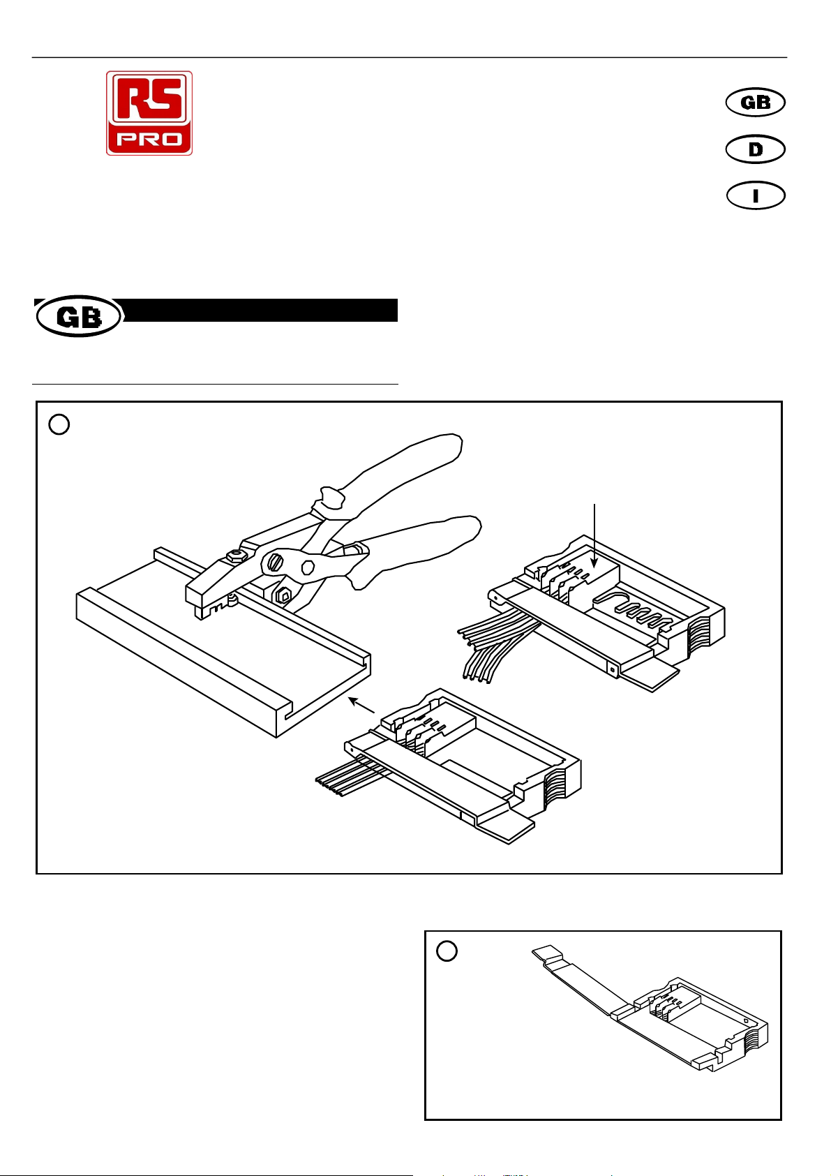
As shown in figure 2. with the cable clamp released back, fit a single
row socket into either corner of the carriage. Snap the connector into
the channel against the ball indent to secure in position.
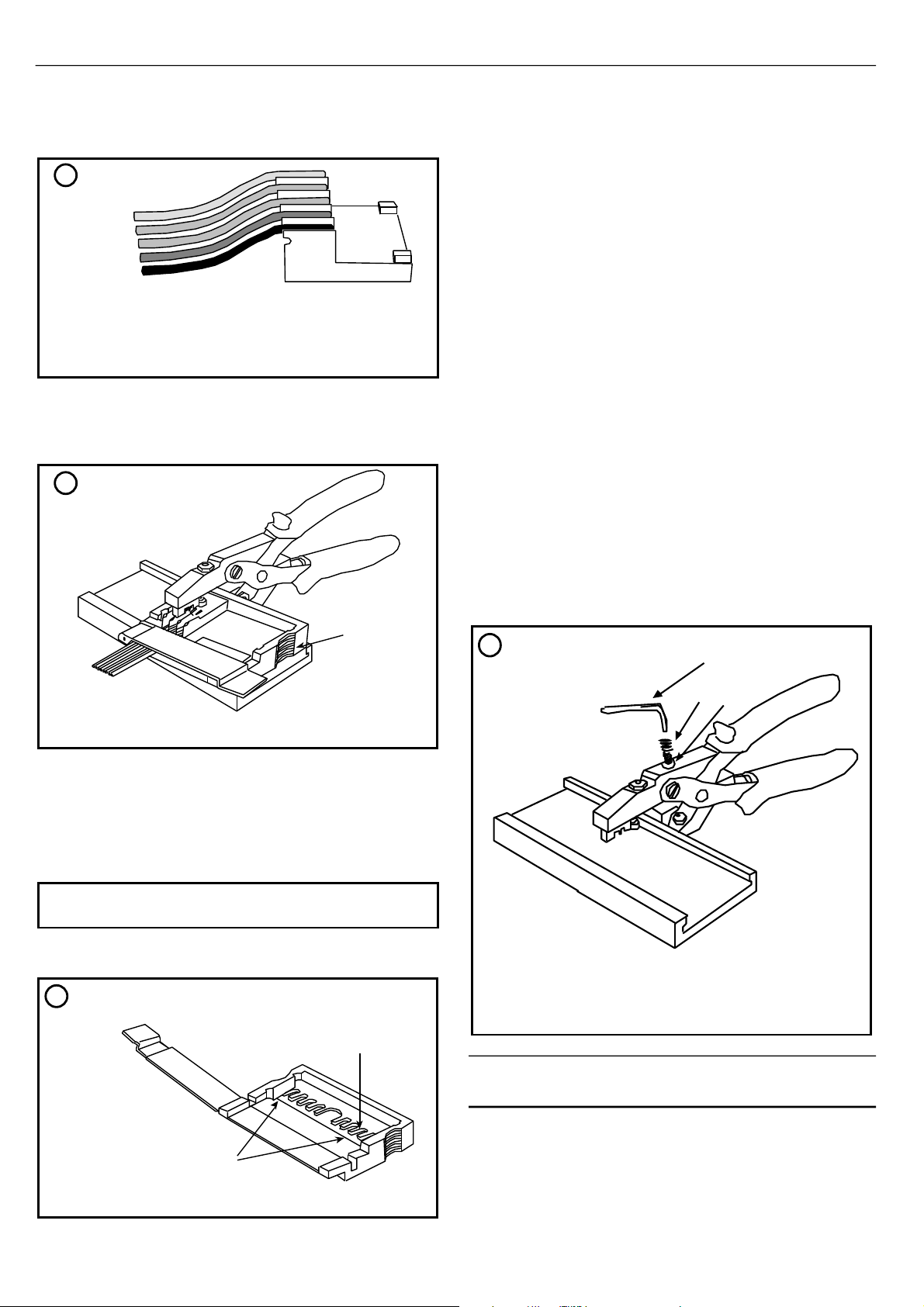
Lay the cable or discrete wires against the connector. Push wires into
the connector channels so that they are retained, see figure 3. Close
the cable clamp down so that it clips on the carriage, firmly holding the
cable. The carriage is now ready to load into the plier base.
Slide the carriage into the plier base as shown in figure 1. Provided the
connector is set in the corner of the carriage then the first terminating
position will be when the carriage is flush with the end of the base, see
figure 4.
Operate the plier to terminate the first position. The carriage should be
indexed to the next position by pushing it along the base. Continue
terminating and indexing until the connection is complete. Slide the
carriage out, and release the cable clamp to remove the assembly.
Double row IDT socket termination
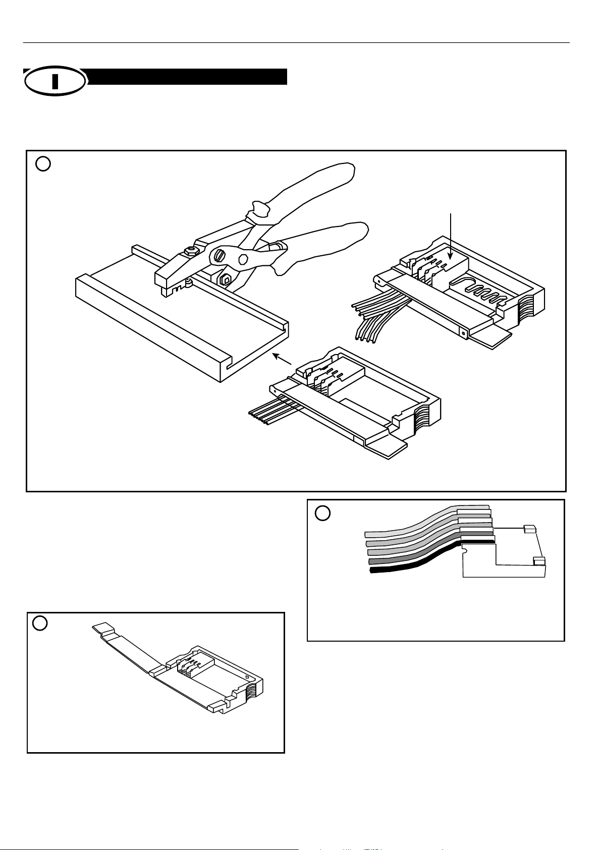
Taking the double row carriage, with the cable clamp released back,
fit a double row socket into either corner of the carriage as indicated
in figure 5. The connector should seat onto the registration slots so
that the connector body is level with the carriage wall, see figure 1.
Lay the cable into the connector channels as shown in figure 3, pushing
the wires down so they are retained. Clip the cable clamp down to hold
the cable firmly.
Slide the carriage into the plier base and locate the first position with
the carriage flush to the base end (see figure 4). Follow the terminating
procedure as for single row sockets.
When the 1st row is complete, release the connector and turn it over to
terminate the other side following the same procedure as before.
Note: For double row sockets, the first row must be terminated before
pre-loading the second row with cable.
Adjustment
An M3 cap screw and locknut are provided to adjust the insertion depth
of the wires into the IDC.
To adjust, loosen the locknut, rotate the cap screw with the Hex key
provided and re-tighten the locknut.
The tool is preset for 28 to 26 a.w.g. wires with outside diameter (over
the insulation) of 0.9mm.
If the tool is used with wires with thinner insulation (overall diameter
less than 0.9mm), increase the depth of insertion by rotating the cap
screw anticlockwise.
For wires with thicker insulation (overall diameter more than 0.9mm),
decrease the depth of insertion by rotating the cap screw clockwise.
Ensure that the locknut is tight when the tool is in use.
Never rotate the cap screw sufficiently far anticlockwise that it fails to
function as a stop. If the stop screw is ineffective, the full handle
pressure will be applied to the carriage and damage caused to the wire
and connector.
RS Components shall not be liable for any liability or loss of any nature (howsoever
caused and whether or not due to RS Components’negligence) which may result
from the use of any information provided in RS technical literature.
A
BC
The carriage can be fed into the plier base from the
left or right hand side
V10028
A. Push wires into connector channels
A. Regristration slots
B. Fit connector into either corner
A. Hex key
B. Cap screw
C. Locknut
A. Start position, carriage flush with end of base
3
4
5
6

3
(Zange/Sockel) 186-2685
(Einreihiger Schlitten) 186-2691
(Zweireihiger Schlitten) 186-2708
RS Best-Nr.
V10028
A. Steckverbindergehäuse mit Schlittenwand
(nur zweireihiger Schlitten)
B. Zweireihiger Schlitten
C. Einreihiger Schlitten
D. Zange/Sockel
Montageanweisungen
Zange/Sockel RS Best-Nr. 186-2685 wird in Verbindung mit dem
einreihigen Schlitten RS Best-Nr. 186-2691 benutzt, um die IDT-
Buchsen, RS Teilenummern 532-210 bis 532-276 abzuschließen und
dem zweireihigen Schlitten RS Best-Nr. 186-2708, um die IDT-
Buchsen, RS Teilenummern 532-282 bis 532-327 abzuschließen.
Einreihiger IDT-Buchsenabschluß
Wie in Abbildung 2 (mit der zurückgezogenen Kabelklemme) gezeigt
wird, ist eine einreihige Buchse in jede Ecke des Schlittens
einzusetzen. Buchse im Kanal im Kugeleindruck einrasten lassen,
damit diese fest sitzt.
Das Kabel oder die diskrete Verdrahtung an den Steckverbinder legen.
Verdrahtung in die Steckverbinderkanäle drücken, so daß diese dort
gehalten werden, siehe Abbildung 3. Kabelklemme nach unten
klappen, so daß diese den Schlitten verschließt und das Kabel fest an
seinem Platz hält. Der Schlitten kann nun in den Zangensockel
eingelegt werden.
A. Kabelklemme
B. Buchse in jede Ecke einsetzen
C. Kanal
D. Kugeleindruck
A. Drähte in die Steckverbindrkanäle drücken
1
2
3

4
Schlitten in den Zangensockel schieben (siehe Abbildung 1). Wenn der
Steckverbinder in der Ecke des Schlittens richtig eingesetzt ist, dann
befindet sich die erste Abschlußposition dort, wo der Schlitten mit dem
Ende des Sockels fluchtet (siehe Abbildung4).
Zange betätigen, um die erste Position abzuschließen. Der Schlitten
sollte in der nächsten Stellung einrasten. Dazu Schlitten entlang dem
Sockel schieben. Den Vorgang wiederholen, bis der Anschluß komplett
abgeschlossen ist. Schlitten herausschieben und Kabelklemme lösen,
um die fertige Buchse herauszunehmen.
Zweireihiger IDT-Buchsenabschluß
Den doppelreihigen Schlitten (die Klemme ist zurückgezogen) nehmen
und in jede Ecke des Schlittens eine doppelreihige Buchse einsetzen
(siehe Abbildung 5). Der Steckverbinder sollte so in den
Registrierschlitzen sitzen, daß das Steckverbindergehäuse auf
gleicher Höhe mit der Schlittenwand ist (siehe Abbildung 1).
Kabel in die Steckverbinderkanäle legen (siehe Abbildung 3), Drähte
nach unten drücken, so daß sie gehalten werden. Kabelklemme nach
unten klappen, um das Kabel festzuhalten.
Schlitten in Zangensockel schieben und so anordnen, daß sich die
erste Position dort befindet, wo der Schlitten mit dem Ende des
Sockels fluchtet (siehe Abbildung 4). Verbindung abschließen wie bei
den einreihigen Buchsen.
Wenn die Verbindung der ersten Reihe abgeschlossen ist,
Steckverbinder herausnehmen und umdrehen, um die Verbindung auf
der anderen Seite fortzusetzen.
Hinweis: Bei zweireihigen Buchsen muß die Verbindung der ersten
Reihe abgeschlossen sein, bevor die Verbindung der
zweiten Reihe mit dem Kabel durchgeführt werden kann.
RS Components haftet nicht für Verbindlichkeiten oder Schäden jedweder Art (ob auf
Fahrlässigkeit von RS Components zurückzuführen oder nicht), die sich aus der
Nutzung irgendwelcher der in den technischen Veröffentlichungen von RS
enthaltenen Informationen ergeben.
Der Schlitten kann von links nach rechts in den Zangensockel
geschoben werden
V10028
A. Anfangsstellung. Der Schlitten fluchter mit dem Ende
des Sockels.
A. Registrierschlitze
B. Buchse in jede Ecke einsetzen
4
5

5
(Pinza/Base) 186-2685
(Carrello a fila singola) 186-2691
(Carrello a fila doppia) 186-2708
RS Codici.
V10028
A. Corpo del connettore in piano con la parete del carrello
(solo carrello a doppia fila)
B. Carrello a doppia fila
C. Carrello a fila singola
D. Pinza/Base
Instruzioni per il montaggio
La pinza/base (codice RS 186-2685) viene usata insieme al carrello a
fila singola (codice RS 186-2691) per terminare le prese IDT
(terminazioni a perforazione di isolante) da RS 532-210 a 532-276, e
con il carrello a doppia fila RS 186-2708 per la terminazione di prese
IDT da RS 532-282 a 532-327. Usare il cavo piatto IDT a filo discreto
(da 28 a 26 a.w.g. da 0,08 a 0,12mm2)
Terminazione di prese IDT a fila singola
Come mostrato in figura 2, con il fermacavo aperto, inserire una presa
a fila singola in uno degli angoli del carello. Agganciare il connettore
nel canale a ridosso della tacca sferica per fissarlo in posizione.
Disporre il cavo o i fili discreti contro il connettore. Spingere i fili nei
canali del connettore in modo che rimangano bloccati (vedi figura
3).Chiudere il fermacavo in modo che si agganci sul carrello e
trattenga saldamente il cavo. Il carrello è ora pronto per essere
caricato nella base della pinza.
A. Fermacavo
B. Inserire il connettore in uno dei due angoli
C. Canale
D. Tacca sferica
A. Spingere i fili nei canali del connettore
1
2
3

6
Inserire il carrello nella base della pinza, come mostrato in figura 1. A
condizione che il connettore sia fissato nell’angolo del carrello, si
ottiene la prima posizione di terminazione quando il carrello è a filo con
l’estremità della base (vedi figura 4).
Azionare la pinza per terminare la prima posizione. Spingere il carrello
lungo la base per farlo avanzare alla posizione successiva. Proseguire
la terminazione e gli avanzamenti fino al completamento della
connessione. Sfilare il carrello e sbloccare il fermacavo per rimuovere
il complessivo.
Terminazione di prese IDT a doppia fila
Usando il carrello a doppia fila, con il fermacavo aperto, installare una
presa a doppia fila in uno degli angoli del carrello, come indicato nella
figura 5. Il connettore va alloggiato nelle fessure di registrazione, in modo
che il suo corpo sia in piano con la parete del carrello (vedi figura 1).
Disporre il cavo nei canali del connettore, come mostrato in figura 3, e
spingere i fili verso il basso in modo che rimangano bloccati. Chiudere
il fermacavo per bloccare saldamente il cavo.
Inserire il carrello nella base della pinza e localizzare la prima
posizione, con il carrello in piano con l’estremità della base (vedi figura
4). Seguire la procedura di terminazione relativa alle prese a fila
singola.
Una volta completata la prima fila, sbloccare il connettore e rovesciarlo
per terminare l’altro lato, seguendo la stessa procedura di prima.
Nota: nelle prese a doppia fila bisogna terminare la prima fila prima
di precaricare la seconda con il cavo.
La RS Components non si assume alcuna responsabilità in merito a perdite di
qualsiasi natura (di qualunque causa e indipendentemente dal fatto che siano dovute
alla negligenza della RS Components), che possono risultare dall’uso delle
informazioni fornite nella documentazione tecnica.
Il carrello può essere inserito nella base della pinza dal lato
sinistro o dal lato destro
V10028
A. Posizione di partenza. Carrello in piano con l’estremità della base
A. Fessure di registrazione
B. Inserire il connettore in uno dei due angoli
4
5
Table of contents
Languages:
Other RS PRO Tools manuals