RSF Elektronik AK MS 15 User manual

MONTAGEANLEITUNG
MOUNTING INSTRUCTIONS
AK MS 15
Abtastkopf
Scanning head
Ausgabe 06/2020 Art.Nr. 1250630-01 Dok.Nr. D1250630-05-A-02

AK MS 15
02
Seite / Page
1Einleitung ............................................................................................ 03
Introduction ........................................................................................... 03
2Technische Daten .......................................................................... 04 − 05
Technical data ................................................................................. 04 − 05
3Sicherheitshinweise .............................................................................. 06
Safety notes .......................................................................................... 06
4Montagevorbereitungen ........................................................................ 07
Mounting preparations ............................................................................ 07
5Montage ....................................................................................... 08 − 09
Mounting ........................................................................................ 08 − 09
6Montagemöglichkeiten .......................................................................... 10
Mounting possibilities ............................................................................ 10
7Abschließende Arbeiten ......................................................................... 11
Final steps ............................................................................................ 11
8Testlauf, Betrieb .................................................................................... 12
Test running, operation ............................................................................. 12
9Wartung, Reparatur ............................................................................... 13
Maintenance, repair ................................................................................ 13
10 Demontage, Umweltschutz, Entsorgung ........................................... 14 − 15
Demounting,environmental protection, disposal ................................... 14 − 15
INHALT / CONTENT
Inhalt / Content

AK MS 15 03
Einleitung / Introduction 1
Lesen Sie die Montageanleitung sorgfältig und bewahren Sie sie gut auf.
Verfügbar unter: https://www.rsf.at/de/service-support/downloadbereich
Carefully read the mounting instructions and keep them safely.
Available at: https://www.rsf.at/en/service-support/downloads
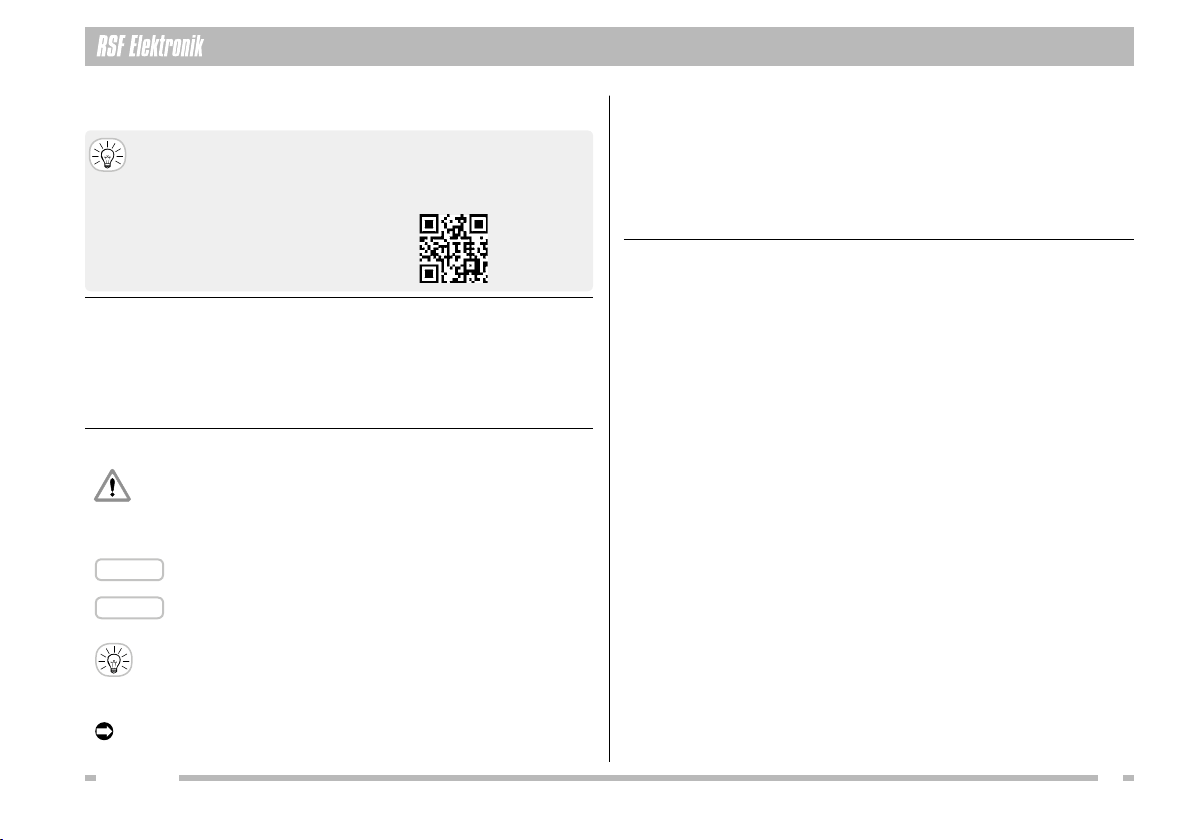
Sehen Sie sich auch die 3D-Montagevideos
zu diesen Messgeräten an:
Also watch the 3D mounting videos
for these encoders:
Dieses Symbol kennzeichnet wichtige Hinweise,
die Personenschäden verhindern.
This symbol indicates important information that prevents
personal injuries.
Dieses Signalwort kennzeichnet wichtige Hinweise,
die Sachschäden verhindern.
This signal word indicates important information that prevents
damage to property.
Dieses Symbol kennzeichnet nützliche Tipps, Empfehlungen
sowie zusätzliche Informationen.
This symbol indicates useful tips, recommendations and addi-
tional information.
Dieses Symbol kennzeichnet Handlungsanweisungen.
This symbol indicates instructions.
1.1 VORWORT / PREAMBLE
1.3 SYMBOLE / SYMBOLS
HINWEIS
NOTICE
Die MS 15 Längenmessgeräte entsprechen den Vorgaben folgender EU-Richtlinien:
EMV-Richtlinie 2014/30/EU RoHS-Richtlinie 2011/65/EU, 2015/863/EU
The MS 15 linear encoders comply with the specications of the following EU directives:
EMV-directive 2014/30/EU RoHS-directive 2011/65/EU, 2015/863/EU
1.2 KONFORMITÄT MIT RICHTLINIEN / DIRECTIVES CONFORMITY
Die MS 15 Längenmessgeräte dürfen nur zur Ermittlung von Längen- bzw. Wegin-
formationen verwendet werden. Jeder andere Gebrauch kann Personen- bzw. Sach-
schäden verursachen!
The MS 15 linear encoders may only be used to determine length and path information.
Any other use may cause personal injury or property damage!
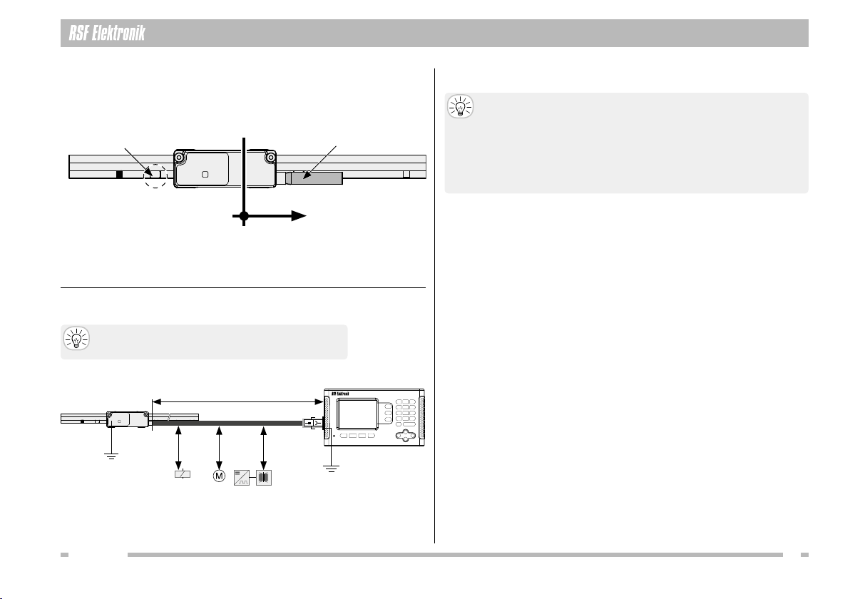
SPANNUNGSVERSORGUNG
Schließen Sie RSF Elektronik Messgeräte nur an Folge-Elektroniken an, deren Ver-
sorgungsspannung aus PELV-Systemen (EN 50 178) erzeugt wird.
RSF Elektronik Messgeräte erfüllen die Anforderungen der Norm IEC 61010-1 nur,
wenn die Spannungsversorgung aus einem Sekundärkreis mit begrenzter Energie
nach IEC 61010-13rd Ed., Abschnitt 9.4 oder mit begrenzter Leistung nach IEC 60950-1
2nd Ed., Abschnitt 2.5 oder aus einem Sekundärkreis der Klasse 2 nach UL1310 erfolgt.1)
1) Anstelle der IEC 61010-13rdEd., Abschnitt 9.4 können auch die entsprechenden Abschnitte
der Normen DIN EN 61010-1, EN61010-1, UL 61010-1 und CAN/CSA-C22.2 No. 61010-1 bzw.
anstelle der IEC 60950-12nd Ed., Abschnitt 2.5 die entsprechenden Abschnitte der Normen
DIN EN60950-1, EN60950-1, UL60950-1, CAN/CSA-C22.2 No. 60950-1 verwendet werden.
VOLTAGE SUPPLY
Connect RSF Elektronik encoders only to subsequent electronics whose power supply is
generated from PELV systems (EN 50 178).
RSF Elektronik encoders fulll the requirements of standard IEC 61010-1 only if the po-
wer is supplied from a secondary circuit with current limitation as per IEC 610103rd Ed.,
Section 9.4 or with power limitation as per IEC 60950-12nd Ed., Section 2.5 or from a
Class 2 secondary circuit as specified in UL1310.1)
1) In place of IEC 61010-1
3rdEd., Section 9.4, the corresponding sections of standards DIN EN
61010-1, EN61010-1, UL 61010-1 and CAN/CSA-C22.2 No. 61010-1 can be applied and in place of
IEC 60950-12nd Ed., Section 2.5 the corresponding sections of standards DIN EN60950-1,
EN60950-1, UL60950-1, CAN/CSA-C22.2 No. 60950-1 can be applied.
1.4 BESTIMMUNGSGEMÄßER GEBRAUCH / INTENDED USE
1.5 ALLGEMEINE ELEKTRISCHE HINWEISE
GENERAL ELECTRICAL INFORMATION

AK MS 15
04
2 Technische Daten / Technical data
2.1 SPEZIFIKATION / SPECIFICATION
2.1.2 ALLGEMEINE DATEN / GENERAL DATA
Zulässige Vibration:
Permissible vibration:
150 m/s2(55 bis / to 2000 Hz)
Zulässiger Schock:
Permissible shock:
750 m/s2 (8 ms)
Zulässige Temperatur:
Permissible temperature:
–20 °C bis / to +70 °C
bei Lagerung / storage
0 °C bis / to +50 °C
im Betrieb / operation
Spannungsversorgung:
Power supply:
TTL:
+5 V ±10 %,
max. 160 mA
(ohne Last / unloaded)
1 Vss / 1 Vpp:
+5 V ±10 %,
max. 160 mA
(ohne Last / unloaded)
Schutzart (EN 60529): IP40
Protection (EN 60529): IP40
2.1.1 ABTASTKOPF / SCANNING HEAD
Gerätetyp
Model
Ausgangssignale
Output signals
Messschritt [µm]
System resolution [µm]
Integrierte Interpolation
Integrated interpolation
MS 15 1 Vss Je nach ext. Unterteilung
Dep. on external interpolation--
MS 15 TTLx1u 10,00 1fach / times 1
MS 15 TTLx5 2,00 5fach / times 5
MS 15 TTLx10 1,00 10fach / times 10
MS 15 TTLx20 0,50 20fach / times 20
MS 15 TTLx25 0,40 25fach / times 25
MS 15 TTLx50 0,20 50fach / times 50
MS 15 TTLx100 0,10 100fach / times 100
MS 15 TTLx200 0,05 200fach / times 200
2.1.3 TYPENSCHILD / LABEL
1:
P:
AK MS15: Produktname / Product name
ID: Teilenummer / Part number
SN: Seriennummer mit Änderungsindex, z. B. „A“
Serial number with change index, e. g. “A“
T8: Herstellungsdatum / Manufacturing date
Endlagenschalter S1 / S2 (Schaltsignale)
Limit switches S1 / S2 (switch signals)
H: TTL (active high)
Z: Open collector (active high impedance)
L: TTL (active low)
C: Open collector (active low)
K: Ohne Funktion / Without function
Geeignet für Teilungsart
Suitable for graduation type
P: Stahlmaßband geschwärzt auch für MP-Träger
Steel tape blackened also for MP carrier
G: Chromteilung auf Glas / Chrome graduation on glass
Referenzmarke / Reference mark
1: Wählbar / Selectable
2: Wählbar mit Schaltsignal S2 / Selectable with switch signal S2
A: Aktiv / Active
K: Deaktiviert / Deactivated
H H:
S2S1
TTLx100: Ausgangssignal / Output signal
TTL 100-fach / TTL times 100
Messschritt / System resolution:
Messschritt = Teilungsperiode / Grating period
S. resolution = 4 × Interpolation / Interpolation
Messschritt = 40 µm = 0,1 µm
S. resolution = 4 × 100
0.100µs: Flankenabstand (TTL) amin (2% Tol.)
Edge separation (TTL) amin (2% tol.)
Max. Verfahrgeschwindigkeit / Max. velocity:
vmax = Teilungsperiode / Grating period
4 × amin × Interpolation / Interpolation
vmax = 40 µm = 1,0 m/s
4 × 0,1 µs × 100

AK MS 15 05
2.2 ABMESSUNGEN / DIMENSIONS
Technische Daten / Technical data 2

AK MS 15
06
3 Sicherheitshinweise / Safety notes
Die Montage der Längenmessgeräte erfordert gute mechanische und elektronische
Kenntnisse und eine präzise und sichere Arbeitsweise! Führen Sie die Montage nur
durch eine ausgebildete Fachkraft unter Einhaltung der örtlichen Sicherheitsbe-
stimmungen durch!
The mounting of the linear encoders requires great mechanical and electronical
knowledge, moreover precise and safe operation! Therefore, mounting should only
be carried out by a qualied specialist in compliance with local safety regulations!
3.1 PERSONENSCHUTZ / PERSONAL SAFETY 3.2 GERÄTESCHUTZ / DEVICE SAFETY
Schalten Sie alle von der Montage bzw. Reparatur betroffenen Geräte /
Maschinen / Anlagen vollständig ab! Trennen Sie die Geräte /
Maschinen / Anlagen gegebenenfalls vom Stromnetz und machen Sie
die Pneumatik drucklos!
Before mounting, switch off all the devices / machines / plants affected.
If appropriate, isolate the devices / machines / plants from the mains and
remove the pressure from pneumatic.
BenützenSiegeeigneteSchutzausrüstungfür dieMontage /Demontage
(Handschuhe, Schutzbrille).
Wear suitable protective equipment for mounting / demounting
(gloves, goggles).
HINWEIS
NOTICE
Beachten Sie die Handhabungsvorschriften für elektrostatisch
gefährdete Bauelemente!
Observe precautions for handling of electrostatic sensitive devices!
Reinigungsmittel Gehäuse und Abtastplatte
Cleaning agents housing and scanning reticle
Erlaubt / Allowed Verboten / Prohibited
Weiches, fusselfreies,
nicht scheuerndes Putztuch
Soft, lintfree, not rubbing cloth
Scheuer- und Poliermittel
Abrasives, polishes
Wasser / Water
Hochprozentige, alkoholische Reiniger
oder Lösungsmittel, z. B. Aceton,
(Iso)Propanol, Ethanol
High-proof alcoholic cleaners or solvents,
e. g. acetone, (iso)propanol, ethanol
Agressive oder korrosive Mittel,
z. B. starke Säuren, Ammoniak
Agressive or corrosive media,
e. g. strong acids, ammonia
Aceton bei Reflexionslichtschranken
Acetone at reflexion light barriers
Reinigungsmittel Kabel / Cleaning agents cable
Erlaubt / Allowed Verboten / Prohibited
Alkoholfreie Reiniger / Non-alcoholic cleaner Aceton / Acetone Ethanol
Verlegen Sie das Kabel vom Abtastkopf zur Steuerung so, dass es
im Betrieb beim Abfahren der Messstrecke nicht hängen bleibt;
nicht gequetscht, abgeknickt oder anderweitig beschädigt wird;
nicht direkt neben Energieleitungen verläuft.
Lay the cable from the scanning head to the control in such a way that
it does not get caught up in operation when moving along the machine travel;
it is not crushed, kinked or otherwise damaged;
it does not run directly alongside power lines.

AK MS 15 07
Montagevorbereitungen / Mounting preparations 4
4.1 ZÄHLRICHTUNG / COUNTING DIRECTION
4.3 STÖRQUELLEN / SOURCES OF INTERFERENCE
4.2 MONTAGEFLÄCHE / MOUNTING SURFACE
> 200 mm
≤ 30 000 mm
Störquellen
Noise sources
> 100 mm> 100 mm
Halten Sie den Mindestabstand von Störquellen ein.
Keep minimum distance from sources of interference.
Reinigen Sie die Montagefläche vor der Montage.
Sie muss sauber, fett- und lackfrei sein.
Clean the mounting surface before mounting.
It has to be clean and free of grease or varnish.
Anforderungen an die Montageflächen siehe Abmessungen (s. S. 05).
Demands for mounting see in dimensions (see page 05).
+
Kabel / Cable
Referenzmarke
Reference mark
Bewegungsrichtung des Abtastkopfes für positive Zählrichtung
Direction of motion of the scanning head for positive counting direction

AK MS 15
08
HINWEIS
NOTICE
D
MONTAGEANLEITUNG
MOUNTINGINSTRUCTIONS
AK MS 15
Abtastkopf
Scanninghead
Ausgabe 07/2018 Art.Nr. 1250630-01 Dok.Nr. D1250630-00-B-01
Entfernen Sie die Schutzhaube vorsichtig.
Remove the protection cover carefully.
Reinigen Sie die Abtastplatte bei Bedarf.
Clean the scanning reticle if necessary.
5 Montage / Mounting
5.1 GERÄT AUSPACKEN / UNPACK ENCODER 5.2 SCHUTZHAUBE ENTFERNEN / REMOVE PROTECTION COVER
Schutzhaube / Protection cover
Beschädigungsgefahr durch spitzes Werkzeug!
Die Abtastplatte ist hochsensibel und kann durch Kratzer beschädigt
werden.
Entfernen Sie die Schutzhaube nur mit einem stumpfen Werkzeug.
Risk of damage due to sharp tool!
The scanning reticle is highly sensitive and can be damaged by scratches.
Remove the protection cover only with a blunt tool.
B
C
E
A
Abtastplatte / Scanning reticle
Finden Sie Ihre Steckerbelegung unter:
http://www.rsf.at/de/service-support/downloadbereich/
Find your pin assignment on:
http://www.rsf.at/en/service-support/downloads/
Verwenden Sie die Teilenummer (ID) vom Typenschild (s. S. 04)
ODER die Dokumentennummer von Ihrem Lieferschein für die Online-
suche. Tragen Sie die Nummer im Suchfeld ein.
Take the part number (ID) from your label (see page 04) OR
the document number from your delivery note for the online search.
Enter the number into the search box.
Anschluss-Belegung: D1143258
Pin conguration: D1143258
AMS 15 Abtastkopf AK
MS 15 scanning head AK
BMontageanleitung
Mounting instructions
CAbstandsfolie 0,55 mm
Gap foil 0.55 mm
DLieferschein / Delivery note
EHersteller-Prüfzertikat
Manufacturer’s inspection certicate

AK MS 15 09
HINWEIS HINWEIS
NOTICE
NOTICE
Montage / Mounting 5
5.3 ABSTAND / GAP 5.4 ABTASTKOPF ANSCHRAUBEN / MOUNTING SCANNING HEAD
Legen Sie die Abstandsfolie zwischen Maßverkörperung und Abtastkopf gemäß
der Grak unten ein. Verwenden Sie die mitgelieferte Abstandsfolie.
Insert the gap foil between graduation carrier and scanning head according to
the drawing below. Only use the included gap foil.
Drücken Sie den Abtastkopf beim Anschrauben leicht in Richtung Abstandsfolie.
Push the scanning head sligthly in the direction of the gap foil while screwing on.
Ziehen Sie die Montageschrauben abwechselnd mit max. 1,2 Nm an.
Beachten Sie die Angaben bezüglich Toleranzen und Freiheitsgraden (s. S. 10).
Screw on the mounting screws alternately with max. 1.2 Nm.
Observe the detailes for tolerances and variances (see page 10).
Entfernen Sie die Abstandsfolie nach Festziehen der Montageschrauben.
Remove the gap foil after tightening the mounting screws.
Beschädigung des Geräts durch falschen Abstand!
Der Arbeitsabstand zwischen Abtastkopf und Maßverkörperung muss
0,55 ±0,2 mm sein. Durch einen zu kleinen Abstand zerkratzt die Abtast-
platte oder die Maßverkörperung oder beides.
Verwenden Sie die mitgelieferte Abstandsfolie oder Teile der Schutzhaube.
Risk of damage due to a wrong gap!
The working gap between scanning head and graduation carrier has to be
0.55 ±0.2mm.Due to a minor gap the scanning reticle or the graduation
carrier scratches or both.
Use the included gap foil or protection cover parts.
Beschädigung durch falsches Drehmoment!
Zu festes Anschrauben beschädigt den Abtastkopf.
Beachten Sie das Drehmoment und die Mindest-Einschraublänge
der Montageschrauben (s. S. 10).
Risk of damage due to a wrong tightening torque!
Over-tightening will damage the scanning head.
Observe the tightening torque and the minimum screwing length (see page 10).
Max. 1,2 Nm

AK MS 15
10
6 Montagemöglichkeiten / Mounting possibilities
6.1 MONTAGEMÖGLICHKEITEN AK MS 15 / MOUNTING POSSIBILITIES AK MS 15
6.2 MONTAGE AK ZU MAßVERKÖRPERUNG / MOUNTING AK TO GRADUATION CARRIER
6.2.1 MS 15 MK 6.2.2 MS 15 MD 6.2.3 MS 15 MP 6.2.4 MS 15 BK, GK
Detail MP
= Kundenseitige Anschlussmaße / Required mating dimensions ΔY, Z = s. S. 05 / see page 05

AK MS 15 11
Abschließende Arbeiten / Final steps 7
7.1 KABEL VERLEGEN / LAY CABLE
7.3 SCHUTZ ANBRINGEN / MOUNT PROTECTION
7.2 ELEKTRISCHER TEST / ELECTRICAL TEST
7.2.2 SCHIRMUNG / SHIELDING
7.2.1 WIDERSTAND PRÜFEN / CHECK RESISTANCE
Prüfen Sie den elektrischen Widerstand zwischen Steckergehäuse und Maschine.
Sollwert: max. 1 Ω
Check the resistance between the connector housing and the machine.
Nominal value: max. 1 Ω
Verbinden Sie den Schirm mit der Maschinenerde (Feldmasse).
Connect the shield with the machine ground (eld mass).
HINWEIS
NOTICE
Elektrischer Kurzschluss!
Das Längenmessgerät ist nicht gegen das Eindringen von starken
Verschmutzungen oder Wasser geschützt.
Schützen Sie das Längenmessgerät durch Anbringen eines Schutz-
blechs oder Ähnliches.
Electrical short circuit!
The linear encoder is not protected against intrusion of intense contami-
nation or water.
Protect the linear encoder by applying a protective cover or similar.
Verlegen Sie das Kabel so, dass die minimalen Biegeradien nicht
unterschritten werden.
Position the cable such that the cable bend radius meets or exceeds
the minimum bending radius.
Geschirmtes PUR-Kabel
Shielded PUR-cable
Für Schleppketten geeignet
Drag chain qualied
Biegeradius einmalig
Bending rad. xed mounting
Biegeradius dauernd
Bending rad. continuous flexing
HINWEIS
NOTICE

AK MS 15
12
8 Testlauf, Betrieb / Test running, operation
8.1 ÜBERPRÜFUNG DER FUNKTIONEN / INSPECTION OF FUNCTIONS
LED ANZEIGE / STATUS OF LED INFORMATION HINWEIS / NOTE
Ohne externes Prüfgerät / Without external test box
Funktionskontrolle Hauptspur / Function-control main track
LED leuchtet GRÜN / LED displays GREEN Abtastsignale sehr gut
Counting signals very good
Nach erfolgreicher Montage
After successful mounting
LED blinkt GRÜN / LED blinks GREEN Abtastsignale gut
Counting signals good
Bei Montage nicht erlaubt im Betrieb erlaubt
At mounting not allowed allowed during operation
LED blinkt ROT / LED blinks RED Abtastsignale außerhalb der Toleranz Fehler
Counting signals out of tolerance error
Anbau prüfen, Maßverkörperung reinigen
Check mounting, clean graduation carrier
Funktionskontrolle Referenzimpuls RI
Function-control reference impulse RI
Nur bei Überfahren der Referenzmarke
Only by passing the reference mark
LED blinkt ROT / LED blinks RED RI außerhalb der Toleranz
RI out of tolerance
Anbau prüfen, Maßverkörperung reinigen
Check mounting, clean graduation carrier
LED blinkt BLAU / LED blinks BLUE RI in Toleranz / RI within tolerance
Mit externem Prüfgerät / With external test box
Funktionskontrolle Hauptspur / Function-control main track
LED leuchtet GRÜN / LED displays GREEN Abtastkopf mit Spannung versorgt
Scanning head supplied with power
Auswertung der Abtastsignale über LED abgeschaltet
Evaluation of counting signals via LED not active
Funktionskontrolle Referenzimpuls RI
Function-control reference impulse RI
Nur bei Überfahren der Referenzmarke
Only by passing the reference mark
LED blinkt ROT / LED blinks RED RI ist außerhalb der Toleranz
RI out of tolerance
Anbau prüfen, Maßverkörperung reinigen
Check mounting, clean graduation carrier
LED blinkt BLAU / LED blinks BLUE RI ist in Toleranz / RI within tolerance
8.2 ZUBEHÖR / ACCESSORIES
8.2.1 EXTERNES PRÜFGERÄT
EXTERNAL TEST BOX
8.2.1 BELEGUNGSADAPTER
PINOUT ADAPTER
PWT 101: ID 1225922-01
PA2: ID 1114203-01
Belegungsadapter
RSF Elektronik Standard-
Steckerbelegung zu PWT 101
Pinout adapter RSF Elektronik
standard connector pin assignment
to PWT 101

AK MS 15 13
Wartung, Reparatur / Maintainance, repair 9
9.1 WARTUNG / MAINTENANCE
HINWEIS
NOTICE
Beschädigung durch Eigenmodikation!
Die Längenmessgeräte sind nicht für eine Eigenmodikation oder
Komponententausch durch den Kunden konzipiert.
Öffnen oder verändern Sie das Gerät niemals selbst, dadurch ent-
stehen Beschädigungen des Geräts und die Gewährleistung verfällt.
Damage due to self-modication!
The linear encoders are not designed for self-modication or component
replacement by the customer.
Never open or modify the device yourself, as this will damage the device
and void the warranty.
Nehmen Sie im Fall einer Funktionsstörung oder Beschädigung des Längen-
messgeräts Kontakt mit unserer Serviceabteilung auf.
Contact our service department in case of a malfunction or damage to the linear
encoder.
Messgeräte von RSF Elektronik sind für eine lange Lebensdauer konzipiert.
Eine vorbeugende Wartung ist nicht erfoderlich.
Sie enthalten jedoch Komponenten, die, je nach Anwendung und Handhabung,
einem Verschleiß unterliegen.
Anschlusskabel in Wechselbiegung (s. S. 11, Biegeradius dauernd).
Verschmutzte Abtastplatte.
Beachten Sie die Funktionskontrolle und die Hinweise in der Tabelle (s. S. 12).
Linear encoders from RSF Elektronik are designed for a long service life.
Preventive maintenance is not required.
However, they contain components that are subject to wear, depending on the applica-
tion and handling.
Connecting cable in alternating bending(see page 11, bending radius continuous flexing).
Contaminated scanning reticle.
Observe the function control and the notes from the table (see page 12).
9.2 REPARATUR / REPAIR
Tarsdorf 93, 5121 Tarsdorf, Österreich
Serviceabteilung / Service Department RSF Elektronik Ges.m.b.H.
+43 (0)6278 / 8192-0
FAX
+43 (0)6278 / 8192-56
E-mail: [email protected]
Internet: www.rsf.at

AK MS 15
14
10 Demontage, Umweltschutz, Entsorgung / Demounting, environmental protection, disposal
10.1 DEMONTAGE / DEMOUNTING
Die Demontage des Geräts darf nur durch Fachpersonal vorgenommen werden. Demounting of the product is only to be performed by qualied personnel.
VORSICHT Gefahr durch Splitter und scharfe Kanten!
Bei Nichtbeachtung können Verletzungen entstehen!
Benützen Sie geeignete Schutzausrüstung für die Demontage
(Handschuhe, Schutzbrille).
Biegen / verformen Sie Maßstäbe bzw. Maßbänder nicht zu stark.
Beachten Sie Sicherheitsdatenblätter von Lösungsmitteln.
CAUTION Danger from splinters and sharp edges!
Non-observance could cause injuries!
Wear suitable protective equipment for removal
(gloves, goggles).
Do not bend or deform scales or scale tapes excessively.
Comply with the safety data sheets of solvents.

AK MS 15 15
Demontage, Umweltschutz, Entsorgung / Demounting, environmental protection, disposal 10
10.2 UMWELTSCHUTZ UND ENTSORGUNG / ENVIRONMENTAL PROTECTION AND DISPOSAL
Umweltschäden durch falsche Entsorgung des Geräts, Zubehörs
oder Peripheriegeräten!
Entsorgen Sie nicht im Hausmüll.
Entsorgen Sie Elektroschrott und Elektronikkomponenten nur
durch autorisierte Annahmestellen. Sie unterliegen der Sonder-
müllbehandlung.
Beachten Sie die Vorschriften des jeweiligen Landes.
Genaue Informationen zu gesetzlichen Regelungen gibt
die zuständige Verwaltungsbehörde.
Environmental damage due to incorrect disposal of the product,
accessories or peripherals!
Do not dispose in domestic waste.
Dispose only by authorized collection points. Electrical waste and
electronic components are subject to special-waste regulations.
Observe the applicable country-specific regulations.
More detailed information on legal regulations can be obtained
from competent authorities.
NOTICEHINWEIS

Ges.m.b.H.
Elektronische Längen- und Winkelmessgeräte,
Präzisionsteilungen
Tarsdorf 93, 5121 Tarsdorf, Österreich
+43 (0)6278 / 8192-0
FAX
+43 (0)6278 / 8192-58
e-mail: [email protected]
internet: www.rsf.at
Ausgabe/Date 06/2020 Art.Nr. 1250630-01 Dok.Nr. D1250630-05-A-02
Certied acc. to
ISO 9001
ISO 14001
This manual suits for next models
9
Table of contents
Other RSF Elektronik Media Converter manuals

RSF Elektronik
RSF Elektronik MSA 771 User manual

RSF Elektronik
RSF Elektronik MSA 871 User manual

RSF Elektronik
RSF Elektronik MSA 720 User manual

RSF Elektronik
RSF Elektronik AK MSS 25 1 Vss User manual

RSF Elektronik
RSF Elektronik MS 25 MA User manual

RSF Elektronik
RSF Elektronik MS 45 MO User manual

RSF Elektronik
RSF Elektronik MS 25 User guide

RSF Elektronik
RSF Elektronik MSA 820 User manual