manuals.online logo
Brands
  1. Home
  2. •
  3. Brands
  4. •
  5. RSF Elektronik
  6. •
  7. Media Converter
  8. •
  9. RSF Elektronik MSA 720 User manual

RSF Elektronik MSA 720 User manual

MONTAGEANLEITUNG
MOUNTING INSTRUCTIONS
MSA 720
Gekapseltes Längenmessgerät
Sealed linear encoder
Ausgabe 09/2019  Art.Nr. 727461-02  Dok.Nr. D806689-03-A-01
RSF Elektronik Ges.m.b.H. A-5121 Tarsdorf  +43 (0)6278 / 8192-0 
FAX
+43 (0)6278 / 8192-79  e-mail: [email protected]  Internet: www.rsf.at 02
1 2 3
Anbaumaße / Dimensions Positive Zählrichtung
Positive counting direction
!
+
105
ML
0


45b
!
6 8
2,5 Nm
2,5 Nm
Montage möglichst nahe an der
Bearbeitungsebene! Schrauben
abwechselnd gleichmäßig anziehen!
Mount as close as possible to the working
plane! Tighten the screws equally!
7
Transportschutz entfernen!
Remove mounting bracket!
5a
1 ±0,5
RSF Elektronik Ges.m.b.H. A-5121 Tarsdorf  +43 (0)6278 / 8192-0 
FAX
+43 (0)6278 / 8192-79  e-mail: [email protected]  Internet: www.rsf.at
>200 mm
Störquellen
Noise sources
>100 mm
>100 mm
03
9
12
10
13
11
14 Eine ausreichende Entkopplung gegenüber störsignal-
führenden Kabeln wird im Allgemeinen durch einen
Luftabstand von 100 mm oder bei Verlegung in metal-
lischen Kabelschächten durch eine geerdete Zwi-
schenwand erreicht.
Gegenüber Speicherdrosseln in Schaltnetzteilen ist
ein Mindestabstand von 200 mm erforderlich.
Sufcient decoupling from interference-signal-conducting cables
can usually be achieved by an air clearance of 100 mm or, when
cables are in metal ducts, by a grounded partition.
A minimum spacing of 200 mm to inductors in switch-mode power
supplies is required.
Typ. 12 mmTyp. 12 mm
S1
S2
0=Anfang ML / Beginning ML Ende ML / End ML
S1*
30+
50+
S2*
PH 00 *= Schaltmagnet / Actuator magnet
Schaltsignale / Switch signals:
Auslieferzustand / Factory default setting:
50 50 5050
ML/2+40
ML/2
0 =Anfang ML / Beginning ML
RI*
PH 00
*= Schaltmagnet
Actuator magnet
Referenzmarke (RI) wählbar:
Reference mark (RI) selectable:
Auslieferzustand / Factory default setting:
Schema der abstandskodierten Referenzmarken (K):
Principle of the distance coded reference marks (K):
10+13T 10–13T 10+14T 10–14T
20 20
20+1T 20+1T20+1T
T = Teilungsperiode / grating period
Bei Austausch des Messgeräts muss die Steuerung neu
initialisiert werden! In case of replacement of the linear encoder,
the control has to be initialized again!
!
Abschließende Arbeiten / Final steps
Elektrischen Widerstand
zwischen Steckergehäuse
und Maschine prüfen.
Sollwert: max. 1 Ω
Check the resistance
between the connector housing
and the machine.
Nominal value: max. 1 Ω
RSF Elektronik Ges.m.b.H. A-5121 Tarsdorf  +43 (0)6278 / 8192-0 
FAX
+43 (0)6278 / 8192-79  e-mail: [email protected]  Internet: www.rsf.at
Abmessungen - Montagetoleranzen / Dimensions - mounting tolerances: MSA 720
Anbaumöglichkeiten / Mounting possibilities:
04
RSF Elektronik Ges.m.b.H. A-5121 Tarsdorf  +43 (0)6278 / 8192-0 
FAX
+43 (0)6278 / 8192-79  e-mail: [email protected]  Internet: www.rsf.at 05
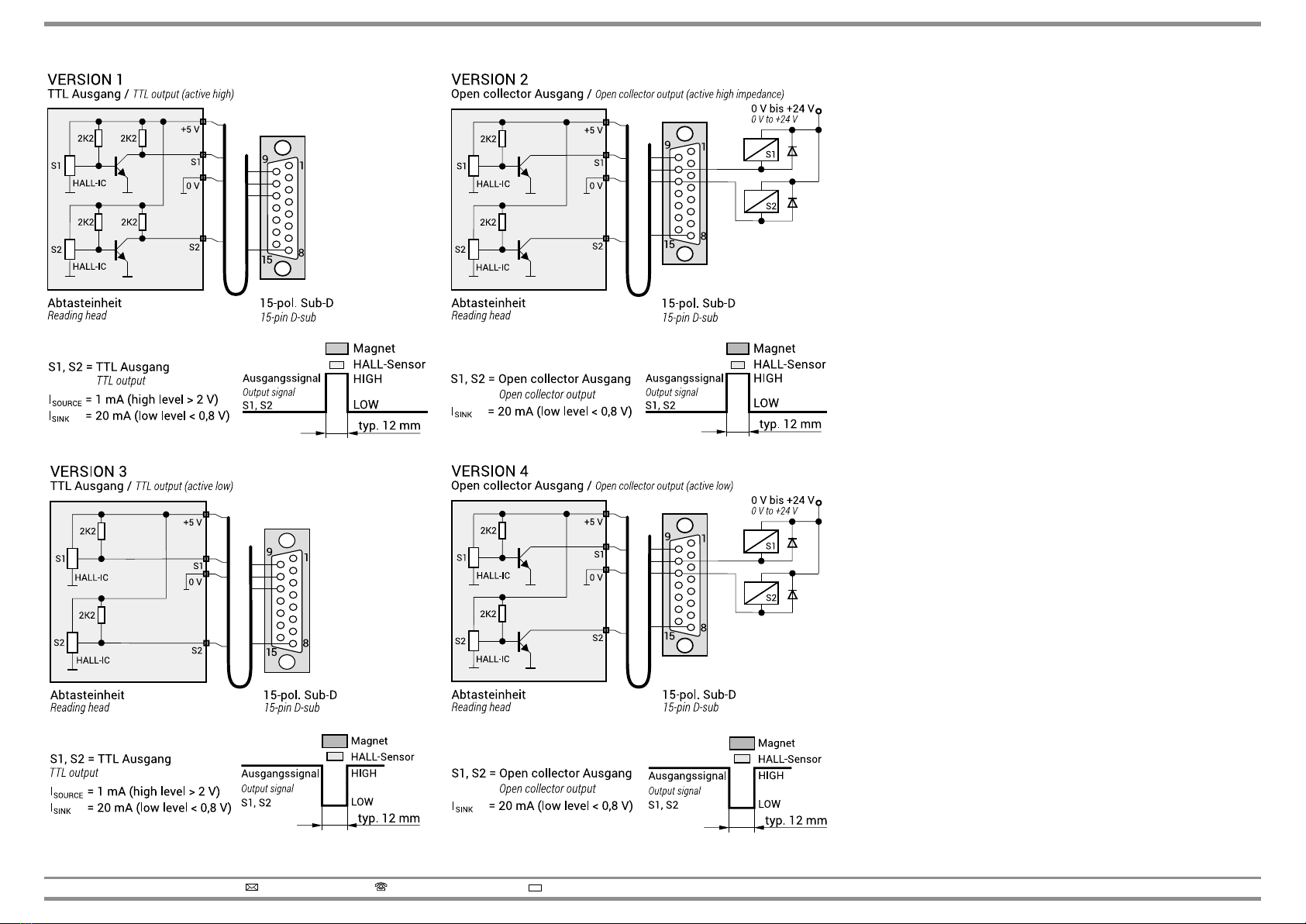
Schaltsignal Ausgang / Switch signal output Allgemeine elektrische Hinweise
General electrical information
Spannungsversorgung
Schließen Sie RSF Elektronik Messgeräte nur an Folge-Elektroniken an, deren Ver-
sorgungsspannung aus PELV-Systemen (EN 50 178) erzeugt wird.
RSFElektronikMessgeräteerfüllendieAnforderungenderNormIEC61010-1nur,wenn
die Spannungsversorgung aus einem Sekundärkreis mit begrenzter Energie nach
IEC 61010-13rd Ed., Abschnitt 9.4 oder mit begrenzter Leistung nach IEC 60950-12nd Ed.,
Abschnitt 2.5 oder aus einem Sekundärkreis der Klasse 2 nach UL1310 erfolgt.1)
1) Anstelle der IEC 61010-13rdEd., Abschnitt 9.4 können auch die entsprechenden Abschnitte
der Normen DIN EN 61010-1, EN61010-1, UL 61010-1 und CAN/CSA-C22.2 No. 61010-1 bzw.
anstelle der IEC 60950-12nd Ed., Abschnitt 2.5 die entsprechenden Abschnitte der Normen
DIN EN60950-1, EN60950-1, UL60950-1, CAN/CSA-C22.2 No. 60950-1 verwendet werden.
Voltage supply
Connect RSF Elektronik encoders only to subsequent electronics whose power supply
is generated from PELV systems (EN 50 178).
RSF Elektronik encoders fulll the requirements of standard IEC 61010-1 only if the
power is supplied from a secondary circuit with current limitation as per IEC 610103rd Ed.,
Section 9.4 or with power limitation as per IEC 60950-12nd Ed., Section 2.5 or from a
Class 2 secondary circuit as specified in UL1310.1)
1) In place of IEC 61010-1
3rdEd., Section 9.4, the corresponding sections of standards DIN EN
61010-1, EN61010-1, UL 61010-1 and CAN/CSA-C22.2 No. 61010-1 can be applied and in place of
IEC 60950-12nd Ed., Section 2.5 the corresponding sections of standards DIN EN60950-1,
EN60950-1, UL60950-1, CAN/CSA-C22.2 No. 60950-1 can be applied.
RSF Elektronik Ges.m.b.H. A-5121 Tarsdorf  +43 (0)6278 / 8192-0 
FAX
+43 (0)6278 / 8192-79  e-mail: [email protected]  Internet: www.rsf.at 06
Steckerbelegungen / Pin assignments
PIN-Belegung (Sicht auf Stiftseite)
Pin assignment (view on pins)
PIN-Belegung (Sicht auf Stiftseite)
Pin assignment (view on pins)
15-pol. Sub-D
15-pin D-sub
12-pol. M12-Rundstecker
12-pin M12-connector
Nach IEC 61076-2-101 LM012–Gxx-A
According to IEC 61076-2-101 LM012–Gxx-A
Sensor: Die Sensor-Pins sind im Steckergehäuse auf die jeweilige Spannungsversorgung gebrückt.
Sensor: The sensor-pins are bridged in the chassis with the particular power supply.
* Bei Ausführung ohne Schaltsignale (Version 0) = ohne Funktion.
Version without switch signals (version 0) = without function.
Schirm ist zusätzlich mit dem Steckergehäuse verbunden.
The shield is connected with the chassis.
* Bei Ausführung ohne Schaltsignale (Version 0) = ohne Funktion.
Version without switch signals (version 0) = without function.
Schirm ist mit dem Steckergehäuse verbunden.
The shield is connected with the chassis.
Pin 1 2 3 4 5 6 7 8 9 10 11 12 13 14 15
Spannungssignale
1 Vss
Voltage signals 1 Vpp
Belegt
Occu-
pied
0 V
Sensor
Weiß
White
Belegt
Occu-
pied
RI
Grau
Grey
A2
Rot
Red
A1
Gelb
Yellow
+5 V
Sensor
Schwarz
Black
+5 V
Schwarz
Black
0 V
Weiß
White
S1*
Orange
Orange
S2*
Violett
Violet
RI
Braun
Brown
A2
Rosa
pink
A1
Grün
Green
Schirm
Shield
Rechtecksignale
über Line Driver
Square-wave signals via
line driver
Belegt
Occu-
pied
0 V
Sensor
Weiß
White
US
Blau
Blue
RI
Grau
Grey
T2
Rot
Red
T1
Gelb
Yellow
+5 V
Sensor
Schwarz
Black
+5 V
Schwarz
Black
0 V
Weiß
White
S1*
Orange
Orange
S2*
Violett
Violet
RI
Braun
Brown
T2
Rosa
Pink
T1
Grün
Green
Schirm
Shield
Pin 1 2 3 4 5 6 7 8 9 10 11 12
Spannungssignale
1 Vss
Voltage signals 1 Vpp
+5 V
Schwarz
Black
A1
Gelb
Yellow
A2
Rosa
Pink
A2
Rot
Red
S2*
Violett
Violet
Belegt
Occupied
RI
Braun
Brown
RI
Grau
Grey
Belegt
Occupied
A1
Grün
Green
S1*
Orange
Orange
0 V
Weiß
White
Rechtecksignale
über Line Driver
Square-wave signals via
line driver
+5 V
Schwarz
Black
T1
Gelb
Yellow
T2
Rosa
Pink
T2
Rot
Red
S2*
Violett
Violet
US
Blau
Blue
RI
Braun
Brown
RI
Grau
Grey
Belegt
Occupied
A1
Grün
Green
S1*
Orange
Orange
0 V
Weiß
White
Schirmverbindungen / Shielding
Geschirmtes PUR-Kabel / Shielded PUR-cable.
Torsion > 300.000 Zyklen / Torsion > 300.000 cycles
Schleppkette >5.000.000 Zyklen
Dragchain > 5.000.000 cycles

Biegerad. einmalig / Bending rad. xed mounting
Biegerad. dauernd / Bending rad. continuous flexing
Abtasteinheit
Reading head
Schirm auf dem Gehäuse
der Abtasteinheit
Shield on housing of the reading head Stecker
Connector
*Steckerpin
*Connector pin
Schirm auf Gehäuse und Steckerpin
Shield on housing and connector pin
* Nur bei 15-pol. Sub-D
* Only with 15-pin D-sub

Other RSF Elektronik Media Converter manuals

RSF Elektronik MS 25 User guide

RSF Elektronik

RSF Elektronik MS 25 User guide

RSF Elektronik MSA 871 User manual

RSF Elektronik

RSF Elektronik MSA 871 User manual

RSF Elektronik AK MS 15 User manual

RSF Elektronik

RSF Elektronik AK MS 15 User manual

RSF Elektronik MS 25 MA User manual

RSF Elektronik

RSF Elektronik MS 25 MA User manual

RSF Elektronik MS 45 MO User manual

RSF Elektronik

RSF Elektronik MS 45 MO User manual

RSF Elektronik MSA 771 User manual

RSF Elektronik

RSF Elektronik MSA 771 User manual

RSF Elektronik AK MSS 25 1 Vss User manual

RSF Elektronik

RSF Elektronik AK MSS 25 1 Vss User manual

RSF Elektronik MSA 820 User manual

RSF Elektronik

RSF Elektronik MSA 820 User manual

Popular Media Converter manuals by other brands

Musical Fidelity M1 DAC Instructions for use

Musical Fidelity

Musical Fidelity M1 DAC Instructions for use

Ikegami IDE-10 instruction manual

Ikegami

Ikegami IDE-10 instruction manual

SMSL M400 user manual

SMSL

SMSL M400 user manual

Converters.TV 479 Operation manual

Converters.TV

Converters.TV 479 Operation manual

IMC Networks IE-MiniFiberLinX-II Operation manual

IMC Networks

IMC Networks IE-MiniFiberLinX-II Operation manual

YOKOGAWA JUXTA VJP8 user manual

YOKOGAWA

YOKOGAWA JUXTA VJP8 user manual

gefran SieiDrive EXP-FIH instruction manual

gefran

gefran SieiDrive EXP-FIH instruction manual

Hubner FGH 6 Operating and assembly instructions

Hubner

Hubner FGH 6 Operating and assembly instructions

CYP CDPS-US100R Operation manuals

CYP

CYP CDPS-US100R Operation manuals

evertz 2405EO instruction manual

evertz

evertz 2405EO instruction manual

Plextor ConvertX PX-AV100U Installation and user manual

Plextor

Plextor ConvertX PX-AV100U Installation and user manual

DCS LDT-M1 user manual

DCS

DCS LDT-M1 user manual

Belden Grass Valley SME-1901 Guide to installation and operation

Belden

Belden Grass Valley SME-1901 Guide to installation and operation

Videon Shavano product manual

Videon

Videon Shavano product manual

Niveo NMC1000 user guide

Niveo

Niveo NMC1000 user guide

CHIYU CYT-200SC user manual

CHIYU

CHIYU CYT-200SC user manual

ADF Web HD67B23-B2 user manual

ADF Web

ADF Web HD67B23-B2 user manual

ADS Technologies API-550 user guide

ADS Technologies

ADS Technologies API-550 user guide

manuals.online logo
manuals.online logoBrands
  • About & Mission
  • Contact us
  • Privacy Policy
  • Terms and Conditions

Copyright 2025 Manuals.Online. All Rights Reserved.