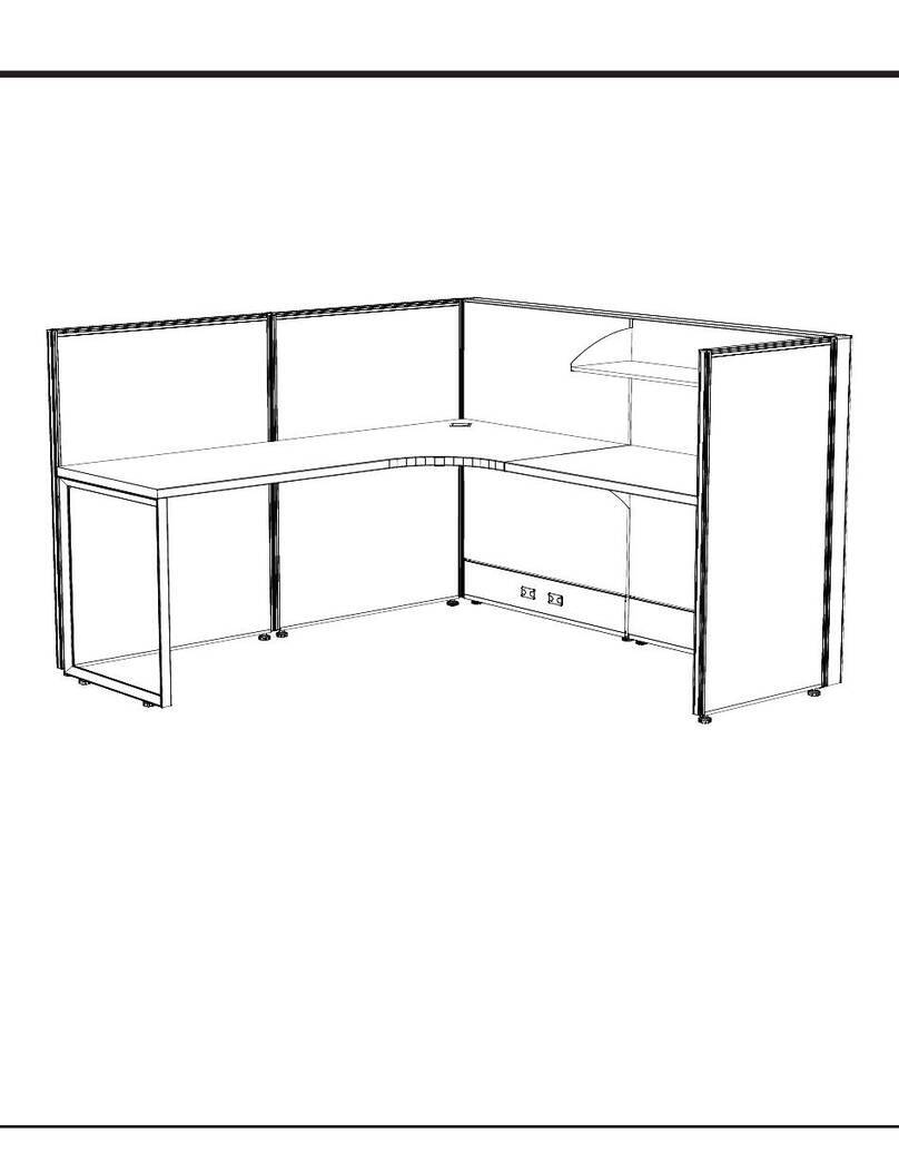
RSI Systems Furniture EZcube User manual

RSI Systems Furniture
EZcube Installation Guide

RSI Systems Furniture
2

3
RSI Systems Furniture
EZcube Installation Guide
4-6
7-8
9
10-11
12-13
14-15
16
17
18-19
20
21
22
23
24-27
28
29
X31 Connection Post
Panel-to-Panel
X3 Connection Post
Topfeed
X1 Connection Post
End Trim
X3 Top Cap
Shelf
Worksurface Supports
Support Leg
Power Block
Duplex
Panel Jumper
Basefeed
Light Blocking Strips
Frameless Glass

STEP 2: Determine which side of the panel has CON-A and
CON-B
STEP 1: Lift up and remove the fabric tile from one side of
the panel.
CON-B
(Non-Threaded Connector
CON-A
(Threaded Connector)
4RSI Systems Furniture
X3 Panel to X31 Post

STEP 3: Align X31 Post to X3 Panel Rail,
push your X31 Post Screw through
the CON-B and screw the pole into
the post. See Photo above for proper
alignment instructions.
X3 Panel to X31 Post
5
RSI Systems Furniture
See arrow above. Bottom of post top
cap should line up with top of side rail.
CON-B
(Non-Threaded Connector)
M8 X 20mm
X31 Post Screw
NOTE: If you have Con-A mounted inside the
panel you will need to ip the panel around or
swap brackets out with extra Con-B brackets
that are included in your hardware pack.

STEP 3: Lift up slightly on the panel to ensure the panel
and post are locked together.
The top of the X1 panel should line up with the top of the
X31 post.
STEP 2: Lift up the panel you are connecting and lower
in on to the interlocking brackets of the X31 Post you are
connecting to.
When lowering it onto the post you should hear the X1
Panel Lock click.
RSI Systems Furniture
X1 Panel to X31 Post Connection
6
STEP 1: Determine the direction of the interlocking
brackets on each side of the panel.
NOTE: Every X1 panel has a spring loaded panel lock
already installed.
X1 Panel Lock
X1 Panel Lock

7
RSI Systems Furniture
X3 Panel to Panel
STEP 1: Grab your X3 Panel Screw (M8x30mm), stick it
through CON-B and start screwing it into CON-A that is
mounted inside the panel you are connecting to.
STEP 2: Before fully tightening the screw make sure the top
and sides of the panels are aligned.
Con-B
(Non-Threaded Connector
Con-A
(Threaded Connector)
M8 X 30mm
Panel Screw

RSI Systems Furniture
X1 Panel to Panel
8
STEP 1: Determine the direction of the interlocking
brackets on each side of the panel.
Side-2
Side-2
Side-1
Side-1
STEP 2: Lift up the panel you are connecting and slide Side-1 onto the interlocking brackets of Side-2. You should
hear the locking bracket click into place once Side-1 is completely seated on Side-2.
NOTE: Every X1 Panel connection should be locked into place with an X1 Panel Lock

9
RSI Systems Furniture
X3 Connection Post
STEP 3: Make sure the bottom top cap line on the
X3 Post lines up with the top of the side rail then n-
ish tightening the screw.
STEP 2: Feed your X3 Ponel Screw (M8x30mm) through the
CON-B bracket and into the post.
NOTE: If you have CON-A mounted inside the panel you will
need to swap them out with the extra CON-B brackets that
are included in your hardware pack.
STEP 1: Fit the X3 Post Centering Pieces
into the X3 Panel Rail.

RSI Systems Furniture
X3 End-of-Run TFM
10
STEP 2: Feed your X31 Post Screw (M8x20mm) through the CON-B bracket and
into the post.
NOTE: If you have CON-A mounted inside the panel you will need to swap
them out with the extra CON-B brackets that are included in your hardware
pack.
NOTE: TFM whips plug directly into the end of the power block. If you receive a
180” whip with a 10’ pole you will jump a panel before plugging the TFM whip
into the power block.
STEP 1: Fit the X3 TFM Centering Pieces into the X3 Panel Rail.

11
RSI Systems Furniture
X3 2-way / 3-way TFM
STEP 2: Feed your X31 Post Screw (M8x20mm) through the CON-B bracket and
into the post.
NOTE: If you have CON-A mounted inside the panel you will need to swap
them out with the extra CON-B brackets that are included in your hardware
pack.
NOTE: TFM whips plug directly into the end of the power block. If you receive a
180” whip with a 10’ pole you will jump a panel before plugging the TFM whip
into the power block.
STEP 1: Fit the X3 TFM Centering Pieces into the X3 Panel Rail.

RSI Systems Furniture
X1 2-Way Post
12
STEP 2: Unscrew the X1 connecting brackets and slide up and off the panel.
STEP 3: Flip connecting brackets and reinstall pointed in the downward direction along with an added locking bracket at
the top as it is shown above. Extra X1 Locking Brackets located in your hardware pack.
STEP 4: Ensure your connecting brackets are in the same position as shown above so it properly locks to the X1 Connection
Post. If installed correctly it should match the opposite side of the panel and should have two locking brackets installed on
the same panel.
STEP 1: Remove the X1 Panel Side Top Cap
BEFORE AFTER

13
RSI Systems Furniture
X1 2-Way Post
STEP 6: Position X1 Connection Post
against the panel that you just ipped
the connecting brackets on and add-
ed the additional locking bracket.
STEP 5: Grab your X1 Connection Post
and position it as shown above. Notice
the connecting brackets should be
pointed in the same upward direction.
STEP 8: Grab your next X1 Panel and install it as you normally would on any other X1
Panel. Listen for the locking bracket to click into place to ensure a solid connection
STEP 7: Slide X1 Connection Post up-
ward until you hear the locking bracket
click into place.

RSI Systems Furniture
14
X3 End Trim
STEP 2: Push the end trim against the panel starting
from the top.
Note: You should hear it start to click into place as
you center it all the way down the panel.
STEP 1: Line up the top of the end trim
with the top of the side rail.
STEP 3: Hold end trim against the panel
rmly then slowly screw end trim into place
using the self tapping X3 End Trim screws
provided.
Note: Do not over tighten screws. This will
cause the screws to strip out and not hold
the end trim properly
STEP 4: To connect the corner transition, rst place the
fabric tile on the panel then insert the corner transition
into the top cap and press the top cap down onto the
panel.
Note: For top cap installation instructions see page-16

15
RSI Systems Furniture
X1 End Trim
STEP 2: Unscrew the X1 connecting brackets then
slide the brackets up and off the panel
STEP 3: Insert the X1 End Trim by either sliding it down from the top or snap-
ping it in from the side as shown above.
STEP 1: Remove the X1 Panel Side Top Cap

16 RSI Systems Furniture
X3 Top Cap
STEP 1: Snap the top cap down at an an-
gle in one of the corners to get it started.
Before installing the top cap make sure you install
the fabric tile back on the panel.
STEP 3: Make sure that the bottom of the
top cap is completely seated against
the top of panel.
Never use a hammer or mallet on top caps
STEP 2: Slowly move down the panel and
snap it into place as you move down to
the end.

17
RSI Systems Furniture
X3 Low Shelf
STEP 1: Install the shelf ends to the bottom shelf pan with the screws provided in your
hardware pack.
STEP 2: Angle the shelf and insert the top tooth into the side
rail.
STEP 3: Make sure the shelf is completely seated on the side
rail
M6 X 12mm
X3 Shelf Screw

RSI Systems Furniture
X3 Support Brackets
18
STEP 1: Angle the work surface bracket and insert the top tooth into
the Side Rail
STEP 2: Make sure the bracket is completely seated on the side rail
NOTE: The top of the brackets should be installed around 28.5”

19
RSI Systems Furniture
X1 Support Brackets
STEP 4: Slide the loose X1 Cantilever Connection Bracket down the side rail slot with the cantilever
attached. Tighten the screws once you have reached the correct height.
STEP 3: Measure the height on the X3 work surface brackets so
you know what height to tighten the brackets at.
STEP 2: Locate your hardware pack and get the X1 Brack-
et Screws and X1 Cantilever Connection Bracket. Push screws
through the cantilever and screw them in a little bit into the X1
Cantilever Connection Bracket. (do not tighten yet)
STEP 1: Remove X1 Panel Side Top Cap
X1 Cantilever Connection Bracket
X1 Bracket Screws

RSI Systems Furniture
Front Edge
Support Leg
STEP 1: Position the leg so it is ush with the front corner edge
of the surface.
STEP 2: Attach one screw to the bottom side of the surface. This
will provide additional support while you attach the surface to
the corner bracket that will be positioned behind the leg.
STEP 3: Slide the leg over and attach the corner bracket to the worksurface.
NOTE: The support leg should be ush with the end of the panel so it covers up the support bracket
STEP 4: Slide the leg back to its original loca-
tion and attach the remaining screws.
20
Other manuals for EZcube
2
Table of contents
Other RSI Systems Furniture Indoor Furnishing manuals
Popular Indoor Furnishing manuals by other brands

RiverRidge
RiverRidge 16-031 Assembly instructions

Costway
Costway JV10691 Instruction booklet

Pulaski Furniture
Pulaski Furniture A947T-305-1290 Assembly instructions

Case
Case Tanso 107738 quick start guide

Fif Möbel
Fif Möbel Toro-4 Assembly instruction

Furniture of America
Furniture of America FGI-2070C21 Assembly instructions

Furniture of America
Furniture of America CM3882PC - 2PK Assembly instructions

Hailey Home
Hailey Home CT1682 Assembly instructions

Rauch
Rauch M2094 Assembly instructions

Triarch
Triarch Indoor Lighting 33232 Assembly instruction

aspenhome
aspenhome I597-9100 Assembly instructions

Aqua Creek Products
Aqua Creek Products SPA LIFT ULTRA manual