RST TITAN Series User manual

KILLAH
STITCH
STORM
ROGUE
RENEGADE
TITAN series
CHAMP series
F1RST series
AERIAL series
PULSE series
SPACE
VOGUE
VIVAir
GUIDE
ENGLISH

XC1800-122
RST Greenergy Tech. Co., Ltd.
886-4-2681-5725
886-4-2681-5752

OWNER’S MANUAL 1
CONGRATULATIONS on selecting an RST suspension fork.
You have chosen the best suspension components for your
bicycle! This RST fork is fully assembled and ready to be
installed onto your bicycle.
ENGLISH

2
Proper care and maintenance of your RST product is necessary for longevity and optimum
performance.
Failing to perform routine maintenance will greatly decrease the performance of the
product and may lead to premature deterioration or even failure of the product. Lack of
maintenance may also jeopardize the safe operation of your fork and will void the warranty.
This is an off-road fork, and as such, does not come with proper reectors for on-
road use.
Have your dealer or mechanic install proper reectors to meet the Customer Product
Safety Commission’s (C.P.S.C.) requirements for bicycles if the fork is going to be
used on public roads at any time.
This manual contains important information about the safe operation and maintenance
of your fork. Reading this manual entirely, and properly maintaining your bicycle and
suspension fork is essential. To ensure that your RST fork performs properly, we
recommend that you have your fork installed by a qualied bicycle mechanic. Prior to
riding your bicycle, you should inspect your suspension fork to ensure that no damage
has occurred during the course of riding.
Do not ride your bicycle if the fork shows any signs of bending, cracking, leaking, or
if it is missing any of the original supplied components. Any fall from your bicycle can
result in serious injury or even death. Following these instructions can help you reduce
the risk of being injured. We recommend returning your suspension fork to your dealer
or an authorized service center annually for a thorough inspection and service.
1. Never remove or have the steerer tube or stanchions removed from the crown. The
steerer tube and stanchions (inner legs) are press t at the factory. Press tting of the
inner legs and steerer tubes has higher performance versus having clamped stanchions
or steerer tubes, but they can NOT be pressed out and changed. Pressing them out will
permanently damage the crown beyond repair and render it unsafe for any use.
2. Do NOT attempt to thread a thread-less steerer tube. Cutting threads will weaken the
steerer tube and cause an unsafe condition. The only safe thing to do is to obtain the
proper crown/ steerer from your dealer, contact RST USA warranty service center or
RST Europe.
3. Any other alteration or modication to your fork should be considered unsafe and will
void the warranty. Contact your dealer, RST USA warranty service center or RST Europe
prior to modifying your fork in any way for safety information.
4. Do not use an RST fork if any parts are broken, bent, cracked, or you suspect may be
damaged. Contact your dealer, RST USA warranty service center or RST Europe, if you
have any question concerning the integrity or condition of your fork.
5. RST recommends that you inspect your fork before every ride for wear and damage.
Please pay particular attention to the crown, stanchions, sliders, dropouts and brace for
any sign of cracks, bending or damage.
CAUTION
IMPORTANT
GENERAL WARNING
CONSUMER SAFETY INFORMATION

OWNER’S MANUAL 3
Any RST fork found, by the factory, to be defective in materials and/or workmanship
within two year from the date of purchase will be repaired or replaced at the option of the
manufacturer, free of charge, when received at the factory with proof of purchase, freight
prepaid. This warranty does not cover any fork that has been subject to misuse or abuse,
including but not limited to, any breakage, bending, damage cause by crashes and/or
assembly, improper maintenance, or other excessive, improper or abnormal conditions.
This warranty does not cover paint damage.
Any modications or alterations made by the user will render the warranty null and void.
This warranty is expressly in lieu of all other warranties, and any implied are limited
in duration to the same duration as the expressed warranty herein. RST shall not be
liable for any incidental or consequential damages. In the event that a product needs to
be replaced and is discontinued or not available, RST reserves the right to replace the
product with one of equal value, no credit or refund will be issued.
This product is not intended for use in stunt or acrobatics riding, ramp jumping, or similar
activities, the user assumes all risks of personal injury, product damage or failure, and any
other losses which may arise under such use.
If for any reason, warranty work is necessary, return the fork to the place of purchase, In
the USA and Canada, dealers should call RST USA warranty service center. Customers in
countries other than USA should contact their local dealer or distributor or RST Europe.
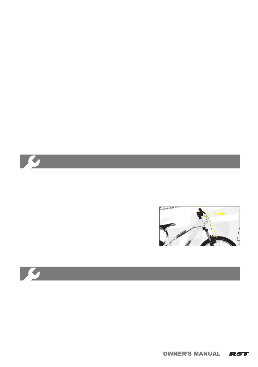
It is extremely important that your RST fork is installed correctly by a qualified bicycle
mechanic. Improperly installed forks are extremely dangerous and can result in serious
and/or fatal injuries. Ensure that the proper steerer tube has been delivered on your RST
fork. The steerer tube may need to be cut to length to t your bicycle head tube. If you
are not familiar with this procedure, or do not have proper tools to cut the steerer tube,
it is recommended that you seek a dealer with a qualied bicycle mechanic to perform
installation.
1. Remove the old fork from your bike.
2. Measure the length of steerer tube to t your bicycle head tube, make sure there is
sufcient length to install the stem (refer to the stem manufacturer’s instructions), you
can use your old fork as guide for cutting the length of steerer tube.
WARRANTY INFORMATION
INSTALLATION INSTRUCTION
The steerer tube and stanchions (inner legs) are a one-time precision press t at the
factory and can not be removed from the crown. Replacement of the entire crown/
steerer assembly must be done to change steerer tube lengths or diameters.
Attempting to remove and replace the steerer tube or stanchions will result in an
unsafe condition and should never be done.
WARNING
FORK INSTALLATION

4
Before every ride, please perform the following inspection:
1. Ensure that quick release skewers and thru axles are properly adjusted and tight.
2. Wipe the stanchions and outer legs clean and check entire fork for any obvious damage.
3. Check the headset for proper adjustment.
4. Ensure that the front brake cable is properly routed and check brake adjustment.
Whenever the performance of the fork is noticed to have diminished or it has reached
a service interval (whichever occurs rst), perform the following procedures:
SAFETY MAINTENANCE
PERFORMANCE MAINTENANCE
3. Install the headset crown race (as per manufacturer’s instructions) rmly against the
top of the fork crown.
4. Clean and lubricate the headset bearings and races.
5. Insert the steerer tube into the head tube of the frame.
6. Install the upper bearings, stem spacers, and stem.
7. Install the stem cap and bolt. Tighten the bolt to headset manufacture’s specications.
8. Install the handlebars to desired height and torque stem pinch screws or stem
clamping system to manufacturer’s specications. Adjust the headset until you feel no
play and drag.
9. Install the brakes and adjust per manufacturer’s instructions.
10. Install the front wheel into the dropout counter bore. The quick release must be
tightened after it is properly seated into the dropout counter bores to manufacturer’s
specications.
11. Make sure to check the tire clearance. To check tire clearance, remove the air
pressure and/or spring stacks and compress the fork completely to make sure a
minimum of 1/4’’ (6.4mm) of clearance exists between the top of the tire and the
bottom of the crown.
12. Your new fork is designed to break-in during your rst few rides (about 20 hour total
riding time). Prior to break-in, you may notice your fork feels tight and slightly sluggish.
Following the break-in period, your fork will feel much smoother and will react to
bumps much better than when you rst put in on your bike.
1. Disassemble fork and thoroughly clean grease and residue from each part.
2. Inspect all parts for damage such as cracks, abrasions, and normal wear. If any parts
are found to be damaged or excessively worn in anyway, replace them immediately.
Stop using this product until the damaged or worn parts have been replaced. If all the
parts are in usable condition, proceed to step 3.
3. Apply a liberal amount of approved grease to the upper and lower bushing, stanchion,
valve assembly, and wipers. Fill the wiper pocket with a generous amount of grease.
Do not use a lithium grease as it can cause damage to the bushing material and the
seals.
5. Check top caps, brake posts and shaft bolt for
proper torque.
6. Please pay particular attention to ensure that
steerer and stanchion tubes are still parallel.
(Bending of the fork forward or backward is a
common trait of hard landings.)

OWNER’S MANUAL 5
1.For forks with the crown-mounted compression adjuster, rotate the
2.For forks with the remote lever adjuster, press the lever
FUNCTION
Replacing bushing requires special tools to remove and install the bushings properly.
RST strongly recommends this work should be done by a qualied mechanic with the
proper tools. Improperly installed bushings are extremely dangerous and can result
in serious and/or fatal injuries.
IMPORTANT
Suggested service intervals for all RST suspension forks
Normal Conditions Severe Conditions
Short Sporadic Rides Long Frequent Rides Short Sporadic Rides Long Frequent Rides
Every 6 months Every 4 months Every 4 months Every 3 months
Suggested replacement/service intervals of wear and tear parts as
follows
Dust seal 6 months Rear shock mounting 1 year
Air sealing O-ring 1 year Remote lockout cable 1 year
Rubber moving parts 1 year Lubricant--grease 6 months
Normal wear and tear parts are identied as follows
1 Dust seal 6 Remote lockout cable
2 Air sealing O-ring 7 Bushing
3 Rubber moving parts 8 Stanchion (upper tube)
4Rear shock mounting
hardand main seal 9 Pivot
5 Strippeds/bolt 10 Lubricant-grease
adjuster counterclockwise to change the amount of compression
damping to the lockout.
down to change the amount of compression damping to
the lockout. Note: For more detail installation tips for the
TRL or for help in troubleshooting any problems in TRL
adjustments, please log on to the RST website (www.rst.
com.tw) for relative information.
Bushing replacement:
In the event that an RST fork is founded to have excessive play between the stanchion
and outer leg, the bushings will need to replaced.
All forks, that have been 5 years or more, should be inspected and serviced annually if
they are going to remain in use.

6
3.Rotate the rebound adjuster as indicated on the sticker to adjust
4.Note: A minimum amount of fork movement (0~15mm) could
Tiny Remote Lockout Assembly
The TRL lever is the smallest, lightest, multi-setting remote lever RST has ever offered.
The interchangeable release button allows the rider to choose the optimum position of
the TRL lever on either side of the handle bar.
Instruction for the TRL assembly:
1. Choose the release lever position once you found
the optimum side on the handle bar for the lever
2. Unscrew the release button and take out the spring,
alloy washer and xing bolt
3. Put in the bolt first, then the alloy washer and the
spring before tightening the release button
4. Tighten the open clamp with 2.5Nm maximum
the rebound faster or slower.
appear when the fork is in the lockout position. This is normal in
the design of the fork.
Rebound adjustment
Hydraulic damping system with external rebound adjustment.
1. Rotate the rebound adjuster clockwise to increase the rebound
damping and turn it counterclockwise to decrease the rebound
damping.
2. Turn the adjuster knob then test the fork to make sure the rebound
damping can meet your requirement. If not, try another 1/2 turn.
Air spring system
RST air spring system provides the positive air chamber and negative coil spring to
make the fork lightweight and allows for easy air pressure set up.
The Air system is a built-in type and it needs to be adjusted according
to the different needs and desires of different riders. Consult the table
below to select the air pressure that is the best for you.

OWNER’S MANUAL 7
FIRST Platinum
Rider-Weight(kg)
Pressure(Psi)
40-60
50-70
60-80
70-90
80-100
90-110
100-110
110-120
110-120
140
VOGUE
Rider-Weight(kg)
Pressure(Psi)
40-60
110
60-80
115-120
80-100
120-130
100-110
130-140
110-120
140-150
Rider-Weight(kg)
Pressure(Psi)
40-60
60
60-80
60-80
80-100
80-100
100-110
100-120
110-120
120-150
STITCH, SPACE Jump
Rider-Weight(kg)
Pressure(Psi)
20-40
30-40
40-60
35-40
60-80
45-55
80-100
55-65
100-120
120
RECOMMENDATION FOR AIR PRESSURE
Mechanical Lock-out
Lock-out situation:
Lock the fork easily and rapidly by any travel.
Remote Lockout
Hydraulic Remote Lock-out’’ system which provide an
easy way to use lock-out function from handle bar.
Hydraulic Lock-out
Lock-out situation:
By using lever to adjust the fork’s compression from fast to slow
gradually, then till lock-out position in the end.
AERIAL series, VIVAir, PULSE AIR series
ROGUE, GUIDE,RENEGADE, TITAN/ TITAN 15, CHAMP series,
F1RST series,

8
SAG is the amount of suspension fork travel that rider sits on the bicycle
without use any force on it. The SAG can help to maintain contact and
traction over bumpy terrain.
MEASURING AND SETTING SAG
INCREASE AIR PRESSURE
1. Unscrew the valve cap on the left leg and set aside.
2. The air tting is of the Schrader valve type.
3. Use the RST air pump, to pressurize the fork to the desired level. (Upon removing
the air pump, there may be some air lost. This is air escaping from the pump and
doesn’t affect the pressure setting you set the fork at).
4. To decrease pressure, it is best to use the RST air pump since the air chamber
volume is quite small and will allow better control than simple depressing the
center pin of the Schrader valve.
WARNING
Changing the suspension settings on the fork can change the handling and braking
characteristics of your cycle. Do not change the adjustment until you are fully familiar
with the instructions and recommendations. Always check for changes in handling or
braking by taking a careful test ride in a safe environment after each adjustment.
LUBRICATION
To ensure the fork’s optimum performance, we recommend regular lubrication with
a suspension approved grease. Please log on RST website (www.rst.com.tw) for
maintenance manual information.
NOTE: Since all air chambers contain a small amount of oil, you should only
adjust the air pressure with the fork in an upright position. If you depress the
Schrader valve manually, it is normal to see a small amount of oil mist, please
use a shop towel to cover the valve to protect yourself and do not look directly
over the valve.
Zip-tie method
1. Please install a zip tie down against the wiper seal
of the fork’s stanchion and without the rider on the
bicycle.(see as photo1)
2. Sit on the bicycle in a normal riding position. RST
recommends that you to t up with your normal riding
equipment. It may be necessary to hold yourself up
against the wall to help steady yourself. Do not bounce on pedals or saddle.
3. Step off the bicycle and measure the distance between the zip tie and wiper seal. This
is the sag value. RST recommends the proper value of sag should be between 15 and
25 percent of maximum travel. If the distance shorter than the 15 percent of maximum
travel. It means the fork is too stiff (You need to decrease the air pressure). If the
distance longer than the 25 percent of maximum travel. It means the fork is too soft (You
need to increase the air pressure).
4. For Air pressure setting of all air forks, please refer to the next paragraph ‘’INCREASE
AIR PRESSURE’’.

OWNER’S MANUAL 9
MAX. RECOMMENDATION ROTOR SIZE
MODEL NAME TYPE ROTOR SIZE
POST 203(mm)
SPACE IS 203(mm)
RENEGADE POST 180(mm)
POST 180(mm)
CHAMP series POST 180(mm)
F1RST series POST 180(mm)
AERIAL series POST 180(mm)
PULSE series POST 180(mm)
VOGUE IS 180(mm)
VIVAir IS 180(mm)
SPECIAL INSTRUCTION FOR 20MM HUB AND QR
INSTALLATION
Installing 20mm Front Hub
1. Slide hub (including 20mm cones) into the legs and line up with axle holes.
2. Apply grease or Anti seize to the entire 20mm axle.
3. Slide the 20mm Axle into the fork/hub from the left hand side (Disc side).
4. Gently turn the axle clockwise to connect to the axle threads in the right hand leg.
5. Once located V fully tighten the axle to 12-15Nm using an 8mm Hex key.
6. Apply grease or anti seize to the Right Hand side Axle lock bolt.
7. Gently screw-in the lock bolt into the 20mm axle end.
8. Hold the left hand side of the axle with a 8mm Hex key and fully tighten the right hand
side lock bolt to 12-15Nm using a 2nd 8mm Hex Key.
9. Check that Disc brake operates correctly.
Instruction of disassemble 20mm thru axle:
1.Use 8mm allen key to loose the bolt in the right leg.
2.Use 8mm allen key to loose the 20mm thru axle.
WARNING
1. Before disassembly of the ‘’function system’’, it is strongly recommended to
take it to an RST dealer. The authorized RST dealers will provide qualified
technicians with proper tools and training to perform service correctly. Improper
disassembly may damage the product and lead to failure of human injury.
2. Before completing maintenance, please make sure all screws have been
securely tightened according the correct torque settings to avoid any human
injury.
TITAN15/ TITAN
KILLAH/ STITCH/STORM
/ ROGUE/ GUIDE

10
15QR: 15mm Aluminum Quickly Release axle
1. Slide hub into the legs and line up with axle holes.
2. Apply grease or Anti seize to the entire 15mm axle.
3. Slide the 15mm Axle into the fork/hub from the left hand side (Disc side).
4. Gently turn the axle clockwise to connect to the lock bolt threads in the right hand leg.
5. Turn the 15QR axle to the xed position; tighten the 15QR axle to 15Nm by press the
lever.
6. If need to adjust the lever position of the 15QR axle, pull open the lever of 15QR axle
then remove the grub screw then adjust the lock bolt with 15QR axle to the proper
position.
7. 7.Install the grub screw into the ‘’location dimples’’ of the lock bolt, tighten the 15QR
axle to 15Nm by press the lever again. (Taking care to keep the ‘’location Dimples’’ in
line with the grub screw hole in the fork. You should be able to see the location Dimple
by looking down the hole.
8. Check that Disc brake operates correctly.
Installing QR type Front Hub
1. Identify Adaptor and parts
2. Carefully install grub-screws 3 turns into fork legs-ensuring they are not cross-
threaded. (Note: this may initially be harder than normal, as grub screw may have to
clear some paint residue in the threads from the leg.)
3. Remove the grub-screws.
4. Lightly grease the outside of the adaptors.
5. Install the right hand adaptor into the Right hand leg, taking care to keep the ‘’location
dimples’’ in line with the grub screw hole in the fork. You should be able to see the
location dimple by looking down the fork leg hole.
6. Install the grub screw and tighten gently until it contacts the adaptor.
7. Back-out the grub screw 2 full turns, and the gently try to turn the adaptor.
You should feel a small amount play, between the grub screw head and the adaptor ‘’location
dimple’’-and your small turn should be stopped by the grub screw. If your rotation is not
stopped, it means the grub screw head is not entering the ‘’location dimple’’. Retry. Once you
are convinced that the grub screw is lined up with the ‘’location dimple’’ you can fully tighten
the grub screw to 3Nm.
SAFETY NOTE: It is IMPORTANT that the grub screws are correctly located into the adaptor
dimples ‘’IF NOT’’ the adaptors could rotate and cause a failure.
8. Repeat with Left Hand Adaptor.
SPECIAL INSTRUCTION FOR 15MM QR AXLE INSTALLATION
This manual suits for next models
13
Table of contents
Other RST Bicycle Accessories manuals