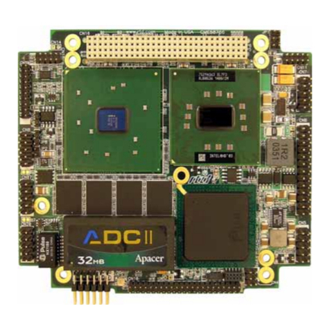
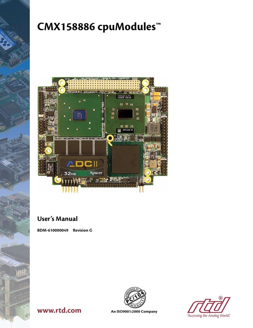
rtd CMV6586DX133 User manual

CMV6586DX133,
CMV6486DX100HR, and
CMV6486DX66HR
cpuModuleTM User’s Manual
BIOS Versions 4.7x
BDM-610000002
Rev. A
www.rtdusa.com
(Real Time Devices)
I
IS
SO
O9
90
00
01
1
a
an
nd
d
A
AS
S9
91
10
00
0
C
Ce
er
rt
ti
if
fi
ie
ed
d


CMV6586DX133, CMV6486DX100HR,
and CMV6486DX66HR cpuModuleTM
User’s Manual
RTD Embedded Technologies, INC.
103 Innovation Blvd.
State College, PA 16803-0906
Phone: +1-814-234-8087
FAX: +1-814-234-5218
E-mail
sales@rtd.com
techsupport@rtd.com
web site
http://www.rtd.com

Revision History
Rev. A) New manual naming method
Published by:
RTD Embedded Technologies, Inc.
103 Innovation Blvd.
State College, PA 16803-0906
Copyright 1999, 2002, 2003 by RTD Embedded Technologies, Inc.
All rights reserved
Printed in U.S.A.
The RTD Logo is a registered trademark of RTD Embedded Technologies. cpuModule and utilityModule
are trademarks of RTD Embedded Technologies. PhoenixPICO and PheonixPICO BIOS are trademarks of
Phoenix Technologies Ltd. PS/2, PC/XT, PC/AT and IBM are trademarks of International Business Ma-
chines Inc. MS-DOS, Windows, Windows 95, Windows 98 and Windows NT are trademarks of Microsoft
Corp. PC/104 is a registered trademark of PC/104 Consortium. All other trademarks appearing in this doc-
ument are the property of their respective owners.

Chapter1: Introduction .................................. 7
The CMV6x86DX cpuModules ........................................................8
Specifications ....................................................................................10
Chapter2: GettingStarted................................ 13
Basic Connector Locations ...............................................................14
Cable Kits .........................................................................................16
Connecting Power .............................................................................17
Connecting the utility cable ..............................................................18
Connecting a Keyboard ....................................................................19
Connecting to the PC/104 Bus ..........................................................20
Booting the cpuModule for the First Time .......................................21
Default Configuration .......................................................................22
Booting to Boot Block Flash with Fail Safe Boot ROM ..................23
If You Misconfigure the cpuModule ................................................24
For More Information .......................................................................25
Chapter 3: Connecting the cpuModule . . . . . ................. 27
I/O Connections ................................................................................28
Connector Locations .........................................................................29
Auxiliary Power, CN3 ......................................................................30
First Serial Port, CN7 ........................................................................31
Second Serial Port, CN8 ...................................................................34
Parallel Port, CN6 .............................................................................37
Multifunction Connector, CN5 .........................................................39
PC/104 Bus, CN1 and CN2 ..............................................................41
PC/104 Bus Signals ..........................................................................43
Chapter 4: Configuring the cpuModule . . . . ................. 47
Configuring Hardware ......................................................................48
Installing SSD Memory ....................................................................50
Configuring with the BIOS Setup program ......................................53
Chapter 5: Using the cpuModule ........................... 61
Memory Map ....................................................................................62
Input/Output Address Map ...............................................................63
Hardware Interrupts .........................................................................65
The BIOS ..........................................................................................66
Power On Self Tests (POSTs) ..........................................................67
Default Configuration .......................................................................69
BIOS Routines for Hardware Control ..............................................71
EEPROM Control .............................................................................72
Watchdog Timer Control ..................................................................75
Direct Hardware Control ..................................................................76
Storing Applications On-board .........................................................80
Using Virtual Devices .......................................................................89
Utility Programs ................................................................................94
Chapter 6: Hardware Reference ........................... 99
Jumpers .............................................................................................100
Solder Jumpers ..................................................................................104
Mechanical Dimensions ....................................................................105
486DX100/66 Processor Thermal Management ..............................106
5x86DX133 Processor Thermal Management .................................107
Chapter7: Troubleshooting............................... 109
Common Problems and Solutions .....................................................110
Troubleshooting a PC/104 System ...................................................113
How to Obtain Technical Support ....................................................114
How to Return a Product ..................................................................115
Chapter8: LimitedWarranty ............................. 117

CHAPTER 1: INTRODUCTION
This manual is meant for users developing with the CMV6586DX133,
CMV6486DX100HR, or CMV6486DX66HR cpuModules. It contains
information on hardware and software of the cpuModule.
The manual is organized as follows:
Chapter 1: Introduction
Introduces main features and specifications.
Chapter 2: Getting Started
Provides abbreviated instructions to get started.
Chapter 3: Connecting the cpuModule
Provides information on connecting the cpuModule to peripherals.
Chapter 4: Configuring the cpuModule
Provides information on configuring hardware and software.
Chapter 5: Using the cpuModule
Provides information needed to develop applications for the cpuModule.
The chapter includes general information on the cpuModule, plus de-
tailed information on storing applications, using Virtual Devices and sys-
tem functions, using Fail Safe Boot ROM, and using utility programs.
Chapter 6: Hardware Reference
Lists jumpers and their locations and mechanical dimensions.
Chapter 7: Troubleshooting
Offers advice on debugging problems with your system.
Chapter 8: Warranty

8
The CMV6x86DX cpuModules
The PC/104 cpuModules described in this manual are designed for industrial applications which re-
quire:
• software and hardware compatibility with the PC/AT world
• high-speed "number-crunching" operation
• low power consumption
• small physical dimensions
• high reliability
• good noise immunity
This cpuModule is highly integrated, combining all major functions of a PC/AT computer on one
compact board. It integrates all primary I/O functions of a AT compatible computer:
• keyboard interface
• ECP parallel port
• two versatile RS232/422/485 serial ports
• Real Time Clock
• Speaker port
It also enhances standard AT-compatible computer systems by adding:
• two Solid State Disk sockets
• a non-volatile configuration EEPROM or ATMEL chip
• a Watchdog Timer
• Fail Safe Boot ROM
The figure below shows a simplified block diagram of the cpuModule:
You can easily customize the cpuModule by stacking PC/104 modules such as video controllers,
modems,LANcontrollers,or analoganddigitaldataacquisitionmodules.StackingPC/104modules
on the cpuModule avoids expensive installations of backplanes and card cages and preserves the
module's compactness.
ACC Micro
Chipset
AMD
486 or 5x86
Processor 16 or 32 MB
DRAM
Bus Buffers
PC/104 Bus
RS232/422/485
RS232/422/485
Parallel
Keyboard
Speaker
SSD
Sockets
EEPROM
BIOS
Watchdog

9
A PC compatibleBIOS is also implemented in the cpuModule. This BIOS supports ROM-DOS and
MS-DOS operating systems. Drivers in the BIOS allow booting from floppy disk, hard disk, Solid
State Disk, Fail Safe Boot Rom, or DiskOnChip. The system can be used with traditional disk drives
or non-mechanical drives.
The cpuModule and BIOS are also compatible with most real-time operating systems for PC com-
patible computers, although these may require creation of custom drivers to use the SSD, EEPROM,
and watchdog timer.
For industrial applications, a set of BIOS functions have also been implemented which allow easy
control of system hardware devices.

10
Specifications
CMV6586DX133
• AMD Am5x86 microprocessor
• 133 MHz clock speed
• On-board 3.3 V processor supply
• 16 KB on-chip cache memory
• Math coprocessor
CMV6486DX100HR
• AMD Am486 microprocessor
• 100 MHz clock speed
• Extended temperature processor
• On-board 3.3 V processor supply
• 16 KB on-chip cache memory
• Math coprocessor
CMV6486DX66HR
• AMD Am486 microprocessor
• 66 MHz clock speed
• Extended temperature processor
• On-board 3.3 V processor supply
• 16 KB on-chip cache memory
• Math coprocessor
DMA, Interrupts, Timers
• Six (6) DMA channels (8237 compatible)
• Fifteen (15) interrupt channels (8259 compatible)
• Three (3) counter/timers (8254 compatible)
Memory Configurations
• 16 or 32 M bytes DRAM, installed
Fail Safe Boot ROM
• Surface Mount Flash Chip that holds ROM-DOS
• Replaces the previous ATMEL Chip opening the 32-pin socket for customer use.
Solid State Disk
• two 32-pin sockets
• an SSD socket can hold one of the following Conventional SSD devices:
• an SSD socket can alternately hold one of the following devices which install using a
Device Full Read/Write
Access 128Kbytes 256Kbytes 512Kbytes 1Mbyte
Atmel 5V Flash yes yes yes yes N/A
SRAM yes yes no yes N/A
NOVRAM yes yes no yes N/A
12V Flash no yes yes N/A N/A
EPROM no yes yes yes yes
AMD 5V Flash no yes no yes N/A

11
BIOS Extension:
(*) Larger devices may be available in the future.
Peripherals• Two serial ports software configurable for RS232/422/485; baud rates from 50 to
115.2k baud (with 16550-type UARTs with 16-byte buffers)
• Parallel port with SPP, bidirectional and ECP capability with selectable interrupts and
DMA channel
• PC/AT standard keyboard port
• Speaker port
• Real Time Clock (requires user-supplied external battery for backup)
• Watchdog Timer
BIOS • Directly supports Solid State Disk (SSD) and DiskOnChip
• User-configurable using built-in Setup program
• Supports serial link to host computer for keyboard, video, floppy, hard disk
• Can boot from floppy disk, hard disk, Solid State Disk, Fail Safe Boot ROM,
or serial port link (Virtual Devices)
Connections
• AT bus, per PC/104 specifications (64-pin CN1, 40-pin CN2)
• Serial port 1 connector (10-pin CN7)
• Serial port 2 connector (10-pin CN8)
• Parallel port connector (26-pin CN6)
• Multifunction connector (10-pin CN5)
• Auxiliary power connector (8-pin CN3)
Physical Characteristics
• Dimensions: 3.6 x 3.8 x 0.6" (97 x 100 x 16mm)
• Weight (mass): 3.4 ounces (100 grams)
• PCB: 10-layer, mixed surface-mount and thru-hole
Operating environment
• Power supply: 5V +/- 5%
• 486DX100/66 processor operating temperature: -40 to +85 degrees C (with proper
cooling) See 486DX100/66 Processor Thermal Management on page 106
• 586DX133 processor operating temperature: -20 to +70 degrees C (with proper cool-
ing) See 5x86DX133 Processor Thermal Management on page 107
• Operating relative humidity: 0 to 95%, non-condensing
• Storage temperature : -55 to +125 degrees C.
Power Consumption
Exact power consumption depends on the peripherals connected to the board, the selected SSD con-
figuration and the memory configuration.
Device Full Read/Write
Access Maximum Number per
cpuModule Sizes
DiskOnChip 2000 yes 2 2MB - 1GB *
MCSI PromDisk yes 2 4 - 32MB *

12
The table below lists power consumption for typical configurations and clock speeds:
For information on changing clock speeds, see Processor Clock Control on page 79.
Typical Power Consumption
Module Consumption RAM SSD Coprocessor
CMV6586DX133
133MHz 1.34A (6.7W) 32MB None Internal
CMV6486DX100HR
100MHz 1.12A (5.6W) 32MB None Internal
CMV6486DX66HR
67MHz 0.90A (4.5W) 32MB None Internal

13
CHAPTER 2: GETTING STARTED
For many users, the factory configuration of the cpuModule can be used
to get a PC/104 system operational. If you are one of these users, you can
get your system up and running quickly by following a few simple steps
described in this chapter. Briefly, these steps are:
• Connect power.
• Connect the utility cable.
• Connect a keyboard.
• Connect the PC/104 bus to a video card.
• Booting the cpuModule for the First Time.
• Default Bios Configuration
• Booting to Boot Block Flash with Fail Safe Boot ROM
• If you Misconfigure the cpuModule
Refer to the remainder of this chapter for details on each of these steps.

14
Basic Connector Locations
The figure and table below show the connectors used in this chapter.
CMV Basic Connector Locations
Basic Connectors
Connector Function Size
CN1 PC/104 Bus (XT) 64 pin
CN2 PC/104 bus (AT) 40 pin
CN3 Auxiliary power 8 pin
CN4 Factory use only -
CN5 Multifunction 10 pin
CN6 Parallel port 26 pin
CN7 Serialport#1 10pin
CN8 Serialport#2 10pin

15
For a complete listing of connectors, please refer to I/O Connections on page 28.
NOTE! Pin 1 of each connector is indicated by a square solder pad on the bot-
tom of the PC board and a white box silkscreened on the top of the
board.

16
Cable Kits
For maximum flexibility, cables are not provided with the cpuModule. You may wish to purchase
our cable kit for the cpuModule.
The XK-CM10 cable kit contains the following:
• Multifunction cable (keyboard socket, battery, reset, speaker)
• Twoserialportcables(two-DIL10toDSUB9)
• Parallel port cable (DIL26 to DSUB25)
• Power cable (DIL8 to wire leads)

17
Connecting Power
Power is normally supplied to the cpuModule through the PC/104 bus, connectors CN1 and CN2 .
If you are placing the cpuModule onto a PC/104 stack that has a power supply, you do not need to
make additional connections to supply power.
If you are using the cpuModule without a PC/104 stack or with a stack that does not include a power
supply, refer to Auxiliary Power, CN3 on page 30 for more details.
WARNING! If you improperly connect power, the module will almost certainly be
damaged or destroyed. Such damage is not warranted! Please verify
connections to the module before applying power.

18
Connecting the utility cable
The Multifunction connector, CN5, implements the following interfaces:
• AT keyboard
• Speaker output
• System reset input
• Battery input
• Vpp to program 12V Flash SSD devices
To use these interfaces, you must connect to the Multifunction connector, making sure the orienta-
tion of pin 1 is correct. If you are using the Multifunction cable from our cable kit, the cable provides
a small speaker, a 5-pin circular DIN connector for the keyboard, a push-button for resetting the PC/
104 system, and a lithium battery to provide backup power to the Real Time Clock.
To connect individual devices to the Multifunction connector, please see Multifunction Connector,
CN5 on page 39.

19
Connecting a Keyboard
You may plug a PC/AT compatible keyboard directly into the circular DIN connector of the Multi-
function cable in our cable kit. Some newer keyboards may use a smaller "mini-DIN" connector; you
will need an adapter to plug these keyboards into the cpuModule.
NOTE! Many keyboards are switchable between PC/XT and AT operating
modes, with the mode usually selected by a switch on the back or
bottom of the keyboard. For correct operation with this cpuModule,
you must select AT mode.

20
Connecting to the PC/104 Bus
Since this cpuModule does not include a video display controller, you will probably wish to stack
the cpuModule with another card to add video. For example, you may add the CM112 utilityMod-
ule, which adds a VGA display controller with flat-panel support and a floppy and IDE hard drive
controller, all on one PC/104 module.
The PC/104 bus connectors of thecpuModule are simply plugged onto a PC/104 stack to connect to
other devices.
We recommend you follow the procedure below to ensure that stacking of the modules does not
damage connectors or electronics.
• Turn off power to the PC/104 system or stack.
• Select and install standoffs to properly position the cpuModule on the PC/104 stack.
• Touch a grounded metal part of the rack to discharge any buildup of static electricity.
• Remove the cpuModule from its anti-static bag.
• Check that keying pins in the bus connector are properly positioned.
• Check the stacking order; make sure an XT bus card will not be placed between two
AT bus cards or it will interrupt the AT bus signals.
• Hold the cpuModule by its edges and orient it so the bus connector pins line up with
the matching connector on the stack.
• Gently and evenly press the cpuModule onto the PC/104 stack.
WARNING! Do not force the module onto the stack! Wiggling the module or apply-
ing too much pressure may damage it. If the module does not readily
press into place, remove it, check for bent pins or out-of-place keying
pins, and try again.
This manual suits for next models
2
Table of contents
Other rtd Computer Hardware manuals

rtd
rtd cpuModule CML47786HX User manual

rtd
rtd cpuModule CME37786HX User manual

rtd
rtd DM5816 User manual

rtd
rtd CMX34KB User manual

rtd
rtd cpuModule CMX47786HX User manual

rtd
rtd CNV36JXNX User manual

rtd
rtd FPGA35S6045HR User manual

rtd
rtd LAN24710 User manual

rtd
rtd BDM-610000049 User manual

rtd
rtd cpuModule CMX147786HX User manual
Popular Computer Hardware manuals by other brands

Moxa Technologies
Moxa Technologies ABC-02-USB Quick installation guide

Supermicro
Supermicro SC721TQ-250B user manual

StarTech.com
StarTech.com ISA1S550 instruction manual

Microchip Technology
Microchip Technology OLED1 Xplained Pro user guide

AirLive
AirLive WN-200USB user manual

Ublox
Ublox EVK-JODY-W163 quick start