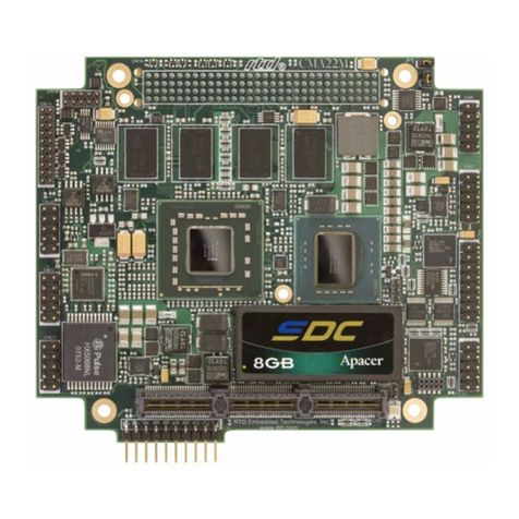
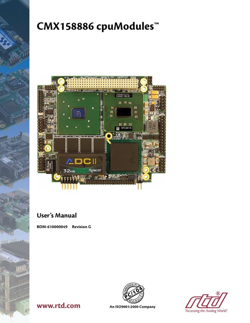
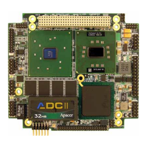
rtd CMi37786HX User manual

CMi37786HX
cpuModuleTM User’s Manual
RTD Enhanced Award BIOS Versions 6.00.xx
BDM-610000027
Rev. B
I
IS
SO
O9
90
00
01
1
a
an
nd
d
A
AS
S9
91
10
00
0
C
Ce
er
rt
ti
if
fi
ie
ed
d


Revision History
Rev A Initial Release
Rev B Changed to industrial temperature range. Updated note about booting to a floppy on
multiPort.
Published by:
RTD Embedded Technologies, Inc.
103 Innovation Blvd.
State College, PA 16803-0906
Copyright 1999, 2002-2004 by RTD Embedded Technologies, Inc.
All rights reserved
Printed in U.S.A.
The RTD Logo is a registered trademark of RTD Embedded Technologies. cpuModule and utilityModule
are trademarks of RTD Embedded Technologies. PS/2, PC/XT, PC/AT and IBM are trademarks of Interna-
tional Business Machines Inc. MS-DOS, Windows, Windows 95, Windows 98 and Windows NT are trade-
marks of Microsoft Corp. PC/104 is a registered trademark of PC/104 Consortium. All other trademarks
appearing in this document are the property of their respective owners.

Chapter 1: Introduction . . . . . . . . . . . . . . . . . . . . . . . . . . . . . . . . . . 3
The CMi37786HX cpuModule .........................................................4
Specifications ....................................................................................6
Chapter 2: Getting Started . . . . . . . . . . . . . . . . . . . . . . . . . . . . . . . . 9
Basic Connector Locations ...............................................................10
Fail safe boot ROM ...........................................................................11
Cable Kits .........................................................................................12
Connecting Power .............................................................................13
Connecting the utility cable ..............................................................14
Connecting a Keyboard ....................................................................15
Connecting to the PC/104 Bus ..........................................................16
Connecting to the PC/104-Plus PCI Bus ..........................................17
Booting the cpuModule for the First Time .......................................19
Booting to Boot Block Flash with Fail Safe Boot ROM ..................20
If You Misconfigure the cpuModule ................................................21
For More Information .......................................................................22
Chapter 3: Connecting the cpuModule . . . . . . . . . . . . . . . . . . . . . . 23
Connector Locations .........................................................................24
Auxiliary Power CN3 .......................................................................26
Serial Ports, CN7 and CN8 ...............................................................28
multiPort, CN6 - Parallel Port Mode ................................................31
multiPort, CN6 - aDIO Mode ...........................................................32
multiPort, CN6 - Floppy Controller Mode .......................................33
Multifunction Connector, CN5 .........................................................34
VGA Video Connector, CN18 ..........................................................36
Flat Panel Video Connector, CN19 ..................................................37
EIDE Connector, CN9 ......................................................................38
Bus Mouse Connector, CN4 .............................................................40
USB Connector,CN17 ......................................................................41
PC/104 Bus, CN1 and CN2 ..............................................................42
PC/104-Plus PCI Bus, CN16 ............................................................46
Chapter 4: Configuring the cpuModule (BIOS Setup) . . . . . . . . . 49
Disabling Fail Safe Boot ROM .........................................................50
Installing SSD Memory ....................................................................51
Configuring with the RTD Enhanced Award BIOS .........................52
Chapter 5: Using the cpuModule . . . . . . . . . . . . . . . . . . . . . . . . . . . 65
Memory Map ....................................................................................66
Input/Output Address Map ...............................................................67
Hardware Interrupts ..........................................................................69
The RTD Enhanced Award BIOS ....................................................71
Direct Hardware Control ..................................................................72
Advanced Digital I/O Ports (aDIO) ..................................................73
Basic Interrupt Information for Programmers: .................................79
Watchdog Timer Control ..................................................................82
Multi-Color LED ..............................................................................85
Real Time Clock Control ..................................................................86
Parallel Port Control .........................................................................87
Storing Applications On-board .........................................................88
Ways to Use the Solid State Disk Sockets ........................................89
Using BIOS Extension Devices ........................................................90
Using Conventional Solid State Devices ..........................................91
Chapter 6: Hardware Reference . . . . . . . . . . . . . . . . . . . . . . . . . . . 95
Jumpers and Solder Jumper Settings ................................................96
Mechanical Dimensions ....................................................................100
Processor Thermal Management ......................................................101
Chapter 7: Troubleshooting . . . . . . . . . . . . . . . . . . . . . . . . . . . . . . . 103
Common Problems and Solutions .....................................................104
Troubleshooting a PC/104 System ...................................................107
How to Obtain Technical Support ....................................................108
How to Return a Product ..................................................................109
Chapter 8: Limited Warranty . . . . . . . . . . . . . . . . . . . . . . . . . . . . . 111

Table Of Figures
CMi37786HX Block Diagram ..........................................................5
CMi37786HX Basic Connector Locations .......................................10
CMi37786HX Connector Locations .................................................24
CMi37786HX Jumper Locations - Top ............................................97
CMi37786HX Jumper Locations - Bottom ......................................98


Table Of Tables
SSD Conventional Devices ...............................................................7
SSD BIOS Extension Devices ..........................................................7
Power Consumption ..........................................................................8
CMi37786HX Connectors ................................................................25
Auxiliary Power Connector CN3 ......................................................26
Serial Port Base Address and IRQ Options ......................................28
Serial Port in RS-232 Mode ..............................................................28
RS-422 Serial Port Connections .......................................................29
RS-485 Serial Port Connections .......................................................29
Serial Port in RS-232 Mode ..............................................................30
multiPort Parallel Port Connector Pinout CN6 .................................31
multiPort Advanced Digital I/O Connector Pinout CN6 ..................32
multiPort Connector Floppy Pinout CN6 .........................................33
Multifunction Connector CN5 ..........................................................34
Keyboard Connector Pins on CN5 ....................................................35
VGA Video Connector CN18 ...........................................................36
Supported Video Resolutions and BIOS Settings .............................36
Flat Panel Video Connector CN12 ...................................................37
EIDE Connector CN9 .......................................................................38
Bus Mouse Connector CN4 ..............................................................40
USB Connector CN17 ......................................................................41
PC/104 XT Bus Connector, CN1 ......................................................42
PC/104 AT Bus Connector, CN2 ......................................................43
PC/104 Bus Signals ..........................................................................43
PC/104-Plus Bus Signal Assignments ..............................................46
SSD Devices .....................................................................................51
BIOS Setup Utility Keys ...................................................................52
BIOS Setup Main Menu Setup Fields ...............................................52
Standard CMOS Setup Fields ...........................................................53
Advanced BIOS Features Setup Fields .............................................54
Advanced Chipset Features Setup Fields ..........................................57
Integrated Peripherals Setup Fields ..................................................58
Power Management Setup Fields .....................................................62
PNP/PCI Configuration Setup Fields ...............................................64
First Megabyte Memory Map ...........................................................66
I/O Addresses Reserved for the cpuModule .....................................67
Hardware Interrupts Used on the cpuModule ...................................69
LED Colors .......................................................................................85
Manual LED Colors ..........................................................................85
Real Time Clock Registers ...............................................................86
Jumpers and Default Settings ...........................................................99
Solder Jumpers and Default Settings ................................................99


CMi37786HX RTD Embedded Technologies, Inc.
3
CHAPTER 1: INTRODUCTION
This manual is meant for users developing with the CMi37786HX cpu-
Module. It contains information on hardware and software of the cpu-
Module.
READ THE SPECIFICATIONS FIRST.
The manual is organized as follows:
Chapter 1: Introduction
Introduces main features and specifications.
Chapter 2: Getting Started
Provides abbreviated instructions to get started.
Chapter 3: Connecting the cpuModule
Provides information on connecting the cpuModule to peripherals.
Chapter 4: Configuring the cpuModule
Provides information on configuring hardware and software.
Chapter 5: Using the cpuModule
Provides information needed to develop applications for the cpuModule.
The chapter includes general information on the cpuModule, plus de-
tailed information on storing applications and system functions, and us-
ing utility programs.
Chapter 6: Hardware Reference
Lists jumpers and their locations and mechanical dimensions.
Chapter 7: Troubleshooting
Offers advice on debugging problems with your system.
Chapter 8: Warranty

CMi37786HX RTD Embedded Technologies, Inc.
4
The CMi37786HX cpuModule
The PC/104 cpuModules described in this manual are designed for industrial applications which re-
quire:
• software and hardware compatibility with the PC/AT world
• high-speed “number-crunching” operation
• low power consumption
• small physical dimensions
• high reliability
• good noise immunity
This cpuModule is highly integrated, combining all major functions of a PC/AT computer on one
compact board. It integrates all primary I/O functions of a AT compatible computer:
• SVGA controller
• Analog SVGA and Digital TFT outputs
• UltraDMA 33/66/100 EIDE Controller
• a keyboard interface
• parallel port
• two versatile RS232/422/485 serial ports
• a Real Time Clock
• a speaker port
• a PS/2 mouse port
• two USB ports
It also enhances standard AT-compatible computer systems by adding:
• Solid State Disk socket
• Non-volatile configuration without a battery
• Watchdog Timer
• Fail Safe Boot ROM
• A multiPort that can be configured as an ECP/EPP Parallel Port, 18 bit digital I/O, or Flop-
py Drive port

CMi37786HX RTD Embedded Technologies, Inc.
5
A simplified block diagram of the cpuModule is shown in Figure 1.
Figure 1: CMi37786HX Block Diagram
You can easily customize the cpuModule by stacking PC/104 modules such as video controllers,
modems, LANcontrollers, oranaloganddigitaldataacquisitionmodules.StackingPC/104modules
on the cpuModule avoids expensive installations of backplanes and card cages and preserves the
module's compactness.
RTD Enhanced Award BIOS is also implemented in the cpuModule. This BIOS supports ROM-
DOS™, MS-DOS, Linux, and Windows operating systems. Drivers in the BIOS allow booting from
floppy disk, hard disk, Solid State Disk, boot block flash, or DiskOnChip®, thus enabling the system
to be used with traditional disk drives or non-mechanical drives.
The cpuModule and BIOS are also compatible with most real-time operating systems for PC com-
patible computers, although these may require creation of custom drivers to use the SSD and watch-
dog timer.
VIA Eden ESP
400/733/1000MHz VT8606 Twister T
North Bridge
VT82C686B
South Bridge
SDRAM
100/133 MHz
SVGA/
FlatPanel
2xUSB1.1
RTD aDIO/
Watchdog
2 x R
S
-2
3
2
/
422
/
4
85
P
a
r
a
ll
e
l P
o
r
t
EIDE
Floppy Drive
Keyboard/Mouse
RTD Enhanced BIOS/
Failsafe Boot ROM
PCI Bus 32-bit. 33 MHz
ISA Bus

CMi37786HX RTD Embedded Technologies, Inc.
6
Specifications
CMi37786HX
• VIA Eden CPU with Twister-T Chipset
• 400 MHz to 1 GHz clock speed
• 1.05 V processor supply (provided on-board)
• 128 kB L1 Cache
• 64 kB L2 Cache
• Math coprocessor
Video Controller
• AGP S3 Savage SVGA Controller
• Analog SVGA Output
• 18 bit Digital TFT Output
• 2 / 4 / 8 / 16 / 32 MB Frame Buffer
DMA, Interrupts, Timers
• Six (6) DMA channels (8237 compatible)
• Fifteen (15) interrupt channels (8259 compatible)
• Three (3) counter/timers (8254 compatible)
USB ports • 2 USB 1.1 ports
• Boot to USB devices
• Floppy
• Hard Drive
•CD-ROM
•FlashKey
•ZIPDrive
Advanced Digital I/O (aDIO)
• Two 8 bit, TTL compatible, programmable Digital I/O Ports plus two Strobe inputs.
• One port is bit direction programmable and the other is byte direction programmable.
• Advanced Interrupt modes
• Interrupt on change
• Interrupt on match
• Interrupt on strobe
Watchdog Timer
• Selectable reset time-out of 2sec, 1sec, 0.75 sec., 0.50 sec.
• Can generate an interrupt after 1sec, 0.75 sec., 0.50 sec., 0.25 sec.
• Watchdog Refresh and Active registers are accessible from Window
Memory Configurations
• 128MB
• 256MB
Fail-safe Boot ROM
• Surface mount Flash chip that holds ROM-DOS™
• Provides an operating system with nothing else attached

CMi37786HX RTD Embedded Technologies, Inc.
7
Solid State Disk Socket
• SSD socket can hold one of the following Conventional SSD devices or BIOS Extension
Devices.
(*) Larger devices may be available in the future.
Peripherals• Two serial ports software configurable for RS232/422/485
• Baud rates from 50 to 115200 baud.
• Parallel port with SPP, ECP, EPP capability and selectable interrupts and DMA channel
• PC/AT standard keyboard port
• A PS/2 mouse port
• PC speaker port
• Real Time Clock (requires user-supplied external battery for date and time backup)
BIOS • RTD Enhanced Award BIOS
• Directly supports Solid State Disk (SSD) and M-Systems’ DiskOnChip®
• User-configurable using built-in Setup program
• Nonvolatile configuration without a battery
• Can boot from floppy disk, hard disk, Solid State Disk, fail-safe boot ROM, or USB.
Connections
• AT bus, per PC/104 specifications (64-pin CN1, 40-pin CN2)
• PCI bus, per PC/104-Plus specifications (120-pin CN16)
• Auxiliary Power Connector (12-pin CN3)
• PS/2 Mouse Connector (4-pin CN4)
• Multifunction connector (10-pin CN5)
• multiPort connector (26-pin CN6)
• Serial port 1 connector (10-pin CN7)
• Serial port 2 connector (10-pin CN8)
• SVGA Monitor connector (10-pin CN18)
• TFT Monitor connector (30-pin CN19)
• Dual USB port connector(10-pin CN17)
Table 1: SSD Conventional Devices
Device Full Read/Write
Access 128Kbytes 256Kbytes 512Kbytes 1Mbyte
Atmel 5V Flash yes yes yes yes no
SRAM yes yes no yes no
NOVRAM yes yes no yes no
EPROM Read Only yes yes yes yes
AMD 5V Flash Read Only yes no yes no
Table 2: SSD BIOS Extension Devices
Device Full Read/Write
Access Maximum Number per
cpuModule Sizes
DiskOnChip®
2000 yes 1 16MB -
1GB *

CMi37786HX RTD Embedded Technologies, Inc.
8
• EIDE Hard Drive Connector (44-pin CN9)
• CMOS Battery Connector (2-pin JP8)
• Fan Power Connectors (2-pin JP3 and JP7)
Physical Characteristics
• Dimensions: 3.550 x 3.850 x 0.6 inches (90.2 x 95.9 x 16mm)
• Weight (mass): 4.5 ounces (130 grams)
• PCB: 14-layer, mixed surface-mount and through-hole
Operating environment
• Power supply: 5V +/- 5%, 20 Watts
• Operating temperature: -40 to +85 degrees C case (with proper cooling) See Processor
Thermal Management on page 101.
• Storage temperature:-55 to +125 degrees C.
• Operating relative humidity: 0 to 95%, non-condensing
Power Consumption
Exact power consumption depends on the peripherals connected to the board, the selected SSD con-
figuration and the memory configuration.
The table below lists power consumption for typical configurations and clock speeds:
Table 3: Power Consumption
Module Speed RAM SSD Consumption,
Typical Consumption
Maximum
CMi37786HX 400 MHz 128 or 256 MB None 7.6 W 10.0 W
CMi37786HX 733 MHz 128 or 256 MB None 9.7 W 14.5 W
CMi37786HX 1 GHz 128 or 256 MB None 11.5 W 17.0W

CMi37786HX RTD Embedded Technologies, Inc.
9
CHAPTER 2: GETTING STARTED
For many users, the factory configuration of the cpuModule can be used
to get a PC/104 system operational. If you are one of these users, you can
get your system up and running quickly by following a few simple steps
described in this chapter. Briefly, these steps are:
• Connect power.
• Connect the utility cable.
• Connect a keyboard.
• Default BIOS Configuration
• Fail Safe Boot ROM
• Connect a VGA monitor to the SVGA connector.
Refer to the remainder of this chapter for details on each of these steps.

CMi37786HX RTD Embedded Technologies, Inc.
10
Basic Connector Locations
The following figure and table show the connectors used in this chapter
Figure 2: CMi37786HX Basic Connector Locations
For a complete listing of connectors, please refer to Connector Locations on page 24.
NOTE! Pin 1 of each connector is indicated by a square solder pad
on the bottom of the PC board and a white square silk-
screened on the top of the board.

CMi37786HX RTD Embedded Technologies, Inc.
11
Fail safe boot ROM
Fail Safe Boot ROM is supplied with the board. This feature is programmed into a surface mount
flash chip. The programmed boot ROM is ROM-DOS™. Fail Safe Boot ROM allows the system
to boot without any attached storage devices. i.e. floppy, IDE, SSD. Installing jumper JP5 will force
the cpuModule to use fail safe boot ROM, as well as load the default BIOS settings. This configu-
ration allows you to boot to non-volatile onboard ROM-DOS™.

CMi37786HX RTD Embedded Technologies, Inc.
12
Cable Kits
For maximum flexibility, cables are not provided with the cpuModule. You may wish to purchase
our cable kit for the cpuModule.
The XK-CM42 cable kit contains the following:
• Utility Board Cable (keyboard, mouse, battery, reset, speaker, SVGA, COM ports, Multi-
Function Port)
• IDE Cable (for 3.5" Hard Drive)
• IDE Cable (for 2.5" Hard Drive)
• Power cable (DIL12 to wire leads)
• Dual USB cable
Table of contents
Other rtd Computer Hardware manuals

rtd
rtd cpuModule CME37786HX User manual

rtd
rtd CMX58886CX User manual

rtd
rtd CNV36JXNX User manual

rtd
rtd BDM-610000049 User manual

rtd
rtd cpuModule CML47786HX User manual

rtd
rtd CMX34KB User manual

rtd
rtd CMV6586DX133 User manual

rtd
rtd cpuModule CMX147786HX User manual

rtd
rtd LAN24710 User manual

rtd
rtd DM6210 User manual
Popular Computer Hardware manuals by other brands

Moxa Technologies
Moxa Technologies ABC-02-USB Quick installation guide

Supermicro
Supermicro SC721TQ-250B user manual

StarTech.com
StarTech.com ISA1S550 instruction manual

Microchip Technology
Microchip Technology OLED1 Xplained Pro user guide

AirLive
AirLive WN-200USB user manual

Ublox
Ublox EVK-JODY-W163 quick start