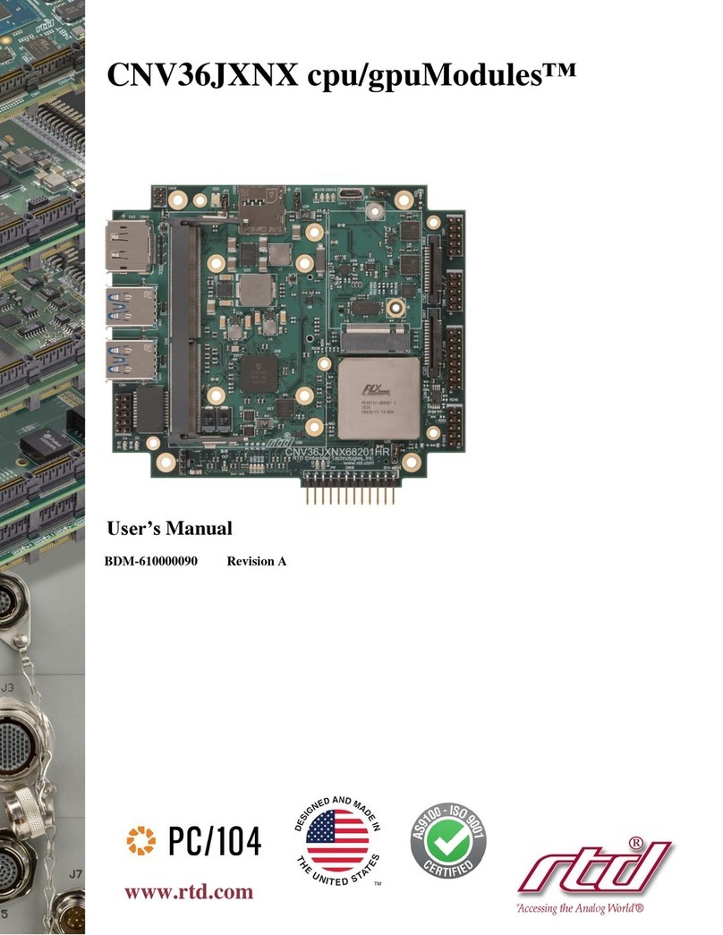
rtd CMX34KB User manual


CMX34KB cpuModules™ User’s Manual
RTD Document Number: BDM-610000090 Revision A
Copyright © 2009-2021 RTD Embedded Technologies, Inc. All rights reserved.
Trademarks
AdvancedAnalog I/O, Advanced Digital I/O, aAIO, aDIO, a2DIO, Autonomous SmartCal, “Catch the Express”,
cpuModule, dspFramework, dspModule, expressMate, ExpressPlatform, HiDANplus, “MIL Value for COTS
prices”, multiPort, PlatformBus, and PC/104EZ are trademarks, and “Accessing theAnalog World”, dataModule,
IDAN,HiDAN, RTD, and the RTD logo are registered trademarks ofRTD Embedded Technologies, Inc (formerly
RealTime Devices, Inc.). PS/2 is a trademark of International Business Machines Inc. PCI, PCI Express, and PCIe
are trademarks of PCI-SIG. PC/104, PC/104-Plus, PCI-104, PCIe/104, PCI/104-Express and 104 are trademarks
of the PC/104 Embedded Consortium. All other trademarks appearing in this document are the property of their
respective owners.
Failure to follow the instructions found in this manual may result in damage to the product described in this
manual, or other components of the system. The procedure set forth in this manual shall only be performed by
persons qualified to service electronic equipment. Contents and specifications within this manual are given
without warranty, and are subject to change without notice. RTD Embedded Technologies, Inc. shall not be liable
for errors or omissions in this manual, or for any loss, damage, or injury in connection with the use of this manual.

iv
CMX34KB cpuModules™
®

BDM-610000090 Rev A CMX34KB User’s Manual 6
Table of Contents
Chapter 1 Introduction.....................................................................11
CMX34KB cpuModules...............................................................................................................12
aDIO.................................................................................................................................................13
Ordering Information..................................................................................................................14
CMX34KB Model Options............................................................................................................14
Cable Kits and Accessories............................................................................................................14
Board Features..............................................................................................................................15
I/O....................................................................................................................................................16
RTD Enhanced BIOS .....................................................................................................................18
Block Diagram...............................................................................................................................19
Specifications..................................................................................................................................20
Physical Characteristics .................................................................................................................20
Power Consumption........................................................................................................................20
Operating Conditions .....................................................................................................................21
Electrical Characteristics ...............................................................................................................22
Migrating to RTD’s Intel® Xeon Series cpuModules...........................................................24
Connector Pinout & Function Differences ...................................................................................24
Software Differences......................................................................................................................25
Contact Information ....................................................................................................................26
Chapter 2 Getting Started ...............................................................27
Connector Locations....................................................................................................................28
Selecting the Stack Order for the CMX34KB .........................................................................29
Stack Example...............................................................................................................................30
Connecting to the Stack...............................................................................................................31
Power Input Connections............................................................................................................31
Connecting to the Utility Port 2.0 Connector..........................................................................32
Booting the CMX34KB cpuModule for the First Time.........................................................32
Chapter 3 Connecting the cpuModule .........................................33
Proper Grounding Techniques ...................................................................................................34
Connector Locations....................................................................................................................34

BDM-610000090 Rev A CMX34KB User’s Manual 7
Auxiliary Power (CN3)................................................................................................................36
Utility Port 2.0 Connector (CN5)...............................................................................................38
USB 2.0 Connector.........................................................................................................................39
Speaker.............................................................................................................................................39
System Reset...................................................................................................................................39
Soft Power Button ..........................................................................................................................39
Battery..............................................................................................................................................39
DisplayPort Connector (CN4)....................................................................................................40
Serial Port 1 (CN7) and Serial Port 2 (CN8)...........................................................................42
Serial Port UART............................................................................................................................42
RS-232 Serial Port (Default) .........................................................................................................42
RS-422 or RS-485 Serial Port........................................................................................................43
Dual Serial Port Modes..................................................................................................................46
Advanced Digital I/O (aDIO™) Port (CN6)............................................................................48
Ethernet (10/100/1000Base-T and -TX) Connector (CN20, CN30) .....................................49
PCIe/104 Type 2 Bus (CN1 - Top and CN2 - Bottom)............................................................50
PCIe/104 Type 2 Compatibility.....................................................................................................54
PCIe Link Configuration................................................................................................................54
Optional RTC Battery Input (CN13)........................................................................................55
SATA 3.0 (CN15)..........................................................................................................................55
USB 2.0 Connector (CN27) ...........................................................................................................55
USB 3.0 Connector (CN11) ...........................................................................................................56
Fan Connector (CN12) ..................................................................................................................56
Chapter 4 Using the cpuModule ....................................................57
The RTD Enhanced BIOS.............................................................................................................58
Configuring the RTD Enhanced BIOS..........................................................................................58
Entering the BIOS Setup through the Graphical BIOS Menu.....................................................58
Field Selection ................................................................................................................................60
Main Menu Setup Fields ................................................................................................................60
Operating System Specific Usage ..............................................................................................61
Windows®.......................................................................................................................................61
Linux®.............................................................................................................................................61
UEFI OS Installations ....................................................................................................................61
Non-Standard Serial Port Modes ..............................................................................................62

BDM-610000090 Rev A CMX34KB User’s Manual 8
Advanced Digital I/O Ports (aDIO™).......................................................................................63
Digital I/O Register Set..................................................................................................................63
Interrupts..........................................................................................................................................65
SATA Controller Configuration.................................................................................................67
SATA Port Mappings, by Connector.............................................................................................67
Onboard SATA Storage ..................................................................................................................67
SATA Links on the PCIe/104 Type Connectors ...........................................................................67
Watchdog Timer Control.............................................................................................................68
Register Description........................................................................................................................68
Thermal Management..................................................................................................................69
Thermal Warning............................................................................................................................69
ACPI-Enforced Thermal Protection..............................................................................................69
Power Management......................................................................................................................70
Advanced Configuration and Power Interface (ACPI)................................................................70
Power Button Modes......................................................................................................................70
Low-Power Wake Options .............................................................................................................70
AT vs. ATX Power Supplies...........................................................................................................71
ATX Power Supply Signals............................................................................................................71
Reducing Power Consumption ......................................................................................................71
Multi-Color LED ..........................................................................................................................72
Reset and Event Status Register................................................................................................73
Trusted Platform Module............................................................................................................75
Features and Settings That Can Affect Boot Time.................................................................76
Boot Device Order..........................................................................................................................76
Add-On Cards With BIOS Extensions..........................................................................................76
VGA Controller...............................................................................................................................76
Hard Drive Type..............................................................................................................................76
Monitor Type...................................................................................................................................76
System Recovery...........................................................................................................................77
Reset Button Recovery...................................................................................................................77
Load Default BIOS Settings ..........................................................................................................77
Serial Power-On-Self-Test (POST) Code Output.........................................................................77
Appendix A Hardware Reference..................................................78
Jumper Settings and Locations..................................................................................................79
BDM-610000090 Rev A CMX34KB User’s Manual 9
Onboard PCI/PCIe Devices........................................................................................................80
Physical Dimensions.....................................................................................................................81
Heatsink Dimensions....................................................................................................................82
Flat-Heatspreader Dimensions...................................................................................................83
Appendix B Troubleshooting...........................................................84
Common Problems and Solutions..............................................................................................85
Troubleshooting a PC/104 System.............................................................................................86
How to Obtain Technical Support.............................................................................................87
Appendix C IDAN™ Dimensions and Pinout ............................88
IDAN Contents..............................................................................................................................89
IDAN Dimensions.........................................................................................................................90
IDAN Connector Locations.........................................................................................................91
External I/O Connections ...........................................................................................................93
Appendix D Additional Information ............................................97
Application Notes .........................................................................................................................97
Drivers and Example Programs.................................................................................................97
Interrupt Programming ..............................................................................................................97
Serial Port Programming............................................................................................................97
PC/104 Specifications...................................................................................................................97
Appendix E Limited Warranty.......................................................98
Appendix E Limited Warranty

BDM-610000090 Rev A CMX34KB User’s Manual 10

BDM-610000090 Rev A CMX34KB User’s Manual 11
Chapter 1 Introduction
This manual provides comprehensive hardware and software information for users developing with the
CMX34KB PCIe/104 cpuModule.
Note Read the specifications beginning on page 20 prior to designing with the cpuModule.
This manual is organized as follows:
Chapter 1 Introduction
introduces main features and specifications
Chapter 2 Getting Started
provides abbreviated instructions to get started quickly
Chapter 3 Connecting the cpuModule
provides information on connecting the cpuModule to peripherals
Chapter 4 Using the cpuModule
provides information to develop applications for the cpuModule, including general
cpuModule information, detailed information on storing both applications and system
functions, and using utility programs
Appendix A Hardware Reference
lists jumper locations and settings, physical dimensions, and processor thermal
management
Appendix B Troubleshooting
offers advice on debugging problems with your system
Appendix C IDAN™ Dimensions and Pinout
provides connector pinouts for the cpuModule installed in an RTD Intelligent Data
Acquisition Node (IDAN) frame
Appendix D Additional Information
lists sources and websites to support the cpuModule installation and configuration
Appendix E Limited Warranty

BDM-610000090 Rev A CMX34KB User’s Manual 12
CMX34KB cpuModules
RTD'sCMX34KBcpuModulerepresentsthe latestin high performance PCIe/104embedded controllers with
a Type 2 bus. Thisdesign isbasedon an Intel® Kaby Lake Xeon processor with CM238 Platform Controller
Hub. The CMX34KBis offered with either a 2.2Ghz Quad-Core processor ora 3GHz Quad-Coreprocessor.
Gen 3.0 PCIe support consists of 8 PCIe x1 lanes and 4 PCIe x4 lanes. The top PCIe bus connector contains
4 x1 lanes and 2 x4 lanes. The bottom connector also contains 4 x1 lanes and 2 x4 lanes.
Onboard memory consists of 16 GB of embedded ECC DDR4 DRAM with a speed of 2400 MT/s (1200
MHz).
The cpuModule’s DisplayPort video interface supports audio and a maximum resolution of 4096 x 2304.
A Serial-ATA (SATA) controller provides six SATA 3.0 links. Two links to the top and two links to the
bottom PCIe connectors. One of the remaining two links is routed to an embedded 60 GB drive and the last
link is routed to an onboard SATA connector.
A xHCI controller supplies a USB 3.0 connection, with up to 625 MB/sec data throughput, to a USB A
connector. The controller also supplies 5 USB 2.0 connections. Four connections are routed to 10 pin
connectors and the last one is utilized in the Utility port for the use of a keyboard and mouse.
Network connectivity is provided by two 10/100/1000 Mbps Intel®i210 Ethernet controllers.
Other features include RS-232/422/485 COM ports and Advanced Digital I/O (aDIO).
RTD has implemented additional features for increased utility and security. These includeRS-232/422/485
COM ports, Advanced Digital I/O (aDIO), an Advanced Watchdog Timer and a Trusted Platform Module
(TPM 2.0). The CMX34KB is also madeavailable in a rugged and fan-less IDAN enclosure.
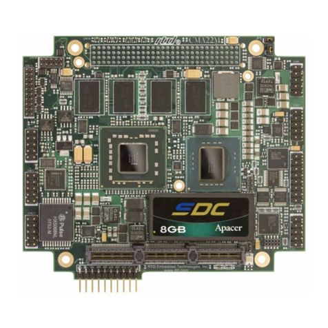
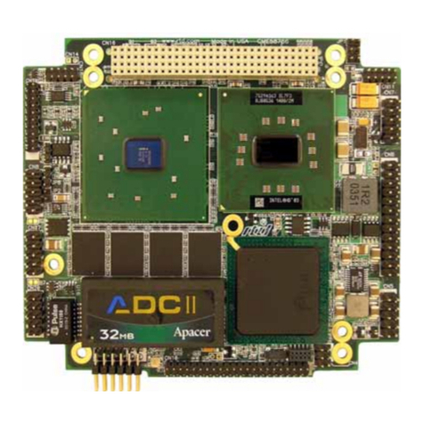
Figure 1 CMX34KB cpuModule (top view)

BDM-610000090 Rev A CMX34KB User’s Manual 13
You can easily customize the cpuModule by stacking PCI/104-Express or PCIe/104 modules such as video
controllers, Digital Signal Processors, drive carriers, LAN controllers, or analog and digital data acquisition
modules. Stacking modules onto the cpuModule avoids expensive installations of backplanes and card
cages and preserves the module's compactness.
The cpuModule uses the RTD Enhanced BIOS. Functionality in the BIOS allows booting from hard disk,
UEFIshell, USB, or network booting.
The cpuModule and BIOS are compatible with any real-time operating systems for PC compatible
computers, although these may require creation of custom drivers to use the aDIO and watchdog timer.
aDIO
RTD’s exclusive aDIO™ is 12 digital bits configured as 8 bit-direction programmable and 4-bit
port-direction programmable I/O, plus 2 strobe inputs giving you any combination of inputs and outputs.
Match, event, and strobe interrupt modes mean no more wasting valuable processor time polling digital
inputs. Interrupts are generated when the 8 bit-direction programmable digital inputs match a pattern or on
any value change event. Bit masking allows selecting any subgroup of eight bits. The strobe input latches
data into the bit-programmable port and generates an interrupt.

BDM-610000090 Rev A CMX34KB User’s Manual 14
Ordering Information
The CMX34KB cpuModule is available with a selection of processors and heatsinks. The cpuModule can
also be purchased as part of an Intelligent Data Acquisition Node (IDAN™) building block, which consists
ofthe cpuModule and a milled aluminum IDAN frame. The IDAN building block can be used in just about
any combination with other IDAN building blocks to create a simple but rugged PC/104 stack. Refer to
Appendix C, IDAN™ Dimensions and Pinout, for more information. The CMX34KB cpuModule can also
be purchased as part of a custom-built RTD HiDAN™ or HiDANplus High Reliability Intelligent Data
Acquisition Node. Contact RTD for more information on its high reliability PC/104 systems.
CMX34KB Model Options
The basic cpuModule model options are shown below. Refer to the RTD website (www.rtd.com) for more
detailed ordering information and any new variations that may be available.
Table 1CMX34KB cpuModule Model Options1
CMX34KBQ2200HR-16384/S60GX Intel®Xeon® E3-1505L, Quad Core 2.2 GHz 16GB
DDR4-SDRAM
CMX34KBQ3000HR-16834/S60GX Intel®Xeon® E3-1505M, Quad Core 3.0 GHz 16GB
DDR4-SDRAM
CMX34KBD2100HR-16384/S60GX Intel®i3-7102E, Dual Core 2.1 GHz 16GB
DDR4-SDRAM
22mm
22mm
22mm
CMX34KBD2200HR-16384/S60GXF CMX34KBD2200HR-16384/S60GX with Flat Heatspreader 22mm
CMX34KBQ3000HR-16384/S60GXF CMX34KBQ3000HR-16384/S60GX with Flat Heatspreader 22mm
CMX34KBQ3000HR-16384/S60GXF CMX34KBD2100HR-16384/S60GX with Flat Heatspreader 22mm
1. All ordering options include a Trusted Platform Module (TPM 2.0).
Cable Kits and Accessories
For maximum flexibility, RTD does not provide cables with the cpuModule. You may wish to purchase the
CMX34KB cpuModule cable kit (XK-CM113), which contains:
•Utility Port 2.0 multi-function cable (2x USB 2.0 ports, battery, reset button, power button,
speaker)
•Two serial port cables (DIL-10 to DSUB-9)
•VGAmonitor cable (DIL-10 to high density 15-pin DSUB)
•aDIO cable (DIL-16 to DSUB-25)
•Two USB cables (5-pin SIL to USB A)
•PCIe/104 Type 2 break-out board (provides standard PC interfaces for SATA and USB devices)
•Two ethernet cables (DIL-10 to RJ-45)
For additional accessories, refer to the RTD website.
Part Number
Description
Stack
Height

BDM-610000089 Rev A CMX34KB User’s Manual 15
Board Features
•Intel®Xeon® E3-1505 Series Processor:
Part Number
Cores
Core
Frequency
L1 Cache
L2 Cache
L3 Cache
Stack Height
CMX34KBQ2100
Two
2.1 GHz
128 KByte
1 MByte
8 MByte
22mm
CMX34KBQ2200
Four
2.2 GHz
128 KByte
1 MByte
8 MByte
22mm
CMX34KBQ3000
Four
3.0 GHz
128 KByte
1 MByte
8 MByte
22mm
1. Discreet L1 and L2 cache structures for each core.
–Intel®Xeon® technology
•i3-7102E Duo Core Processor
•E3-1505L Quad Core Processor
•E3-1505M Quad Core Processor
–Thermal Throttling reduces clock speed to prevent thermal runaway
–14 nm process
–Max Core Temperature of 100 C
•16 GBytes BGA DDR4 SDRAM with ECC
–Dual-channel memory interface
–Transfer rates up to 2400 MT/s Data Rate
–Surface Mounted for maximum reliability
•Stackable 156-pin PCIe/104 Type 2 bus on top
–Two PCI Express x4 Links. Gen 3, 8 GT/s
–Four PCI Express x1 Links. Gen 3, 8 GT/s
–Two SATA 3.0, Rev 3.0 600MB/s
–ATX Power Supply Signaling
–RTC Battery
•Stackable 156-pin PCIe/104 Type 2 bus on bottom
–Two PCI Express x4 Links. Gen 3, 8 GT/s
–Four PCI Express x1 Links. Gen 3, 8 GT/s
–Two SATA 3.0, Rev 3.0 600MB/s
–Two USB 2.0
–ATX Power Supply Signaling
–RTC Battery
•Advanced Thermal Management
–Thermal Monitor throttles processor and memory to prevent thermal runaway
–Modified heatsinks and flat heat spreaders are available
–Mini Fan Heatsink with Auto Fan control
–Passive Structural Heatsink & Heatpipes in IDAN and HiDAN System Configurations
•Advanced Configuration and Power Interface (ACPI)
–Wake events include:
•USB event (device insertion, keyboard keystroke, etc.)
•Power Switch

BDM-610000089 Rev A CMX34KB User’s Manual 16
•Real-Time Clock (external battery required to maintain time only)
•Nonvolatile storage of CMOS settings without battery
•Advanced Watchdog timer
•Complete PC-compatible Single Board Computer
•Trusted Platform Module (TPM)
–Fully compliant to the Trusted Computing Group (TCG) Trusted Platform Module (TPM)
version 2.0 specification
–Provides for secure storage of cryptographic keys
I/O
•DisplayPort Interface Rev. 1.4
–Max Resolution 4096 x 2304
–Audio over DisplayPort
•Two Gigabit Ethernet Ports
–Intel®WGI210IT PCI Express x1 Controller
–10/100/1000 Auto-negotiation
–Jumbo Frame Support (9.5 kB)
–Automatic MDI/MDI-X crossover capable
•Software-configurable RS-232/422/485 serial ports
–16550 compatible UARTs for high-speed
–120 Ohm Termination resistors for RS-422/485 through BIOS Configuration
–Fully jumperless configuration
–Increased FIFO size of 512 bytes for both transmit and receive.
–Supports echo cancellation, Auto-RTS and Auto-CTS
–Each serial port can be configured as two truncated serial ports for a total of four serial ports
•Advanced Digital I/O (aDIO)
–One 8-bit bit-programmable I/O with Advanced Digital Interrupt Modes
–One 4-bit port programmable as input or output
–Event Mode Interrupt generates an interrupt when any input bit changes
–Match Mode Interrupt generates an interrupt when input bits match a preset value
–External Strobe Mode latches 8 data inputs and generates an interrupt
–Two Strobes can be configured as readable inputs
•Three USB 2.0 (Universal Serial Bus) Ports
–Supports 480 Mb/s (high-speed), 12Mb/s (full-speed), and 1.5Mbs (low speed) peripherals
–Automatic resettable over-current protection (500 mA @ 5 Vdc per port)
–USB Boot capability
–Three ports on 0.1” I/O headers: two on CN27, and one on CN5
•One USB 3.0 (Universal Serial Bus) Port
–Supports 625 MByte/s (Super Speed)
–USB Boot capability
–On CN11, a USB A connector
•Automatic resettable over-current protection (750 mA @ 5 Vdc)
•SerialATA(SATA)
–Six SATArevision 3.0 links

BDM-610000089 Rev A CMX34KB User’s Manual 17
•Two links to the top-side PCIe connector
•Two links to the bottom-side PCIe connector
•One link to an onboard SATA connector CN15
•One link to the onboard surface-mount SATA Flash drive
–Onboard 32 GB SATA 3.0Flash drive
•Built in Wear Leveling, Error Correction and Bad Block Management
•SMART supported (Self-Monitoring, Analysis and Reporting Technology)
–Compatibility mode supports legacy operating systems.
•Utility Port 2.0 Connector
–1x USB 2.0 (Universal Serial Bus) Port with 500 mA over-current protection
–Speaker port (0.1 W output)
–Hardware Reset input
–Soft Power Button input
•Battery input for Real Time Clock
•Power Management
–ACPI - Advanced Configuration and Power interface
–ATX support for “Soft Off”
–ATX Power signals

BDM-610000090 Rev A CMX34KB User’s Manual 18
RTD Enhanced BIOS
•User-configurable using built-in Setup program
•Flash-based backup of CMOS Settings; no battery required to store CMOS settings
•Supports boot from SATA, USB, or Network
•UEFI (Unified Extensible Firmware Interface) Shell
•Special RTD Enhancements

BDM-610000090 Rev A CMX34KB User’s Manual 19
Block Diagram
The next figure shows a simplified block diagram of the CMX34KB cpuModule.
Figure 2 CMX34KB cpuModule Simplified Block Diagram

BDM-610000090 Rev A CMX34KB User’s Manual 20
Specifications
Physical Characteristics
Basic dimensions and the weight of the CMX34KB are listed below. For a more detailed dimensional
drawing, refer to the Physical Dimensions section.
•Dimensions
–Board Size (connectors not included)
•Length (L): 99.695 mm L (3.925")
•Width (W): 115.57 mm W (4.550")
–Stand-off Height Above the CPU:
•Quad-core models 22.000 mm (0.866")
–Stand-off Height Below the CPU:
•All versions: 15.240mm (0.600")
•Weight: Approximately 0.261 Kg (0.574 lbs.) with fan Heatsink
•Weight: Approximately 0.377 Kg (0.832 lbs.) with flatHeatspreader
•Weight: Approximately 0.140 Kg (0.308 lbs.) just board
•IDAN Weight: Approximately 0.765 Kg (1.686 lbs.)
Power Consumption
Exact power consumption depends on the actual application.Typical power consumption of the CMX34KB
is listed in Table 3. It is expected that power consumption of a typical application will be a combination of
these scenarios.
Table 2 Typical Power Consumption
CMX34KBD2200HR-16834 21.7 W
CMX34KBQ3000HR-16834 34.8 W
CMX34KBD2100HR-16834 16.8 W
Note Themeasurements listedabove areintended to represent common usage scenarios. The
cpuModule’s power consumption is heavily influenced by the running software and system
activity.
Part Number
Typical Power
Consumption
This manual suits for next models
3
Table of contents
Other rtd Computer Hardware manuals

rtd
rtd ECAN1000HR User manual

rtd
rtd SYNC25104HR User manual

rtd
rtd LAN24710 User manual

rtd
rtd cpuModule CME37786HX User manual

rtd
rtd cpuModule CMX47786HX User manual

rtd
rtd CAN SPIDER User manual

rtd
rtd CMV6586DX133 User manual

rtd
rtd CMX58886CX User manual

rtd
rtd DM6210 User manual

rtd
rtd FPGA35S6045HR User manual