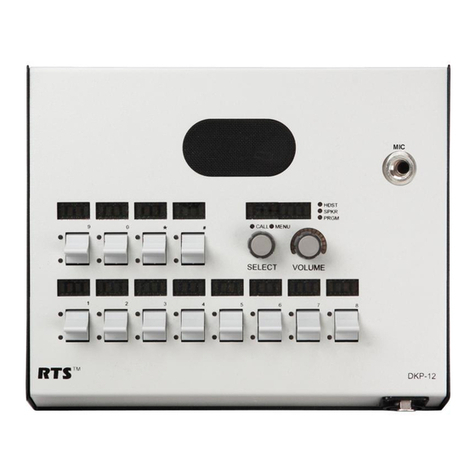
RTS MCS-325 User manual

MCE-325
User Station
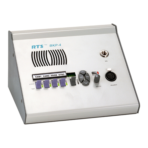
The MCE-325 is a four-channel, programmable intercom station. It may be used as a headset station or, with the addition of
the MCS-325 Modular Speaker, as a speaker station. It may be mounted in a console or equipment rack via optional mounting
kits. The MCE-325 can be used with either two-wire or four-wire intercom lines, or a combination of both. In the labeling on the
MCE-325, references to channels 1, 2, 3, and 4 indicate two-wire lines; references to four-wire A and four-wire B indicate four-
wire lines. The MCE-325 can be interfaced to a variety of external devices including external program sources, two-way radios,
paging systems, and satellite circuits.
Call Signaling
Call signaling is accomplished using an inaudible (20 kHz)
signal to activate a call indicator LED.
Remote “talk-off”
Active, unattended remote station microphones may be
deactivated by momentarily injecting an inaudible (24 kHz)
signal into the corresponding intercom line. The MCE-325
can send and receive “talk-off” signals.
VOX circuit
The MCE-325 may be programmed for voice activation of
the microphone.
Simple IFB
Program audio assigned to a channel is interrupted during
talk.
External device keying
External devices, such as two-way radios, speaker mute
relays, or paging systems may be activated through key
outputs at the auxiliary connector on the rear panel. The key
outputs may also be used to expand the simple IFB function,
allowing any one of a number of MCE-325 stations to inter-
rupt the program source and talk on the line.
Microphone Limiter
The microphone preamplier circuit contains a limiter, which
helps to equalize voice levels.
Fully programmable
Retains programming even when power is shut off.
Instantaneous Auto-Reset
Instantaneous Auto Reset (IAR), the newest technology in
performance and safety, which uses a revolutionary new
circuitry that dynamically monitors line fault conditions. Then,
when the fault is removed, automatically brings individual
power supply channels up.
Features
Line Drawing

MCE-325 Specications
General
Bridging Impedance (to line) 10,000 Ω typical
Noise Contribution to 200-Ω Line -90 dBu
Call Signal Frequency 20 kHz, crystal controlled
Talk-off Frequency 24 kHz, crystal controlled
Microphone Preamplier
Maximum Voltage Gain 54 dB
Frequency Response 100 Hz to 8,000 Hz, ±3 dB
Input Impedance 1,000 Ω
Limiter Range 30 dB
Headphone Amplier
Maximum Voltage Gain 30 dB
Frequency Response 100 Hz to 8,000 Hz, ±3 dB
Headphone Impedance 50 to 600 Ω
Output Power 150 mW into 50 Ω
Output Voltage Level 8 Vp-p
Speaker Amplier
Maximum Voltage Gain 30 dB
Frequency Response 100 Hz to 8,000 Hz, ±3 dB
Speaker Impedance 8 to 16 Ω
Output Power per Amplier 5W into 8 Ω
Output Voltage Level 16 Vp-p
Power and Mechanical
Power Requirements 115 or 230 VAC, 20 VA max version available
12 to 25 VDC, 100 to 125 mA quiescent, 900 mA max
Dimensions 1.72” (44 mm) tall, 8.2” (208 mm) wide, 8” (203 mm) deep
Weight 4.5 lbs (1.93kg)
Material/Finish Thermo-plastic front panel, aluminum case, light gray nish
Connectors
Intercom Line Connector XLR type, 3-pin (male-female loop through on two-wire
Channel 1 and 2, or four-wire channel A; Female only on two-wire channel 3 and 4, or four-wire channel B
Dynamic Mic XLR type, 6-pin female
Carbon Mic ¼-inch phone jack, 3-circuit
Auxiliary Connector 25-pin, female, D-Sub
Program Inputs ¼-inch phone jack, 3-circuit
Speaker Output ¼-inch phone jack, 3-circuit
Panel Mic ¼-inch phone jack, metal busing, 3-circuit
Ordering Information
MCE-325 A5F • 2 or 4 channel user programmable
modular user station • Catalog Number: 9000646400
MCE-325 A4F • 2 or 4 channel user programmable
modular user station with A4M headset connector, UL
approved • Catalog Number: 9000646401
This specications information is preliminary and is subject to change without notication.
Brand names mentioned are the property of their respective companies.
Contact Information
Telex Communications, Inc.
12000 Portland Avenue South
Burnsville, Minnesota 55337
Telephone: (800) 392-0498
Fax: (800) 323-0498
Form Number: 38110-342
Date: March, 2006

9350-6464-00 Rev L, 11/2006
USER INSTRUCTIONS
MODEL MCE325
PROGRAMMABLE USER STATION

PROPRIETARY NOTICE
The product information and design disclosed herein were
originated by and are the property of Telex Communications,
Inc. Telex reserves all patent, proprietary design, manufactur-
ing, reproduction, use and sales rights thereto, and to any arti-
cle disclosed therein, except to the extent rights are expressly
granted to others.
COPYRIGHT NOTICE
Copyright 2006 by Telex Communications, Inc. All rights
reserved. Reproduction, in whole or in part, without prior
written permission from Telex is prohibited.
WARRANTY NOTICE
See the enclosed warranty card for further details.
CUSTOMER SUPPORT
Technical questions should be directed to:
Customer Service Department
RTS/Telex Communications, Inc.
12000 Portland Avenue South
Burnsville, MN 55337 USA
Telephone: 800-392-3497
Fax: 800-323-0498
RETURN SHIPPING INSTRUCTIONS
Customer Service Department
Telex Communications, Inc. (Lincoln, NE)
Telephone: 402-467-5321
Fax: 402-467-3279
Factory Service: 800-553-5992
Please include a note in the box which supplies the company
name, address, phone number, a person to contact regarding
the repair, the type and quantity of equipment, a description
of the problem and the serial number(s).
SHIPPING TO THE MANUFACTURER
All shipments of product should be made via UPS Ground,
prepaid (you may request from Factory Service a different
shipment method). Any shipment upgrades will be paid by
the customer. The equipment should be shipped in the origi-
nal packing carton. If the original carton is not available, use
any suitable container that is rigid and of adequate size. If a
substitute container is used, the equipment should be
wrapped in paper and surrounded with at least four (4) inches
of excelsior or similar shock-absorbing material. All ship-
ments must be sent to the following address and must include
the Proof of Purchase for warranty repair. Upon completion
of any repair the equipment will be returned via United Par-
cel Service or specified shipper, collect.
Factory Service Department
Telex Communications, Inc.
8601 East Cornhusker Hwy.
Lincoln, NE 68507 U.S.A.
Attn: Service
This package should include the following:

i
TABLE OF CONTENTS
Description & Specifications 1-1
Description . . . . . . . . . . . . . . . . . . . . . . . . . . . . . . . . . . . . . . . . . . . . . . . . . . . . . . . . . 1-1
General . . . . . . . . . . . . . . . . . . . . . . . . . . . . . . . . . . . . . . . . . . . . . . . . . . . . . . . . . 1-1
Features . . . . . . . . . . . . . . . . . . . . . . . . . . . . . . . . . . . . . . . . . . . . . . . . . . . . . . . . . 1-1
Front Panel Features . . . . . . . . . . . . . . . . . . . . . . . . . . . . . . . . . . . . . . . . . . . . . . . . . . 1-2
Channel Selector and Operation Buttons . . . . . . . . . . . . . . . . . . . . . . . . . . . . . . . . . . . . . . 1-2
Volume Controls . . . . . . . . . . . . . . . . . . . . . . . . . . . . . . . . . . . . . . . . . . . . . . . . . . . 1-2
Sidetone Nulling Trimmers . . . . . . . . . . . . . . . . . . . . . . . . . . . . . . . . . . . . . . . . . . . . . . 1-2
Connections, Inputs and Outputs . . . . . . . . . . . . . . . . . . . . . . . . . . . . . . . . . . . . . . . . . . . . 1-2
Front Panel . . . . . . . . . . . . . . . . . . . . . . . . . . . . . . . . . . . . . . . . . . . . . . . . . . . . . . 1-2
Panel Microphone Jack . . . . . . . . . . . . . . . . . . . . . . . . . . . . . . . . . . . . . . . . . . . . . . . . . . . . . . 1-2
Rear Panel Features. . . . . . . . . . . . . . . . . . . . . . . . . . . . . . . . . . . . . . . . . . . . . . . . . . . 1-3
Intercom Lines . . . . . . . . . . . . . . . . . . . . . . . . . . . . . . . . . . . . . . . . . . . . . . . . . . . . . . . . . . . 1-3
External Program Input . . . . . . . . . . . . . . . . . . . . . . . . . . . . . . . . . . . . . . . . . . . . . . . . . . . . . . 1-3
Speaker Output . . . . . . . . . . . . . . . . . . . . . . . . . . . . . . . . . . . . . . . . . . . . . . . . . . . . . . . . . . 1-4
Auxiliary Connector . . . . . . . . . . . . . . . . . . . . . . . . . . . . . . . . . . . . . . . . . . . . . . . . . . . . . . . . 1-4
Programming . . . . . . . . . . . . . . . . . . . . . . . . . . . . . . . . . . . . . . . . . . . . . . . . . . . . . . 1-4
Power . . . . . . . . . . . . . . . . . . . . . . . . . . . . . . . . . . . . . . . . . . . . . . . . . . . . . . . . . . 1-4
Mounting Configuration . . . . . . . . . . . . . . . . . . . . . . . . . . . . . . . . . . . . . . . . . . . . . . . . . 1-4
MCE325 Specifications . . . . . . . . . . . . . . . . . . . . . . . . . . . . . . . . . . . . . . . . . . . . . . . . . . . 1-5
General . . . . . . . . . . . . . . . . . . . . . . . . . . . . . . . . . . . . . . . . . . . . . . . . . . . . . . . . . 1-5
Microphone Preamplifier. . . . . . . . . . . . . . . . . . . . . . . . . . . . . . . . . . . . . . . . . . . . . . . . . 1-5
Headphone Amplifier . . . . . . . . . . . . . . . . . . . . . . . . . . . . . . . . . . . . . . . . . . . . . . . . . . 1-5
Speaker Amplifier . . . . . . . . . . . . . . . . . . . . . . . . . . . . . . . . . . . . . . . . . . . . . . . . . . . . 1-5
Power and Mechanical . . . . . . . . . . . . . . . . . . . . . . . . . . . . . . . . . . . . . . . . . . . . . . . . . 1-5
Connectors . . . . . . . . . . . . . . . . . . . . . . . . . . . . . . . . . . . . . . . . . . . . . . . . . . . . . . . 1-6
MCS325 Specifications . . . . . . . . . . . . . . . . . . . . . . . . . . . . . . . . . . . . . . . . . . . . . . . . . . . 1-6
Installation 2-1
Internal Programming and Adjustments . . . . . . . . . . . . . . . . . . . . . . . . . . . . . . . . . . . . . . . . . . 2-1
General . . . . . . . . . . . . . . . . . . . . . . . . . . . . . . . . . . . . . . . . . . . . . . . . . . . . . . . . . 2-1
Intercom Line-Channel Configurations (DS1-DS3, J6, J7, J19 & J20) . . . . . . . . . . . . . . . . . . . . . . . . . 2-2
Front Panel Setup Mode Lock-out (DS4) . . . . . . . . . . . . . . . . . . . . . . . . . . . . . . . . . . . . . . . . 2-5
ISO (DS5) . . . . . . . . . . . . . . . . . . . . . . . . . . . . . . . . . . . . . . . . . . . . . . . . . . . . . . . . 2-5
Remote Talk-off (DS7) . . . . . . . . . . . . . . . . . . . . . . . . . . . . . . . . . . . . . . . . . . . . . . . . . . 2-5
VOX (DS8). . . . . . . . . . . . . . . . . . . . . . . . . . . . . . . . . . . . . . . . . . . . . . . . . . . . . . . . 2-5
Program Assignment – IFB Option (J4, J5, J16-J18) . . . . . . . . . . . . . . . . . . . . . . . . . . . . . . . . . . 2-6
Balanced/Unbalanced Dynamic Microphone Selection (J24) . . . . . . . . . . . . . . . . . . . . . . . . . . . . . . 2-6
Headphone Sidetone Trimmer Adjustment (R37) . . . . . . . . . . . . . . . . . . . . . . . . . . . . . . . . . . . . 2-6
Speaker Dim Adjustment (R157) . . . . . . . . . . . . . . . . . . . . . . . . . . . . . . . . . . . . . . . . . . . . 2-6
Mechanical Installation . . . . . . . . . . . . . . . . . . . . . . . . . . . . . . . . . . . . . . . . . . . . . . . . . . . 2-6
Electrical Installation . . . . . . . . . . . . . . . . . . . . . . . . . . . . . . . . . . . . . . . . . . . . . . . . . . . . 2-8
AC Power and Fuse . . . . . . . . . . . . . . . . . . . . . . . . . . . . . . . . . . . . . . . . . . . . . . . . . . . 2-8
Intercom Lines J8, J9, and J10 . . . . . . . . . . . . . . . . . . . . . . . . . . . . . . . . . . . . . . . . . . . . . 2-8
General . . . . . . . . . . . . . . . . . . . . . . . . . . . . . . . . . . . . . . . . . . . . . . . . . . . . . . . . 2-8
Connector Pin-outs . . . . . . . . . . . . . . . . . . . . . . . . . . . . . . . . . . . . . . . . . . . . . . . . . . 2-8
Four-wire Output Termination . . . . . . . . . . . . . . . . . . . . . . . . . . . . . . . . . . . . . . . . . . . . 2-8
Program Inputs, J14 and J15 . . . . . . . . . . . . . . . . . . . . . . . . . . . . . . . . . . . . . . . . . . . . . . 2-9
External Speaker, J27 . . . . . . . . . . . . . . . . . . . . . . . . . . . . . . . . . . . . . . . . . . . . . . . . . . 2-9
Auxiliary Connector, J22. . . . . . . . . . . . . . . . . . . . . . . . . . . . . . . . . . . . . . . . . . . . . . . . . 2-9
Four-Wire Channel A and B Input . . . . . . . . . . . . . . . . . . . . . . . . . . . . . . . . . . . . . . . . . . 2-9
Key outputs – Expanded IFB Option . . . . . . . . . . . . . . . . . . . . . . . . . . . . . . . . . . . . . . . . . 2-10
Remote Microphone Switch . . . . . . . . . . . . . . . . . . . . . . . . . . . . . . . . . . . . . . . . . . . . . 2-10
ISO Connection . . . . . . . . . . . . . . . . . . . . . . . . . . . . . . . . . . . . . . . . . . . . . . . . . . . 2-10
External Headset . . . . . . . . . . . . . . . . . . . . . . . . . . . . . . . . . . . . . . . . . . . . . . . . . . . 2-10
External Electret Microphone. . . . . . . . . . . . . . . . . . . . . . . . . . . . . . . . . . . . . . . . . . . . . 2-11

ii
Unswitched Microphone Output . . . . . . . . . . . . . . . . . . . . . . . . . . . . . . . . . . . . . . . . . . . 2-11
External DC Power Source . . . . . . . . . . . . . . . . . . . . . . . . . . . . . . . . . . . . . . . . . . . . . 2-11
Remote Speaker Mute Control. . . . . . . . . . . . . . . . . . . . . . . . . . . . . . . . . . . . . . . . . . . . 2-11
Front Panel Headset Connections . . . . . . . . . . . . . . . . . . . . . . . . . . . . . . . . . . . . . . . . . . . 2-11
Headset Requirements . . . . . . . . . . . . . . . . . . . . . . . . . . . . . . . . . . . . . . . . . . . . . . . 2-11
Headset Connections . . . . . . . . . . . . . . . . . . . . . . . . . . . . . . . . . . . . . . . . . . . . . . . . 2-11
Operation 3-1
General . . . . . . . . . . . . . . . . . . . . . . . . . . . . . . . . . . . . . . . . . . . . . . . . . . . . . . . . . . . .3-1
Operating Instructions . . . . . . . . . . . . . . . . . . . . . . . . . . . . . . . . . . . . . . . . . . . . . . . . . . . .3-1
Momentary/Latching Button action . . . . . . . . . . . . . . . . . . . . . . . . . . . . . . . . . . . . . . . . . . . . 3-1
LED Indicators . . . . . . . . . . . . . . . . . . . . . . . . . . . . . . . . . . . . . . . . . . . . . . . . . . . . . .3-1
Channel Selection. . . . . . . . . . . . . . . . . . . . . . . . . . . . . . . . . . . . . . . . . . . . . . . . . . . . .3-1
Panel Mic/Headset Mic Selection . . . . . . . . . . . . . . . . . . . . . . . . . . . . . . . . . . . . . . . . . . . . .3-2
Microphone On/Off . . . . . . . . . . . . . . . . . . . . . . . . . . . . . . . . . . . . . . . . . . . . . . . . . . . .3-2
Speaker On/Off . . . . . . . . . . . . . . . . . . . . . . . . . . . . . . . . . . . . . . . . . . . . . . . . . . . . . .3-2
Volume Adjustment . . . . . . . . . . . . . . . . . . . . . . . . . . . . . . . . . . . . . . . . . . . . . . . . . . . .3-2
Front Panel Sidetone Nulling Trimmer Adjustment . . . . . . . . . . . . . . . . . . . . . . . . . . . . . . . . . . . .3-2
Sending and Receiving Call Signals . . . . . . . . . . . . . . . . . . . . . . . . . . . . . . . . . . . . . . . . . . .3-3
Using the Talk-Off Feature . . . . . . . . . . . . . . . . . . . . . . . . . . . . . . . . . . . . . . . . . . . . . . . .3-3
Front Panel Programming . . . . . . . . . . . . . . . . . . . . . . . . . . . . . . . . . . . . . . . . . . . . . . . . . .3-3
Activating Setup Mode . . . . . . . . . . . . . . . . . . . . . . . . . . . . . . . . . . . . . . . . . . . . . . . . . .3-3
Menu Selection/Ending Setup. . . . . . . . . . . . . . . . . . . . . . . . . . . . . . . . . . . . . . . . . . . . . . .3-3
Submenus. . . . . . . . . . . . . . . . . . . . . . . . . . . . . . . . . . . . . . . . . . . . . . . . . . . . . . . . .3-3
Channel ID . . . . . . . . . . . . . . . . . . . . . . . . . . . . . . . . . . . . . . . . . . . . . . . . . . . . . . . 3-4
Four-channel Listen . . . . . . . . . . . . . . . . . . . . . . . . . . . . . . . . . . . . . . . . . . . . . . . . . . 3-4
Mono . . . . . . . . . . . . . . . . . . . . . . . . . . . . . . . . . . . . . . . . . . . . . . . . . . . . . . . . . .3-4
Call Disable . . . . . . . . . . . . . . . . . . . . . . . . . . . . . . . . . . . . . . . . . . . . . . . . . . . . . .3-4
Button Lock . . . . . . . . . . . . . . . . . . . . . . . . . . . . . . . . . . . . . . . . . . . . . . . . . . . . . .3-4
Latch Disable . . . . . . . . . . . . . . . . . . . . . . . . . . . . . . . . . . . . . . . . . . . . . . . . . . . . .3-4
Instant Mic . . . . . . . . . . . . . . . . . . . . . . . . . . . . . . . . . . . . . . . . . . . . . . . . . . . . . . .3-5
Reset. . . . . . . . . . . . . . . . . . . . . . . . . . . . . . . . . . . . . . . . . . . . . . . . . . . . . . . . . .3-5
Maintenance 4-1
Preventive Maintenance . . . . . . . . . . . . . . . . . . . . . . . . . . . . . . . . . . . . . . . . . . . . . . . . . . .4-1
Factory Support Information . . . . . . . . . . . . . . . . . . . . . . . . . . . . . . . . . . . . . . . . . . . . . . . . .4-1
Corrective Maintenance . . . . . . . . . . . . . . . . . . . . . . . . . . . . . . . . . . . . . . . . . . . . . . . . . . .4-1
Access . . . . . . . . . . . . . . . . . . . . . . . . . . . . . . . . . . . . . . . . . . . . . . . . . . . . . . . . . .4-1
Front Panel Removal . . . . . . . . . . . . . . . . . . . . . . . . . . . . . . . . . . . . . . . . . . . . . . . . . . . 4-1
Cleaning. . . . . . . . . . . . . . . . . . . . . . . . . . . . . . . . . . . . . . . . . . . . . . . . . . . . . . . . . .4-2
Test and Adjustment Procedures. . . . . . . . . . . . . . . . . . . . . . . . . . . . . . . . . . . . . . . . . . . . . . .4-2
Notes . . . . . . . . . . . . . . . . . . . . . . . . . . . . . . . . . . . . . . . . . . . . . . . . . . . . . . . . . . .4-2
Test Equipment . . . . . . . . . . . . . . . . . . . . . . . . . . . . . . . . . . . . . . . . . . . . . . . . . . . . . .4-2
Power Supply Test. . . . . . . . . . . . . . . . . . . . . . . . . . . . . . . . . . . . . . . . . . . . . . . . . . . . .4-2
Initial Configuration . . . . . . . . . . . . . . . . . . . . . . . . . . . . . . . . . . . . . . . . . . . . . . . . . . . .4-3
Keying Output Test . . . . . . . . . . . . . . . . . . . . . . . . . . . . . . . . . . . . . . . . . . . . . . . . . . . .4-3
USMB (Un-Switched Microphone Balanced) Frequency Response and Level Check . . . . . . . . . . . . . . . . . . 4-4
Frequency Response and Level Check, Mic to Line . . . . . . . . . . . . . . . . . . . . . . . . . . . . . . . . . . .4-4
Four-Channel, Two-Wire Mode . . . . . . . . . . . . . . . . . . . . . . . . . . . . . . . . . . . . . . . . . . . .4-4
Two-Channel, Four-Wire Mode . . . . . . . . . . . . . . . . . . . . . . . . . . . . . . . . . . . . . . . . . . . .4-5
Sidetone Null Test and Adjustment . . . . . . . . . . . . . . . . . . . . . . . . . . . . . . . . . . . . . . . . . . . .4-5
True Sidetone Adjust . . . . . . . . . . . . . . . . . . . . . . . . . . . . . . . . . . . . . . . . . . . . . . . . . . .4-6
Level and Frequency Response Check, Intercom Channel to Headphone . . . . . . . . . . . . . . . . . . . . . . . . 4-6
Level and Frequency Response Check, Intercom Channel to Speaker. . . . . . . . . . . . . . . . . . . . . . . . . .4-7
Level and Frequency Response, Program to Headphones and Speaker . . . . . . . . . . . . . . . . . . . . . . . . . 4-7
Program A to Left Headphone . . . . . . . . . . . . . . . . . . . . . . . . . . . . . . . . . . . . . . . . . . . . . 4-7
Program B to Right Headphone . . . . . . . . . . . . . . . . . . . . . . . . . . . . . . . . . . . . . . . . . . . .4-8
Program to Speaker . . . . . . . . . . . . . . . . . . . . . . . . . . . . . . . . . . . . . . . . . . . . . . . . . .4-8
IFB Test . . . . . . . . . . . . . . . . . . . . . . . . . . . . . . . . . . . . . . . . . . . . . . . . . . . . . . . . . . 4-8
IFB B . . . . . . . . . . . . . . . . . . . . . . . . . . . . . . . . . . . . . . . . . . . . . . . . . . . . . . . . . .4-8

iii
IFB A . . . . . . . . . . . . . . . . . . . . . . . . . . . . . . . . . . . . . . . . . . . . . . . . . . . . . . . . . 4-9
Level and Frequency Response Check, Four-Wire Input to Headphone . . . . . . . . . . . . . . . . . . . . . . . . 4-9
Four-Wire A Input to Left Headphone . . . . . . . . . . . . . . . . . . . . . . . . . . . . . . . . . . . . . . . . 4-9
Four-Wire B input to Right Headphone. . . . . . . . . . . . . . . . . . . . . . . . . . . . . . . . . . . . . . . . 4-9
Panel Mic to Channel Test . . . . . . . . . . . . . . . . . . . . . . . . . . . . . . . . . . . . . . . . . . . . . . . . 4-10
Carbon Mic to Channel Test . . . . . . . . . . . . . . . . . . . . . . . . . . . . . . . . . . . . . . . . . . . . . . . 4-10
VOX Test. . . . . . . . . . . . . . . . . . . . . . . . . . . . . . . . . . . . . . . . . . . . . . . . . . . . . . . . . 4-10
Mic Kill Receive Test. . . . . . . . . . . . . . . . . . . . . . . . . . . . . . . . . . . . . . . . . . . . . . . . . . . 4-10
Mic Kill Transmit Test . . . . . . . . . . . . . . . . . . . . . . . . . . . . . . . . . . . . . . . . . . . . . . . . . . 4-11
Call Transmit Test . . . . . . . . . . . . . . . . . . . . . . . . . . . . . . . . . . . . . . . . . . . . . . . . . . . . 4-11
Call Receive Test . . . . . . . . . . . . . . . . . . . . . . . . . . . . . . . . . . . . . . . . . . . . . . . . . . . . 4-11
ISO Test . . . . . . . . . . . . . . . . . . . . . . . . . . . . . . . . . . . . . . . . . . . . . . . . . . . . . . . . . 4-12
Remote Mic Switch Test . . . . . . . . . . . . . . . . . . . . . . . . . . . . . . . . . . . . . . . . . . . . . . . . . 4-12
Program Lockout Test . . . . . . . . . . . . . . . . . . . . . . . . . . . . . . . . . . . . . . . . . . . . . . . . . . 4-12
Noise Checks . . . . . . . . . . . . . . . . . . . . . . . . . . . . . . . . . . . . . . . . . . . . . . . . . . . . . . 4-12
Parts Lists 5-1
Packaging Assembly (9000-6464-00) . . . . . . . . . . . . . . . . . . . . . . . . . . . . . . . . . . . . . . . . . . . 5-1
Final Assembly, MCE325 (9010-6464-00) . . . . . . . . . . . . . . . . . . . . . . . . . . . . . . . . . . . . . . . . . 5-1
Front Panel Assembly (9020-6261-00) . . . . . . . . . . . . . . . . . . . . . . . . . . . . . . . . . . . . . . . . . . . 5-2
Back Panel Assembly (9020-6262-00) . . . . . . . . . . . . . . . . . . . . . . . . . . . . . . . . . . . . . . . . . . . 5-3
Heatsink Assembly (9020-6324-00) . . . . . . . . . . . . . . . . . . . . . . . . . . . . . . . . . . . . . . . . . . . . 5-3
Main PC Board Assembly (9030-6245-01) . . . . . . . . . . . . . . . . . . . . . . . . . . . . . . . . . . . . . . . . . 5-3
PC Board Assembly, Front Panel (9030-6246-00) . . . . . . . . . . . . . . . . . . . . . . . . . . . . . . . . . . . . . 5-13
Diagrams 6-1

iv

1-1
SECTION
C
HAPTER
1
D
ESCRIPTION
& S
PECIFICATIONS
Description
General
The MCE325 is a four-channel, programmable intercom station. It may be used as a headset
station or, with the addition of the MCS325 Modular Speaker, as a speaker station. It may be
mounted in a console or equipment rack via optional mounting kits.
The MCE325 can be used with either two-wire or four-wire intercom lines, or a combination of
both. In this manual and in the labeling on the MCE325, references to channels 1, 2, 3, and 4
indicate two-wire lines; references to four-wire A and four-wire B indicate four-wire lines.
The MCE325 can be interfaced to a variety of external devices including external program
sources, two-way radios, paging systems, and satellite circuits. Some typical applications are
shown in Figure 1.2 through Figure 1.10.
Features
Features of the MCE325 include:
• Call Signaling: Call signaling is accomplished using an inaudible (20 kHz) signal to activate a
call indicator LED.
• Remote “talk-off”: Active, unattended remote station microphones may be deactivated by
momentarily injecting an inaudible (24 kHz) signal into the corresponding intercom line. The
MCE325 can send and receive “talk-off” signals.
• VOX circuit: The MCE325 may be programmed for voice activation of the microphone.
• Simple IFB: Program audio assigned to a channel is interrupted during talk.
• External device keying: External devices, such as two-way radios, speaker mute relays, or
paging systems may be activated through key outputs at the auxiliary connector on the rear
panel. The key outputs may also be used to expand the simple IFB function, allowing any one
of a number of MCE325 stations to interrupt the program source and talk on the line.
• Microphone limiter: The microphone preamplifier circuit contains a limiter, which helps to
equalize voice levels.
• Fully programmable: Retains programming even when power is shut off.

1-2 MCE325 User Instructions
Front Panel Features
Channel Selector and Operation Buttons
These buttons have two modes of operation: standard operating mode and program, or setup,
mode. The printing on the face of each button indicates its function in standard operating mode;
printing under each button indicates its setup mode function. (See Section 3 for operation and
programming instructions.) An LED located above each button provides status information.
The MCE325 is factory pre-programmed for two-channel operation, with each channel having
one talk and one listen button. However, the MCE325 may also be programmed so that each
channel selector button controls both talk and listen for a single channel, permitting operation of
up to four intercom channels. Additionally, users may wish to customize the identification of
channels. With this in mind, a button kit has been supplied with the MCE325 to allow you to
customize the button labeling to suit your particular application. Figure 1.11 shows the available
button caps as well as some typical button configurations.
NOTE
The standard buttons are opaque. As a result, the front panel LED’s may not be visible when
viewing the MCE325 from a low angle (such as when it is mounted high in an equipment rack).
As a remedy for this problem, clear buttons are available that allow the LED light to pass through.
(Order RTS™ part no. 9000-2698-800)
Volume Controls
CH1 (VOL 1): This control adjusts the volume of channels 1 and/or 3 to the left headphone when
stereo headphones are used. It adjusts the mono mix level of these channels when monaural
headphones or an external speaker is used.
CH2 (VOL 2): This control adjusts the volume of channels 2 and/or 4 to the right headphone
when stereo headphones are used. It adjusts the mono mix level of these channels when monaural
headphones or an external speaker is used.
PGM VOL: This control adjusts the mono mix of program A and program B (input at the rear
panel and assigned via internal programming) to the headphones and external speaker.
Sidetone Nulling Trimmers
These trimmers are adjusted to prevent acoustic feedback when using a panel microphone along
with an external speaker.
Connections, Inputs and Outputs
Front Panel
DYNamic MIC HEADSET: This connector accepts a stereo-earphone, dynamic-microphone
headset (with or without a mic on/off switch).
CARBon MIC HEADSET: This connector accepts a standard 3-conductor, ¼-inch phone plug.
The necessary phantom power is provided to power a carbon microphone or its electronic
equivalent.
Panel Microphone Jack
The MCE325 may be optionally fitted with a gooseneck panel microphone by removing the
blanking plug located in the upper-right corner of the front panel. The panel microphone jack
accepts specially made gooseneck microphones (MCP-90 series), which are available from RTS.

1-3
Figure 1.1
MCE325 front and rear panel features.
Rear Panel Features
Intercom Lines
Connectors J8 and J9 are parallel-wired for loop-through connection to additional stations. These
connectors are used either for two-wire channels 1 and 2 input/output, or four-wire channel A
output. (The four-wire channel A input is connected at the auxiliary connector.)
Connector J10 is used for two-wire channel 3 and 4 input/output, or four-wire channel B output,
but no loop-through connector is provided for these channels. (The four-wire channel B input is
connected at the auxiliary connector.)
The MCE325 presents a bridging impedance of 10,000 ohms to the intercom line, and is designed
for use with intercom lines having a 200-ohm line terminating impedance. A 200 ohm termination
plug is supplied (connected to J10) to prevent channels three and four from oscillating when the
MCE325 is in two-channel mode.
External Program Input
Two ¼-inch phone jacks are provided for external program input. The station accepts line-level,
balanced input. The two program inputs are mixed internally, and may be assigned (through
internal programming) to right headphone, left headphone, external speaker, or any combination
of these. In addition, program A may be assigned (through internal programming) to two-wire
channel 3 or four-wire channel A; program B may be assigned to two-wire channel 4, but cannot
PUSH PUSH
J27
J14J15
J22 J8
J9
J10
1
TALK
1
LISTEN
2
TALK
2
LISTEN
CALL PANEL
MIC
SPKR
ON
MIC
ON
Channel ID 4-Ch Listen Mono Call Disable
Setup Mode Button Lock Latch Disable Instant Mic
CH 1 CH 2
Channel Selector
and
Operation Buttons
Volume
Controls
Dynamic-Mic
Headset
Connector
Panel
Mic
Jack
Sidetone Nulling
Trimmers
Carbon-Mic
Headset
Connector
Program
Volume
AC Power Cord
Auxiliary
Connector
External
Program
Jacks
Fuse Speaker
Jack
Intercom
Line Connectors

1-4 MCE325 User Instructions
be assigned to a four-wire channel. The program assigned to channels is interrupted during talk
output.
Speaker Output
A ¼-inch phone jack is provided for connection of an external speaker (8-ohms minimum
impedance). The speaker output is compatible with the MCS325 speaker.
Auxiliary Connector
Standard Options on the 25-pin, female, D-Sub connector are:
1Unswitched microphone output
2ISO connection to a VCP6A/VCP12A/VCP12B
3Microphone on/off switch
4Remote headset
5Remote panel microphone
6Separate inputs for +10 to +15 volts DC, and +17 to +24 volts DC
7Common/ground circuit
8Four-wire channel A and B inputs
9Remote speaker mute
10Key outputs
Programming
Three methods of programming are used:
1Front panel programming via the channel selector and operation buttons.
2Internal programming via circuit board DIP switches.
3Internal programming via circuit board jumpers.
The most commonly programmed options are assigned to the front panel for convenience.
Detailed information on internal programming is provided in Section 2, Installation. Detailed
information on front panel programming is provided in Section 3, Operation.
Power
The MCE325 is designed for local powering, and is supplied ready for use with either 115 or 230
VAC (but not both). The unit may also be powered from an external DC source connected at the
Auxiliary (J22) connector on the rear panel. For information on changing the AC supply voltage
configuration, or using DC power, see Section 2.
Mounting Configuration
Mounting configurations are illustrated in Figure 2.3 and include rack mount speaker station,
console mount headset station, rack mount headset station, desk top headset station, and portable
speaker station. Some mounting configurations may require a remotely located microphone or
headset. These may be connected to the Auxiliary connector (J22) on the back of the unit.

1-5
MCE325 Specifications
General
Bridging Impedance (to line) 10,000 ohms typical
Noise Contribution to 200-ohm Line -90 dBu
Call Signal Frequency 20 kHz, crystal controlled
Talk-off Frequency 24 kHz, crystal controlled
Microphone Preamplifier
Maximum Voltage Gain 54 dB
Frequency Response 100 Hz to 8,000 Hz, ±3 dB
Input Impedance 1,000 ohms
Limiter Range 30 dB
Headphone Amplifier
Maximum Voltage Gain 30 dB
Frequency Response 100 Hz to 8,000 Hz, ±3 dB
Headphone Impedance 50 to 600 ohms
Output Power 150 mW into 50 ohms
Output Voltage Level 8 Vp-p
Speaker Amplifier
Maximum Voltage Gain 30 dB
Frequency Response 100 Hz to 8,000 Hz, ±3 dB
Speaker Impedance 8 to 16 ohms
Output Power per Amplifier 5W into 8 ohms
Output Voltage Level 16 Vp-p
Power and Mechanical
Power Requirements 115 to 230 VAC, 20 VA max,
12 to 25 VDC, 100 to 125 mA quiescent, 900 mA max
Dimensions 1.72” H x 8.2” W x 8” D (44 mm x 208 mm x 203 mm)
Weight 4.25 lbs (1.93kg)
Material/Finish Thermo-plastic front panel, aluminum case, light gray
finish

1-6 MCE325 User Instructions
Connectors
Intercom Line Connector XLR type, 3-pin (male-female loop through on two-wire
channel 1 and 2, or four-wire channel A; Female only on
two-wire channel 3 and 4, or four-wire channel B
Dynamic Mic XLR type, 6-pin female
Carbon Mic ¼-inch phone jack, 3-circuit
Auxiliary Connector 25-pin, female, D-Sub
Program Inputs ¼-inch phone jack, 3-circuit
Speaker Output ¼-inch phone jack, 3-circuit
Panel Mic ¼-inch phone jack, metal busing, 3-circuit
MCS325 Specifications
The MCS325 is designed for use with MCE325, but may also be used as a general-purpose
monitor for program material.
Impedance 8 ohms (DCR5.5 to 7 ohms)
Power Rating 5W RMS continuous
Sensitivity 90 dB ±2 dB/2.83 volts/one meter on axis averaged over
one octave bands centered at 250 Hz, 500 Hz, 1 kHz,
2 kHz, 4 kHz, and 8 kHz when enclosed in a sealed box
of 1.3 liters volume.
Frequency Response 200 Hz to 10 kHz ±4 dB on 1/10 octave measurement in
1.3 liter sealed box.
Free Air Resonance 200 Hz to 250 Hz
Distortion Less than 10% @ 5W at resonance.
Stray Magnetic Field Less than 1 gauss at 1 cm from chassis.
Mechanical Noise Unit to be free of buzzes and rattles at 5 W sine wave
input from 100 Hz to 10 kHz.
Figure 1.2
Standard two-channel, two-wire configuration.

1-7
Figure 1.3
Standard four-channel, two-wire configuration.
Figure 1.4
A four-channel, two-wire configuration with two channels used for IFB’s.
Figure 1.5
Configuration for one or two two-wire channels and one four-wire channel.

1-8 MCE325 User Instructions
Figure 1.6
Standard two-channel, four wire configuration.
Figure 1.7
Multiple interconnected stations in four-channel, two-wire configuration with two channels
used for IFB’s.

1-9
Figure 1.8
Multiple interconnected stations using one four-wire intercom channel and two two-wire
channels for IFB’s.
Figure 1.9
A four-channel, two-wire configuration with two channels used for IFB’s (shown with TELCO
interface).

1-10 MCE325 User Instructions
Figure 1.10
Configuration for an ENG truck using one four-wire intercom channel and two two-wire
IFB’s.

1-11
Figure 1.11
MCE325 button configurations.

1-12 MCE325 User Instructions
Table of contents
Other RTS Intercom System manuals