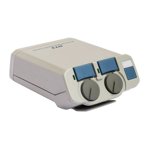
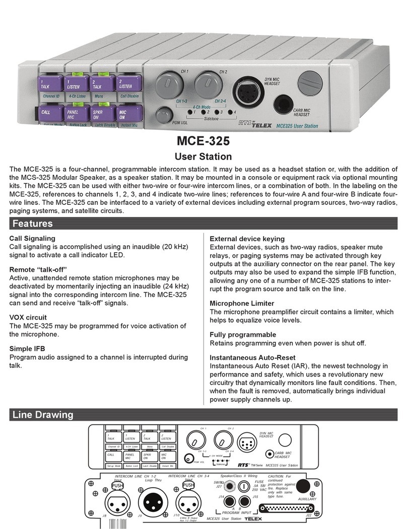
RTS Two-Wire Intercom RM-325 User manual

USER MANUAL
RM-325
Rack Mount Intercom Station
9350-7491-000 Rev B 3/98
PGM
Volume
DYN MIC
Headset
CARB MIC
Headset
RM-325 User Station
™
CH 2
Volume
CH 1
Volume
Sidetone
1
CallTalk Off
1
Talk 2
Talk
™

PROPRIETARY NOTICE
The RTSTM product information and design disclosed
herein were originated by and are the property of Telex
Communications, Inc. Telex reserves all patent,
proprietary design, manufacturing, reproduction, use and
sales rights thereto, and to any article disclosed therein,
except to the extent rights are expressly granted to others.
COPYRIGHT NOTICE
Copyright 1995 by Telex Communications, Inc.. All
rights reserved. Reproduction in whole or in part without
prior written permission from Telex is prohibited.
UNPACKING AND INSPECTION
Immediately upon receipt of the equipment, inspect the
shipping container and the contents carefully for any
discrepancies or damage. Should there be any, notify the
freight company and the dealer at once.
WARRANTY INFORMATION
RTSTM products are warranted by Telex Communications,
Inc. to be free from defects in materials and workmanship
for a period of three years from the date of sale.
The sole obligation of Telex during the warranty period is
to provide, without charge, parts and labor necessary to
remedy covered defects appearing in products returned
prepaid to Telex. This warranty does not cover any defect,
malfunction or failure caused beyond the control of Telex,
including unreasonable or negligent operation, abuse,
accident, failure to follow instructions in the Service
Manual or the User Manual, defective or improper
associated equipment, attempts at modification and repair
not authorized by Telex, and shipping damage.
To obtain warranty service, follow the procedures entitled
"Procedure For Returns" and "Shipping to Manufacturer
for Repair or Adjustment".
This warranty is the sole and exclusive express warranty
given with respect to RTSTM products. It is the
responsibility of the user to determine before purchase that
this product is suitable for the user's intended purpose.
ANY AND ALL IMPLIED WARRANTIES,
INCLUDING THE IMPLIED WARRANTY OF
MERCHANTABILITY ARE LIMITED TO THE
DURATION OF THIS EXPRESS LIMITED
WARRANTY.
NEITHER TELEX NOR THE DEALER WHO
SELLS RTSTM PRODUCTS IS LIABLE FOR
INCIDENTAL OR CONSEQUENTIAL DAMAGES
OF ANY KIND.
CUSTOMER SUPPORT
Technical questions should be directed to:
Customer Service Department
RTS/Telex,
2550 Hollywood Way, Suite 207
Burbank, CA 91505 U.S.A.
Telephone: (818) 566-6700
Fax: (818) 843-7953
RETURN SHIPPING INSTRUCTIONS
PROCEDURE FOR RETURNS
If a repair is necessary, contact the dealer where this unit
was purchased.
If repair through the dealer is not possible, obtain a
RETURN AUTHORIZATION from:
Customer Service Department
Telex Communications, Inc.
Telephone: (800) 828-6107
Fax: (800) 323-0498
DO NOT RETURN ANY EQUIPMENT DIRECTLY
TO THE FACTORY WITHOUT FIRST
OBTAINING A RETURN AUTHORIZATION.
Be prepared to provide the company name, address,
phone number, a person to contact regarding the repair,
the type and quantity of equipment, a description of the
problem and the serial number(s).
SHIPPING TO MANUFACTURER FOR REPAIR OR
ADJUSTMENT
All shipments of RTSTM products should be made via
United Parcel Service or the best available shipper,
prepaid. The equipment should be shipped in the original
packing carton; if that is not available, use any suitable
container that is rigid and of adequate size. If a substitute
container is used, the equipment should be wrapped in
paper and surrounded with at least four inches of
excelsior or similar shock-absorbing material. All
shipments must be sent to the following address and must
include the Return Authorization.
Factory Service Department
Telex Communications, Incorporated
West 1st Street
Blue Earth, MN 56013 U.S.A.
Upon completion of any repair the equipment will be
returned via United Parcel Service or specified shipper
collect.
RM-325 User Manual 2
Table of Contents
DESCRIPTION AND SPECIFICATIONS ............................................5
DESCRIPTION .......................................................5
GENERAL ........................................................5
FEATURES .......................................................5
SPECIFICATIONS......................................................6
TW System Specifications ................................................6
RM-325 General Specifications .............................................6
RM-325 Connectors ...................................................6
INSTALLATION ........................................................7
Configuration Jumper and DIP Switch Precheck ......................................7
Channel 1 and 2 Listen Disables (W1 & W2) ......................................7
Program Assignment (W3 & W4) ............................................7
Stereo/Monaural Headset Select (W5) ..........................................7
Audible Alert Option (X1) ................................................8
Channel Power Source Select (X2)............................................8
CARB MIC Headset Jack Setting (X3) .........................................8
Call Send Disable (S4-1) .................................................8
Latch Disable (S4-2 & S4-5) ...............................................8
Channel 1 and 2 Talk Disable (S4-3 & S4-4) ......................................8
Talk-off Transmit Enable (S4-6) .............................................8
Talk-off Receive Enable (S4-8) .............................................9
Mounting ...........................................................9
Intercom Channel and Power Connections..........................................9
Standard TW Connection.................................................9
Connection to a Source Assign Panel ..........................................9
Channel 2 Power when using TW Power Supplies .................................10
Supplying Local Power when Using TW Power Supplies .............................10
Channel Connections when using all Locally Powered Intercom Stations .......................10
Distributed Power from a Non-TW Power Source ...................................10
Program Input Connections.................................................10
Headset Connections ....................................................11
Remote Mic Switch Connection ..............................................11
Unswitched, Unbalanced Mic Audio Output ........................................11
Remote Footswitches for Talk On/Off ...........................................11
Sidetone Adjustment ....................................................11
Installation Notes ......................................................11
Choosing Headsets or Handsets.............................................11
Headphone Sound Isolation .............................................12
RM-325 User Manual 3

Isolation, Headset Microphones...........................................12
Cabling Requirements..................................................12
Wire Size ......................................................12
Grounding ......................................................12
Signal ........................................................13
RM-325 OPERATION .....................................................15
Listen Volumes .......................................................15
Talking to an Intercom Channel ..............................................15
Mic On/Off Switch .....................................................15
Sending Call Signals ....................................................15
Receiving Calls .......................................................15
Sending a Talk-off Signal..................................................16
Receiving Talk-off Signals .................................................16
REPLACEMENT PARTS ...................................................17
Where To Obtain Parts ...................................................17
Mechanical Parts ......................................................17
Electrical Parts .......................................................17
4RM-325 User Manual
List of Figures
Figure 1. RM-325 Front and Rear Panel Reference View ....................................5
Figure 2. Internal Jumpers and Switches ............................................8
Figure 3. Standard 2-channel TW Intercom Cable Wiring Diagram ..............................9
Figure 4. Termination plug for 2 intercom channels when all stations are locally powered ..................10
Figure 5. Termination / power plug for 1 intercom channel , with distributed power from a non-TW power source .....11
Figure 6. Optional Mounting Configurations .........................................14
Figure 7. Final Assembly, RM-325...............................................21
Figure 8. PC Board Assembly, RM-325 ............................................22
Figure 9. Schematic, RM-325, Sheet 1 of 2 ..........................................23
Figure 10. Schematic, RM-325, Sheet 2 of 2..........................................24
List of Tables
Table 1. Internal Jumpers and Default Settings .........................................7
Table 2. Internal DIP Switches and Default Settings .......................................7
Table 3. Environmental Noise, Sound Pressure Level At 10 Meters..............................12

1 DESCRIPTION AND SPECIFICATIONS
1.1 DESCRIPTION
1.1.1 GENERAL
The RM-325 is a two-channel intercom user station for
the RTS TW Intercom System. It is designed for use with
a headset, and it can be placed on a desktop, or rack
mounted with optional rack mount hardware.
1.1.2 FEATURES
•Talk Features: There is a separate talk button with
talk-on indicator for each channel. Talk buttons
feature dual-action, momentary/latching talk
operation: a button may be pressed and held to talk,
then released when finished, or the button may be
tapped once to turn talk on and then tapped again to
turn talk off. Latching operation may be
independently deactivated for each channel via an
internal DIP switch. The channel 1 and 2 talk buttons
may also be independently disabled via internal DIP
switches. Additionally, there is a an external talk
switch input (for footswitch etc.) for each channel via
the Aux connector.
•Listen Features and Headsets: There is a separate
listen volume control for each channel, and a listen
volume control for the program input. The RM-325
accepts a stereo, dynamic-mic headset or a monaural,
carbon-mic headset. Default operation is set for
stereo listen, with channel 1 assigned to left
headphone, channel 2 to right headphone, and
program input to both headphones. Internal jumpers
permit all signals to be combined for monaural
listening. Internal jumpers also permit the program
audio to be assigned left or right when using a stereo
headset.
•Microphone and Microphone Switch Features: The
Dynamic-mic headset connector features a balanced,
dynamic mic input, and a mic on/off switch input. A
remote mic on/off switch may also be connected via
the Aux connector. There is an internal mic-sensing
circuit for the carbon-mic headset jack, which
activates the mic circuit when the carbon mic is on.
An internal jumper can configure the carbon mic
input exclusively for use as a mic on/off switch input
(monaural headphone output is supported in either
case). The microphone audio is available as an
unswitched (hot, or always on) unbalanced output at
the Aux connector.
•Talk-off (Mic Kill) Signaling: the RM-325 can send
and receive Talk Off signals. Talk-off send and
receive can be independently enabled/disabled via
internal DIP switches.
•Call Signaling: There is a call button and indicator,
and the RM-325 can send and receive call signals.
There is also an internal setup switch to disable call
send.
•Program Input: Balanced program audio may be
input via the 1/4-inch stereo phone jack (PGM) or via
the AUX connector.
•Line/Local Power Options: By default, the RM-325
receives operating power from intercom channel 1.
Alternatively it may be configured to receive power
from channel 2 or from a local, 24 VDC power
source connected to the AUX connector.
•Sidetone: There is a separate sidetone control for
each intercom channel. These adjust the level of the
station operator’s own voice in the headphones when
talking.
RM-325 User Manual 5
PGM
Volume
CH 2
Volume
CH 1
Volume
Sidetone
12
Talk Off
DYN MIC
Headset
CARB MIC
Headset
RM-325 User Station
Call 1
Talk 2
Talk
™
TELEX COMMUNICATIONS, INC.
MADE IN USA
AUXPGMLINE LOOPLINE INPUT
PUSH
Figure 1. RM-325 Front and Rear Panel Reference View

1.2 SPECIFICATIONS
1.2.1 TW System Specifications
DC Operating Limits (station to power supply):
About 5,000 ft. (1.5 km) with #22 AWG wire
Audio Operating Limits (locally powered stations):
About 10,000 ft. (3 km) with low-capacitance cabling
System Capacitance:
0.3
m
F, maximum (10,000 ft. [3 km] cable at 30 pF/ft.)
Intercom Channels:
Station Output Level: 0.7 Vrms (0 dBu) nominal
Channel Terminating Impedance: 200
W±
5%
Station Bridging Impedance: greater than 10,000
W
Current Source:
Transfer Ratio: 3.3 mA/V = 3.3 millisiemans
Output:
±
5 mA into 200
W
,
±
1 Vpeak (limiter threshold)
Call Signalling:
Send: 20 kHz
±
100 Hz, 0.3 Vrms nominal
Receive: 20 kHz
±
200 Hz, 100 mVrms
Talk- Off Signalling:
Send: 24 kHz
±
100 Hz, 0.3 Vrms nominal
Receive: 24 kHz
±
200 Hz, 100 mVrms
1.2.2 RM-325 General Specifications
Power Requirements, Channel Powered RM-325:
30 VDC nominal (standard TW line), 60 to 100 mA
Power Requirements, Locally Powered RM-325:
24 VDC nominal, 60 to 100 mA
Environmental Requirements:
Storage: -40
°
Cto125
°
C; 0% to 95% humidity,
non-condensing
Operating: 0
°
Cto50
°
C; 0% to 95% humidity,
non-condensing
Dimensions:
1.72" (44 mm) high x 8.2" (208 mm) wide x 8" (203 mm)
deep
Weight:
2 lbs 12 oz (1.23 kg)
Noise Contribution:
less than -75 db on the line
Common Mode Rejection Ratio:
greater than 40 dB from the line
Program Input:
Maximum Input Level: 20 dBu
Nominal Input Level: -10 to +8 dBu
Frequency Response: 100 Hz to 12 kHz
±
3dB
Headphone Amplifier
Voltage Gain: 30
±
3 dB from the line
Maximum Output: 150 mW into 50
W
Frequency Response: 100 Hz to 8 kHz
±
3 dB nominal
Output Voltage Level: 8 volts peak-to-peak
Headphone Impedance: 50 to 600
W
Sidetone:
20 dB minimum range, adjustable
Microphone Preamplifier:
Maximum Voltage Gain: 54 dB
Frequency Response: 100 Hz to 8 kHz, nominal
Input Impedance: 1,000
W
, balanced
Limiter Range: 30 dB
Total Harmonic Distortion:
Less than 0.2% nominal at Channel output
1.2.3 RM-325 Connectors
Auxiliary Connector
Type: DB-15F
Pin 1: Program input low
Pin 2: Program input high
Pin 3: Unswitched mic output high
Pin 4: Foot switch in, channel 1
Pin 5: Foot switch in, channel 2
Pin 6: Local power (+24 VDC)
Pin 7: Remote mic switch in
Pin 8: Not Used
Pin 9: Common
Pin 10: Common
Pin 11: Common
Pin 12: Foot switch channel 1 common
Pin 13: Foot switch channel 2 common
Pin 14: Local power common
Pin 15: Remote mic switch common
CARB MIC Headset Connector
Type: ¼”, 3-Conductor Phone Jack
Tip: Microphone input high (or mic switch contact
Ring: Headphone high
Sleeve: Common
DYN-MIC Headset Connector
Type: XLR-6F 6-Pin Female Audio Connector
Pin 1: Headset dynamic microphone low
Pin 2: Headset dynamic microphone high
Pin 3: Headphone and mic switch common
Pin 4: Headphone left high
Pin 5: Headphone right high
Pin 6: Remote microphone switch contact
Intercom Line Input Connector
Type: XLR-3F 3-Pin Female Audio Connector
Pin 1: Common
Pin 2: Intercom channel 1 audio and power
Pin 3: Intercom channel 2 audio
Intercom Line Loop Connector
Type: XLR-3M 3-Pin Male Audio Connector
Pin 1: Common
Pin 2: Intercom channel 1 audio and power
Pin 3: Intercom channel 2 audio
Program Input Connector
Type: 1/4", 3-Conductor Phone Jack
Tip: Program input high
Ring: Program input low
Sleeve: Common
6RM-325 User Manual

2 INSTALLATION
2.1 Configuration Jumper and DIP
Switch Precheck
Before making connections, check that the internal
jumpers and DIP switches are properly configured for
your intended use. The descriptions and default settings
are summarized below and in Tables 1and 2. For internal
access, remove the four long screws (Figure 7, item 11)
and remove the top cover. Locations of jumpers and DIP
switches are shown in Figure 2.
2.1.1 Channel 1 and 2 Listen Disables (W1 & W2)
Normally, listen is enabled for both channels 1 and 2.
Listen may be disabled for either channel by changing the
setting of W1 or W2.
This option could be used, for example, when you want to
use the left side of a stereo headphone exclusively for
program audio input and the right side for one channel of
intercom audio. In this case you would:
1. Set W5 for stereo operation (default).
2. Set W1 to “off” to disable channel 1 intercom listen.
3. Set DIP switch S4-4 to “on” to disable channel 1 talk.
4. Set W3 for left headphone program and set W4 to
disable right headphone program.
2.1.2 Program Assignment (W3 & W4)
Normally, the RM-325 is set for stereo headphone
operation (W5 jumper pins 1&2 shorted) and the program
input is assigned to both right and left headphones via
jumpers W3 and W4. You can disable program listen in
either headphone (or both) by changing the W3 and W4
settings. For monaural operation (W5 jumper pins 2&3
shorted) set W3 to “pins 1&2 shorted”, and set W4 to
“pins 2&3 shorted”.
2.1.3 Stereo/Monaural Headset Select (W5)
In stereo mode, with a stereo dynamic-mic headset
attached, intercom channel 1 will be heard in the left
headphone, and channel 2 will be heard in the right. The
program will be heard in the left and/or right headphone
depending on the settings of W3 and W4 (it is heard in
both the left and right headphones by default).
To use a monaural or single-sided headset with the DYN
MIC jack, set jumper W5 so that pins 2&3 are shorted.
Also, set the W4 jumper to “Pins 2&3 shorted”: this will
prevent possible loss of the program signal in the
headphones due to cancellation effects of the internal
headphone amplifiers.
If you use a carbon-mic headset, keep the default stereo
settings for W3, W4 and W5. There is an internal mixing
amplifier which automatically mixes the right and left
stereo headphone signals for the monaural CARB Mic
Headset jack.
RM-325 User Manual 7
Jumper
Number Jumper Function Default
Setting
W1 CH1 Listen:
Pins 1&2 shorted: listen enabled
Pins 2&3 shorted: listen disabled
1&2
shorted
W2 CH2 Listen:
Pins 1&2 shorted: listen enabled
Pins 2&3 shorted: listen disabled
1&2
shorted
W3 Program Assign to Left Headphone
or Mono Mix
Pins 1&2 shorted: enabled
Pins 2&3 shorted: disabled
1&2
shorted
W4 Program Assign to Right Headphone
Pins 1&2 shorted: enabled
Pins 2&3 shorted: disabled
1&2
shorted
W5 Stereo/Mono Operation:
Pins 1&2 shorted: stereo
Pins 2&3 shorted: mono
1&2
shorted
X1 Audible Alert Option 1 & 2
open
X2 Channel Power Source Select:
Pins 1&2 shorted: channel 2 power
Pins 2&3 shorted: channel 1 power
2&3
shorted
X3
CARB MIC
Jack Setting:
Pins 1&2 shorted: carbon mic
Pins 2&3 shorted: mic switch only
1&2
shorted
Table 1. Internal Jumpers and Default Settings
Dip
Switch
Number
Switch Function Default
Setting
S4-1 Call Send Disable
Off (Open): call send enabled
On (Closed): call send disabled
Off
S4-2 Channel 2 Talk Latching Disable
Off (Open):Ch 2 talk latching enabled
On (Closed): Ch 2 talk latching disabled
Off
S4-3 Channel 2 Talk Disable:
Off (Open): Ch 2 talk enabled
On (Closed): Ch 2 talk disabled
Off
S4-4 Channel 1 Talk Disable:
Off (Open): Ch 1 talk enabled
On (Closed): Ch 1 talk disabled
Off
S4-5 Channel 1 Talk Latching Disable
Off (Open):Ch 1 talk latching enabled
On (Closed): Ch 1 talk latching disabled
Off
S4-6 Talk-Off Transmit Enable
Off (Open): disabled
On (Closed): enabled
On
S4-7 Not used Off
S4-8 Talk-Off Receive Enable:
Off (Open): disabled
On (Closed): enabled
On
Table 2. Internal DIP Switches and Default Settings

2.1.4 Audible Alert Option (X1)
A high-impedance, piezoelectric buzzer may be
connected between the X1 terminals for audible alert on
incoming call.
2.1.5 Channel Power Source Select (X2)
The X2 jumper determines which (if any) intercom
channel the RM-325 will be powered from. Normally, this
is channel 1 and no change should be required. There are
some situations, however, where you may need to power
the RM-325 from channel 2, or from a local power
source. See “Intercom Channel and Power Connections”,
page 9, for details.
2.1.6 CARB MIC Headset Jack Setting (X3)
The CARB MIC Headset jack on the front panel is
normally used for a monaural, carbon-mic headset. If the
headset is equipped with a mic on/off switch, this can be
used with the remote mic switch feature of the RM-325.
See “Mic On/Off Switch” in the operation instructions,
page 15. If the CARB MIC Headset jack is not used for a
headset, it can be converted to a remote mic on/off switch
jack for use with the remote mic switch feature. By
default, jumper X3 is set for carbon mic input. When X3
is set for mic on/off switch input, a switch contact closure
between the tip and sleeve contacts on the CARB MIC
jack will activate the mic circuit.
2.1.7 Call Send Disable (S4-1)
Normally, the RM-325 can send call signals. This feature
may be disabled by setting S4-1 to the “On” position.
2.1.8 Latch Disable (S4-2 & S4-5)
The talk buttons feature dual-action, momentary/latching
operation. For momentary operation, a talk button may be
pressed and held to talk, and will turn off when released.
For latching operation, a talk button may be tapped to turn
it on and then tapped again to turn it off. In some
applications it may be desirable to disable the latching
feature. This can be done independently for the channel 1
and 2 talk buttons via the S4-2 and S4-5 DIP switches
2.1.9 Channel 1 and 2 Talk Disable (S4-3 & S4-4)
Normally, the talk buttons for channels 1 and 2 are
enabled. They may be disabled via DIP switches S4-3 and
S4-4.
2.1.10Talk-off Transmit Enable (S4-6)
The RM-325 can send a special, inaudible signal to turn
off the microphones on all stations on a channel that are
equipped to receive this signal. This feature is useful
when an unattended intercom station has been left with a
mic or talk button in the on position and is picking up
8RM-325 User Manual
DS3 DS1 DS2
W5 W3
W1
W2
W4
S4
C41
J5
J6
J3
12
12
X2
X3
X1
1
8
ON OFF
J2
3
1
3
1
3
1
J1
1
2
3
X2
X3
1
1
2
2
3
3
Figure 2. Internal Jumpers and Switches

background noise. In some applications, it may be
desirable to disable the talk-off transmit feature.
2.1.11Talk-off Receive Enable (S4-8)
The RM-325 can also receive the special talk-off signals
discussed above. In some cases, it may be desirable to
disable this receive capability. This will prevent
accidental deactivation of the RM-325 station operator’s
talk buttons during critical communications.
2.2 Mounting
The RM-325 can be used on a desktop, or
console-mounted, or rack-mounted. Some possible
mounting configurations and the required optional
mounting hardware are shown in Figure 6, page 14. When
mounting the RM-325, always allow adequate room
behind the unit for cable access.
2.3 Intercom Channel and Power
Connections
There are several methods to connect the RM-325 to
intercom channels and power. Whichever method is used,
you must assure that the RM-325 receives operating
power, and also that the intercom channels are properly
terminated.
2.3.1 Standard TW Connection
You can connect the RM-325 directly to a PS-15 or PS-31
power supply using a standard 2-channel TW intercom
cable (Figure 3). Connect from the power supply’s
OUTPUT to the RM-325’s LINE INPUT. You can then
connect another 3-pin cable to the LINE LOOP connector
on the RM-325 and continue on to another RM-325 or
other intercom station. When you connect stations in this
manner, all stations receive operating power on channel 1.
And, both intercom channels will be properly terminated
by the TW power supply.
The RM-325 can also be connected to a TW5W or
TW7W splitter, which is itself connected directly to a TW
power supply. Again, you use a standard 2-channel TW
intercom cable. The RM-325 will receive operating power
on channel 1, and both intercom channels will be properly
terminated.
2.3.2 Connection to a Source Assign Panel
If TW power supplies are used, but an SAP Source
Assign Panel is used to assign channels to the RM-325,
there can be occasions when the RM-325 will not receive
operating power on channel 1 as required, but will still be
properly terminated on both channels.
Example: Suppose the RM-325 is connected to a SAP612
Source Assign Panel, and there are three PS15 Power
Supplies connected to the SAP612. The SAP612 has
twelve connectors on the back, for connecting RM-325’s
and other intercom stations. On the SAP612 front panel,
there are two selector switches for each of the twelve
connectors, and you can select any two PS15 channels to
route to each connector. Since the PS15 power supplies
only provide power on their #1 channels, the SAP612
selector switches could let you select combinations where
RM-325 User Manual 9
Pair 1
Pair 2
CableType: 22 AWG stranded copper, 2-pair twisted-wire, with shield
and drain wire (Belden #8723 or equivalent)
Standard cables are generally constructed using a female connector at one end
and a male connector at the other end.This allows several cables to be
interconnected to create longer cable runs if neede.Also, TW intercom stations
typically provide both a male and female XLR connector for conference lines.This
permits loop-through connection of several intercom stations using the standard
cables.
Denotes shield.
Pin 3 Pin 3
Pin 2 Pin 2
Pin 1 Pin 1
3-Pin Female
XLR Connector 3-Pin Male
XLR Connector
Pin 1: Common
Pin 2: Channel 1
Pin 3: Channel 2
Figure 3. Standard 2-channel TW Intercom Cable Wiring Diagram

power would be supplied on channel 2 of a connector, or
not at all. In this case, you have 3 alternatives:
1) Assign different channels to the RM-325 so that it
will receive power on channel 1
2) Reconfigure the RM-325 to receive power on channel
2. See “Channel 2 Power when using TW Power
Supplies”, below.
3) Reconfigure the RM-325 for local power. See
“Supplying Local Power when Using TW Power
Supplies”, below.
2.3.2.1 Channel 2 Power when using TW Power
Supplies
To power the RM-325 from channel 2, carefully and
completely cut the circuit trace between X2 pins 2&3.
Then solder a jumper between X2 pins 1&2. The RM-325
will now receive power from channel 2, and both
channels will be terminated by the TW power supply.
2.3.2.2 Supplying Local Power when Using TW
Power Supplies
To use a local power source, carefully and completely cut
the circuit trace between X2 pins 2&3, and leave all X2
pins unconnected.
Connect your own local 24 VDC power supply to the
AUX connector. (Use a well filtered power source, 60 to
100 mA.) Pin 6 is +DC. Pin 14 is Common.
The RM-325 will now receive power from the local
power supply, while both channels will be terminated by
the TW power supply. Note that since the RM-325 is not
drawing any power from the channels, you should not
include this station if you are computing total power
consumption for the TW power supply.
2.3.3 Channel Connections when using all Lo-
cally Powered Intercom Stations
There may be a few occasions where it makes sense to
locally power all of your intercom stations. For example,
your intercom stations may be widely dispersed about a
large building complex, where stations are separated by
anywhere from 1000 ft to 10,000 ft. Due to wire
resistances, it is not practical to supply power over the
intercom channels for these distances. However, the audio
and signals can operate over this range. The solution is to
supply power separately to each station.
When all stations are locally powered, and there is no TW
power supply in the system, a line termination will have to
be inserted at one (and only one) location in in each intercom
channel. It doesn’t matter where, but it is important that there
is only only one termination per channel. Figure 4shows
how to construct a termination plug for this purpose. Plug the
termination plug into the intercom LINE INPUT connector
of only 1 intercom station. Then plug a standard 2-channel
TW cable into the LINE LOOP connector to connect to
another intercom station.
2.3.4 Distributed Power from a Non-TW Power
Source
It is possible to power several TW intercom stations from
a single, non-TW power source, such as a battery. This
might be an ideal setup for a small, portable system where
AC power is not available. This method uses channel 1
only to connect the non-TW power supply. Audio on
channel 1 will be unusable. Channel 2, however, will still
be operational. Also, channel 2 will require a terminating
impedance, since this is not supplied by the non-RTS
power supply.
Figure 5shows how to construct a termination plug and also
connect power. Plug the power/termination plug into the
intercom LINE INPUT connector of only 1 intercom station.
Then plug a standard 2-channel TW cable into the LINE
LOOP connector to connect to another intercom station.
2.4 Program Input Connections
You can connect a balanced or unbalanced audio source
to either the PGM input connector or to the AUX
connector. Refer to the specifications (page 6) for
pin-outs of these connectors.
10 RM-325 User Manual
+
+
23
WIRES MUST NOT TOUCH!
3-Pin Male
XLR Connector
200
Ohms
++
10µ
Capacitors 10µ, 50V Electrolytic
50V
Pin 3
Ch 2 Audio
Pin 2
Ch 1 Audio
Pin 1
Common
To an Intercom Station
LINE INPUT Connector
{
Resistors 200 Ohms, 1/8 Watt
Figure 4. Termination plug for 2 intercom chan-
nels when all stations are locally powered

2.5 Headset Connections
Connect a stereo (default) or monaural headset to the
DYN MIC Headset connector. Or, connect a monaural,
carbon-mic headset to the CARB MIC headset connector.
Refer to the specifications (page 6) for pin-outs of these
connectors.
2.6 Remote Mic Switch Connection
If your headset is equipped with a mic on/off switch, you
can probably use it with the remote mic switch feature of
the RM-325. See “Mic On/Off Switch” in the operation
instructions, page 15.
If your headset does not have a mic switch, but you want
to use this feature, you can connect a remote mic switch
to the AUX connector. Or, you can change the setting of
the X3 jumper (page 8) and then use the CARB MIC
Headset jack for a remote mic switch. Refer to the
specifications (page 6) for pin-outs of these connectors.
2.7 Unswitched, Unbalanced Mic Audio
Output
The mic audio is available at the AUX connector for
connection to an external device, such as a PA amplifier.
The mic audio at this output is always on and will not be
switched off my the talk buttons. Refer to the
specifications (page 6) for unswitched mic pin numbers.
2.8 Remote Footswitches for Talk
On/Off
There are separate footswitch inputs for channel 1 and 2
at the AUX connector. A switch contact closure at either
of these inputs will have the same effect as turning on the
talk button for that channel. Refer to the AUX connector
specifications (page 6) for footswitch pin numbers.
2.9 Sidetone Adjustment
The sidetone trimmers control the level of the station
operator’s own voice in the headphones while talking.
Normally, when using headphones that do not fully cover
the ears, no sidetone level is required, and the sidetone
trimmers should be adjusted to minimize the operator’s
voice level. This also lessens the risk of feedback between
the headphones and microphone. When using headphones
that completely cover the ears, the sidetone level may be
increased to overcome the muffled sensation when
talking. Use a small flat-blade screwdriver through the
sidetone trimmer access holes in the front panel to
increase or decrease the voice level while talking on the
intercom channels. Note that there is a separate trimmer
for each channel.
2.10 Installation Notes
2.10.1Choosing Headsets or Handsets
The RM-325 accepts a wide variety of headsets and
handsets. Headset or handset choice depends on
operating environment, operating requirements, and
personal taste.
Table 3shows typical operating environments and the
level of background noise present. The background noise
is measured using a Sound Pressure Level (SPL) meter,
which measures the sound pressure level in decibels. SPL
is useful for measuring environmental background noise,
comparing headphone efficiency, and predicting whether
speech communication is possible.
•A very noisy/loud environment usually requires
headphones that prevent outside sound from leaking
in (again, good acoustic isolation), headphones that
can produce a loud, clear sound, and noise canceling
microphones.
•Understanding speech in a noisy environment
requires that the sound from the headphones is as
loud or louder than the sound leaking into the
headphones from the noisy environment.
•In general, the loudness of a headphone depends
upon its ability to absorb power at a given voltage
(power=voltage squared divided by the impedance)
and the efficiency of its design. Practically, the
RM-325 User Manual 11
+
23
WIRES MUST NOT TOUCH!
3-Pin Male
XLR Connector
Capacitor 10µ, 50V Electrolytic
To an Intercom Station
LINE INPUT Connector
{
{
Resistor 200 Ohms, 1/8 Watt
Pin 3
Ch 2 Audio
Pin 2
+18 to
+24 VDC
+18 to
+24 VDC
Pin 1
TO POWER
SUPPLY
200 Ohms
+
10µf/50V
Common
Common
Figure 5. Termination / power plug for 1 intercom
channel , with distributed power from a non-TW
power source

impedance has a larger effect with present day
headsets.
•Low impedance headphones are louder, causing the
RM-325 to draw more current from the power
supply. High impedance headphones are not as loud,
drawing less current from the power supply. The
RM-325 design range of impedances for the
headphone part of the headset is 25Ωto 600Ω.
•Efficiency is the amount of SPL (Sound Pressure
Level) produced for a given electrical input power.
2.10.1.1Headphone Sound Isolation
The ability of headphones to shut out unwanted
environmental noise varies from none (0 dB isolation) to
about 1/8th as loud (30 dB isolation). The degree of
isolation depends both on the design of the headset and
the frequency content of the environmental noise.
Lightweight, "open" headsets have almost no (0 dB)
isolation. The trade off is that lightweight headsets are
very comfortable and can be worn for long periods (8 to
12 hours) without physical discomfort from the earmuffs
or headband. Because there is no isolation, care must be
taken that the sound signals from lightweight headsets are
not unintentionally leaked into microphones. In general,
the comfort of headsets depends upon their weight,
padding and design.
2.10.1.2Isolation, Headset Microphones
In high noise environments, the headset microphone
should be a noise canceling type.
2.10.2Cabling Requirements
2.10.2.1Wire Size
It may be necessary to overcome power losses by
increasing conductor size over long runs (more than one
kilometer). Normal conductor size is #22 AWG. The
maximum allowable loop resistance is determined by the
power supply voltage, the loop current and the user
station minimum operating voltage. The maximum loop
resistance equals the difference of the power supply
voltage and the minimum operating voltage divided by
the maximum loop current (power required by the user
station(s)).
Example: A headset station (with 25Ωheadphones) uses
up to 70 mA. The power supply voltage is 26 VDC and
the user station minimum operating voltage is 18 VDC.
Then the maximum allowable loop resistance is:
(26 - 18) V/0.07A=114Ω
This corresponds to an operating distance of 1.1
kilometers (3,562 feet) for a #22 AWG wire pair using a
single user station with 25 ohm headphones. Data for
these calculations can be found in standard electrical wire
tables.
2.10.2.2Grounding
System circuit ground should not be directly connected to
“earth” or “chassis” ground (where directly means a
connection an ohmmeter would show).
In order to prevent a buildup of voltage across the system
capacitance, the power supply has a bleeder resistor to
chassis ground (22 kΩ). If the system has no RTS
Systems power supply, such a bleeder resistor should be
supplied at a central point in the system.
The basic benefit of not "earth" grounding the RTS
System circuit return is that it permits continued operation
during an accidental system ground fault. This accidental
grounding can happen as the result of a pinched wire or a
scraped cable that has been pulled across a sharp edge. A
single accidental ground can be tolerated by the system
until the fault can be cleared and (with luck) before a
second ground fault can cause noise or overload. Another
benefit of not "earth" grounding the circuit return is that it
prevents the introduction of noise through "earth" currents
from other equipment. If the RTSTM circuit ground
conducts these currents, it is likely that they will be heard
as interfering noise on the communication line.
12 RM-325 User Manual
SOURCE SPL
Aircraft 120 dB to 160 dB
Orchestra, 75 piece,
(peaks) or Pipe Organ,
(peaks)
140 dB
Rock Concert 110 dB to 140 dB
Piano, (peaks) 120 dB
Blaring Radio 110 dB
Centrifugal Ventilating
Fan 110 dB
Auto on Highway 100 dB
Vane axial Ventilating
Fan 90 dB
Voice, Shouting 90 dB
Factory 75 dB
Voice, Conversational 70 dB
Residence 45 dB
Television Studio 25 dB to 35 dB
Voice, Whisper 30 dB
Table 3. Environmental Noise, Sound Pressure
Level At 10 Meters

2.10.2.3Signal
Two conductors are required for a one channel system,
and three conductors are required for a two channel
system. Shielded cable is recommended.
Two channel applications may use either standard
microphone cable (for convenience) or two-twisted-pair
cable (less expensive than microphone cable). Standard
wire size for the system is #22 gauge wire for
interconnection. For permanent installations it is
recommended that each channel should have individually
shielded twisted pair of at least #22 gauge wire; such as
Belden #8723 or 9402 for 2 channels. This will reduce
interference and help maintain a low crosstalk figure
between channels. Connections are as follows:
First shielded pair: connect shield and black to common
(pin 1 in two channel system), connect color to channel 1
(pin 2 in two channel system);
Second shielded pair: connect shield and black to
common (pin 1 in two channel system), connect color to
channel 2 (pin 3 in two channel system).
The audio signal line level is maintained between -10 dBu
and 0 dBu (between 0.24 and 0.77 Vrms). These levels
are low enough to prevent crosstalk into other equipment
(such as TV cameras) yet high enough to reduce external
interference to the TW System.
The 200Ωline impedance is high enough to allow
communication over line lengths of 1.6 kilometers (one
mile) and low enough to permit an adequate speech
bandwidth with 3.2 kilometers of accumulated cable. In
most systems the 200Ωimpedance gives a high fidelity
bandwidth with low losses.
When using equipment in rain or conditions of excessive
moisture, always protect the equipment with plastic
covers and make sure all cable connectors are lifted out of
mud, snow or moisture and protected with plastic or tape.
Water mud and snow in connectors can cause
considerable hum.
RM-325 User Manual 13

14 RM-325 User Manual
Side-By-Side Rack Mount Configuration Using an MCP1 Rack Mount Kit
Single-unit Rack Mount Configuration Using an MCP2 Rack Mount Kit
Tandem Configuration Using an MCP4Tandem Mount Kit
Console Mount Configuration Using an MCP3 Console Mount Kit
Figure 6. Optional Mounting Configurations

3 RM-325 OPERATION
+There are several operating features that are
configured with internal jumpers and switches. If the
default settings for these are changed, your RM-325
may not operate exactly as described below. The
operating procedures describe the factory default
operation first, and then explain how the operation
could be affected by the internal settings.
3.1 Listen Volumes
If you are using a stereo dynamic-mic headset, adjust the
channel 1 level in the left headphone with the CH 1
Volume control; adjust the channel 2 volume in the right
headphone using the CH 2 Volume control. If you are
using a monaural, carbon-mic headset, the volume
controls adjust the channel 1 and 2 levels in the mono
mix.
If there is an external program source connected, adjust its
volume in the headphones with the PGM Volume control.
+If the RM-325 is reconfigured for a monaural,
dynamic-mic headset (page 7) the CH 1 and CH 2
controls adjust the level for each channel in the mono
mix.
+If either channel’s listen has been deactivated (page
7) you will not be able to hear or adjust volume for
that channel.
+Depending on how the program is assigned (page 7)
the PGM Volume control may adjust the program
level in the right headphone, the left headphone, or in
the mono mix.
3.2 Talking to an Intercom Channel
For momentary talk, press and hold the “1 Talk” or “2
Talk” button while talking. Then, release the button when
finished talking. While the button is held, the talk
indicator will be on.
For latching talk, tap a talk button to turn it on. Then, tap
it again to turn it off when you are finished talking. The
talk indicator will remain lit while the button is latched
on.
+If latching operation does not work for one or both
channels, it may have been disabled (page 8).
+If talk has been disabled for one or both channels
(page 8) you will not be able to talk to the affected
channel(s).
3.3 Mic On/Off Switch
If your headset includes a mic on/off switch, or if a
remote mic on/off switch has been connected to the
CARB MIC or AUX connector, you can use it to
remotely activate either or both talk buttons. Set up the
mic switch as follows:
1. Turn the mic switch on.
2. Tap one or both talk buttons to latch them on. The
talk light(s) should be on.
3. Turn the mic switch off. Now when you turn the mic
switch on, the talk buttons that you selected in step 2
will turn on.
4. To change which talk button(s) are activated by the
mic switch, repeat steps 1 and 2.
+You can manually activate either talk button when
the mic switch is off. As long as you turn that talk
button off before you activate the mic switch again,
your current mic switch settings will not be affected.
3.4 Sending Call Signals
Although you can activate a talk button and simply begin
talking on a channel, it is sometimes preferable to send an
inaudible, visual call signal first as follows:
1. Turn on the talk button for the channel that you want
to call.
2. Press and hold the Call button until a verbal response
is received, then release the Call button and begin
talking.
3. Turn off the talk button when you are finished.
+You cannot send call signals if call send has been
disabled (page 8).
3.5 Receiving Calls
When someone else sends a call signal on a channel, the
RM-325 Call indicator will flash red.
•If a talk button is also flashing, this means you must
activate that button to talk back.
•If no talk button is flashing, this means the talk
button is already on: simply begin talking.
Turn the talk key off when finished talking.
RM-325 User Manual 15

3.6 Sending a Talk-off Signal
The RM-325 can generate an inaudible signal which can
be used to deactivate the microphones on other intercom
stations connected to the intercom channel (works with
models BP-318, BP-325, BP-350, RM-325, MCE-325 and
MRT-327). This feature is useful when there is a
microphone activated on an unattended intercom station,
and it is causing noise on the intercom channel. To send a
Talk-Off signal:
1. Turn off both talk buttons.
2. Tap the CALL button three quick taps. The red
CALL indicator will turn on for a few seconds.
3. While the red CALL indicator is on, momentarily
press the talk button for the desired channel. This will
send the talk-off signal and turn off all remote
microphones on that channel.
+You cannot send talk-off signals if this feature has
been deactivated (page 8).
3.7 Receiving Talk-off Signals
If a talk button is on, and a talk-off signal is received on
that channel, the talk button will turn off.
+Talk-off signals will not be received if this feature
has been disabled (page 9).
16 RM-325 User Manual

4 REPLACEMENT PARTS
4.1 Where To Obtain Parts
Parts may be obtained directly from Telex at:
Telex/RTS Systems
9600 Aldrich Ave. So.
Minneapolis, MN 55420
800-828-6107
Fax: 800-323-0498
4.2 Mechanical Parts
FINAL ASSEMBLY
(Refer to Figure 4-1 for Item No. locations)
Item No. Description Part No.
1 Bezel, RM-325 9070-7491-000
2 Insert, 6 Pin Connector 2018-0077-00
3 Lightpipe, Call Button 4501-0062-00
4 Knob, Volume 2703-0037-00
5 Key Cap, Call 9150-6643-05
6 Key Cap, Talk 1 9150-6643-01
7 Key Cap, Talk 2 9150-6643-03
8 Stem, Switch 2705-0021-00
9 P.C. Board Assy. 9030-7491-00
see Fig. 4-2
10 Case, Extruded 9060-6260-00
11 Screw, Case 9160-6305-00
12 Screw, #4-40 x 3/8" 51845-039
13 Screw, Lock, #4-40 58421-000
14 Screw, M3 x 7.0 mm 16030D8
15 Panel, Rear RM-325 9080-7491-000
16 Valox Film, 0.010 Thk., 7.0" X
6.75" 1303-0009-00
17 Knob, Volume 2703-0034-00
18 Not Used
19 Not Used
20 Not Used
21 Not Used
22 Not Used
23 Not Used
24 Housing, Connector, 6 Pin 59958-006
25 Terminal 59958-200
4.3 Electrical Parts
CIRCUIT BOARD ASSEMBLY
(Refer to Figures 4-3 and 4-4)
Ref. No. Description Part No.
Heatsink 45020018-00
C1 Capacitor, EL, SM, 47
m
F, 10V 102884-215
C2 Capacitor, CM, SM, 100 pF, 50V 102879-204
C3 Capacitor, EL, SM, 47
m
F, 10V 102884-215
C4 Capacitor, CM, SM, 1000 pF, 50V 102881-327
C5 Capacitor, CM, SM, 1000 pF, 50V 102881-327
C6 Capacitor, CM, SM, 0.1
m
F, 50V 102881-351
C7 Capacitor, CM, SM, 0.1
m
F, 50V 102881-351
C8 Capacitor, CM, SM, 0.1
m
F, 50V 102881-351
C9 Capacitor, EL, SM, 47
m
F, 10V 102884-215
C10 Capacitor, CM, SM, 470 pF, 50V 102879-212
C11 Capacitor, CM, SM, 0.1
m
F, 50V 102881-351
C12 Capacitor, EL, SM, 22
m
F, 35V 1099R226-3G
C13 Capacitor, CM, SM, 0.01
m
F, 50V 102881-339
C14 Capacitor, CM, SM, 1000 pF, 50V 102881-327
C15 Capacitor, CM, SM, 10 pF, 50V 102879-271
C16 Capacitor, EL, SM, 1
m
F, 50V 102884-606
C17 Capacitor, CM, SM, 0.1
m
F, 50V 102881-351
C18 Capacitor, CM, SM, 100 pF, 50V 102879-204
C19 Capacitor, CM, SM, 100 pF, 50V 102879-204
C20 Capacitor, CM, SM, 100 pF, 50V 102879-204
C21 Capacitor, CM, SM, 10 pF, 50V 102879-271
C22 Capacitor, EL, SM, 22
m
F, 35V 1099R226-3G
C23 Capacitor, EL, SM, 22
m
F, 35V 1099R226-3G
C24 Capacitor, EL, SM, 22
m
F, 35V 1099R226-3G
C25 Capacitor, CM, SM, 100 pF, 50V 102879-204
C26 Capacitor, EL, SM, 22
m
F, 35V 1099R226-3G
C27 Capacitor, CM, SM, 100 pF, 50V 102879-204
C28 Capacitor, CM, SM, 100 pF, 50V 102879-204
C29 Capacitor, CM, SM, 10 pF, 50V 102879-271
C30 Capacitor, EL, SM, 22
m
F, 35V 1099R226-3G
C31 Capacitor, EL, SM, 22
m
F, 35V 1099R226-3G
C32 Capacitor, EL, SM, 22
m
F, 35V 1099R226-3G
C33 Capacitor, CM, SM, 100 pF, 50V 102879-204
C34 Capacitor, EL, SM, 1
m
F, 50V 102884-606
C35 Capacitor, EL, SM, 1
m
F, 50V 102884-606
C36 Capacitor, CM, SM, 1000 pF, 50V 102881-327
C37 Capacitor, CM, SM, 1000 pF, 50V 102881-327
C38 Capacitor, EL, SM, 1
m
F, 50V 102884-606
C39 Capacitor, CM, SM, 100 pF, 50V 102879-204
C40 Capacitor, EL, SM, 47
m
F, 10V 102884-215
C41 Capacitor, EL, RA, 4700
m
F, 35V 1513R478-4G
C42 Capacitor, EL, SM, 47
m
F, 10V 102884-215
C43 Capacitor, EL, SM, 47
m
F, 10V 102884-215
C44 Capacitor, CM, SM, 0.1
m
F, 50V 102881-351
C45 Capacitor, CM, SM, 0.1
m
F, 50V 102881-351
C46 Capacitor, EL, SM, 22
m
F, 35V 1099R226-3G
C47 Capacitor, CD, RA, 0.1
m
F, 500V 1510R104-2Q
C48 Capacitor, EL, 1000
m
F, 16V 51821-072
C49 Capacitor, EL, 1000
m
F, 16V 51821-072
C50 -
C99 Not Used
C100 Capacitor, EL, SM, 1
m
F, 50V 102884-606
RM-325 User Manual 17

CIRCUIT BOARD ASSEMBLY
(Refer to Figures 4-3 and 4-4)
Ref. No. Description Part No.
C101 Capacitor, EL, SM, 1
m
F, 50V 102884-606
C102 Capacitor, CM, SM, 10 pF, 50V 102879-271
C103 Capacitor, CM, SM, 10 pF, 50V 102879-271
C104 Capacitor, CM, SM, 100 pF, 50V 102879-204
C105 Capacitor, CM, SM, 10 pF, 50V 102879-271
C106 Capacitor, CM, SM, 0.1
m
F, 50V 102881-351
C107 Capacitor, CM, SM, 1000 pF, 50V 102881-327
C108 Capacitor, CM, SM, 0.1
m
F, 50V 102881-351
C109 Capacitor, CM, SM, 0.1
m
F, 50V 102881-351
C110 Capacitor, EL, SM, 47
m
F, 10V 102884-215
C111 Capacitor, CM, SM, 0.1
m
F, 50V 102881-351
C112 Capacitor, CM, SM, 1000 pF, 50V 102881-327
C113 Capacitor, CM, SM, 0.1
m
F, 50V 102881-351
C114 Capacitor, CM, SM, 0.1
m
F, 50V 102881-351
C115 Capacitor, EL, SM, 47
m
F, 10V 102884-215
C116 Capacitor, EL, SM, 1
m
F, 50V 102884-606
C117 Capacitor, EL, SM, 1
m
F, 50V 102884-606
CC1 Capacitor, CM, SM, 0.1
m
F, 50V 102881-351
CC2 Capacitor, CM, SM, 0.1
m
F, 50V 102881-351
CC3 Capacitor, CM, SM, 0.1
m
F, 50V 102881-351
CC4 Capacitor, CM, SM, 0.1
m
F, 50V 102881-351
CC5 Capacitor, CM, SM, 0.1
m
F, 50V 102881-351
CC6 Capacitor, CM, SM, 0.1
m
F, 50V 102881-351
CC7 Capacitor, CM, SM, 0.1
m
F, 50V 102881-351
CC8,
CC9 Not Used
CC10 Capacitor, CM, SM, 0.1
m
F, 50V 102881-351
CC11 Capacitor, CM, SM, 0.1
m
F, 50V 102881-351
CC12 Capacitor, CM, SM, 0.1
m
F, 50V 102881-351
CC13 Capacitor, CM, SM, 0.1
m
F, 50V 102881-351
CC14 Capacitor, CM, SM, 0.1
m
F, 50V 102881-351
D1 Diode, SM, Switching, 914/4148 58711-100
D2 Diode, SM, Switching, 914/4140 58711-100
D3 Diode, SM, Switching, 914/4148 58711-100
D4 Diode, 1A, 40OV, lN4004 16016481-SM
D5 Diode, 1A, 40OV, 1N4004 16016481-SM
D6 Diode, SM, Zener TVS, 1500W,
1SMC33A 16010004-SM
D7 Diode, SM, Switching, 914/4148 58711-100
D8 Diode, SM, Switching, 914/4148 58711-100
D9 Diode, SM, Switching, 914/4148 58711-100
D10 Diode, SM, Switching, 914/4148 58711-100
D11 Diode, SM, Switching, 914/4148 58711-100
D12 Diode, SM, Switching, 914/4148 58711-100
D13 Diode, SM, Switching, 914/4148 58711-100
D14-D10
0Not Used
D101 Diode, SM, Switching, 914/4148 58711-100
D102 Diode, SM, Switching, 914/4148 58711-100
D103 Diode, SM, Switching, 914/4148 58711-100
DS1 LED, T-1 3/4, Green 18014740-00
DS2 LED, T-1 3/4, Green 18014740-00
DS3 LED, T-1 3/4, Red 18010027-00
LED, T-1 3/4, Mount 18010028-00
FB1 Inductor, Ferrite Bead 24040001-00
FB2 Inductor, Ferrite Bead 24040001-00
CIRCUIT BOARD ASSEMBLY
(Refer to Figures 4-3 and 4-4)
Ref. No. Description Part No.
FB3 Inductor, Ferrite Bead 24040001-00
FB4 Inductor, Ferrite Bead 24040001-00
J1 Connector, PC Mount Jack 20130049-00
J2 Connector, ST Locking, 0.059, M-6 59958-106
J3 Connector, RA XLR, M-3 59892-003
J4 Connector, RA XLR, 3-F 20180081-00
J5 Connector, PC Mount Jack 20130049-00
J6 Connector, RA HD 2-Row D-Sub,
F-15 59926-015
Q1 Transistor, SM, SI NPN,
MMBT5088 102210-000
Q1 Transistor, N-JFET, SST-108 54750-000
Q2 Transistor, SM, SI NPN,
MMBT5088 102210-000
Q3 Transistor, SM, SI NPN,
MMBT5088 102210-000
Q4 - Q9 Not Used
Q10 Transistor, SM, SI, PNP, MBT5087 16025087-SM
Q11 Not Used
Q12 Transistor, SM, SI, PNP, MBT5O87 16025087-SM
Q13 Transistor, SM, SI, PNP, MST5087 16025087-SM
Q14 Transistor, SM, SI, PNP, MBT5087 16025087-SM
Q15 Transistor, SM, SI NPN,
MMBT5088 102210-000
R1 Resistor, SM, 22 k
W
, 5%, 1/8W 102513-223
R2 Resistor, SM, 22 k
W
, 5%, 1/8W 102513-223
R3 Resistor, SM, 1 k
W
, 5%, 1/8W 102513-102
R4 Resistor, SM, 301
W
, 1%, 1/8W 102404-146
R5 Resistor, SM, 3.01 k
W
, 1%, 1/8W 102404-246
R6 Resistor, SM, 301
W
, 1%, 1/8W 102404-146
R7 Resistor, SM, 3.01 k
W
, 1%, 1/8W 102404-246
R8 Resistor, SM, 1 k
W
, 5%, 1/8W 102513-102
R9 Resistor, SM, 620
W
, 5%, 1/8W 102513-621
R10 Resistor, SM, 620
W
, 5%, 1/8W 102513-621
R11 Resistor, SM, 100 k
W
, 5%, 1/8W 102513-104
R12, R13 Not Used
R14 Resistor, SM, 22 k
W
, 5%, 1/8W 102513-223
R15 Resistor, SM, 5.1 M
W
, 5%, 1/8W 102513-515
R16 Resistor, SM, 5.1 M
W
, 5%, 1/8W 102513-515
R17 Resistor, SM, 5.1 M
W
, 5%, 1/8W 102513-515
R18 Resistor, SM, 200
W
, 5%, 1/8W 102513-201
R19 Resistor, SM, 100 k
W
, 5%, 1/8W 102513-104
R20 Resistor, SM, 10 k
W
, 1%, 1/8W 102404-300
R21 Resistor, SM, 100 k
W
, 5%, 1/8W 102513-104
R22 Resistor, SM, 22 k
W
, 5%, 1/8W 102513-223
R23 Resistor, SM, 100 k
W
, 5%, 1/8W 102513-104
R24 Resistor, SM, 15 k
W
, 5%, 1/8W 102513-153
R25 Resistor, SM, 10 k
W
, 1%, 1/8W 102404-300
R26 Resistor, SM, 200
W
, 5%, 1/8W 102513-201
R27 Resistor, SM, 100
W
, 5%, 1/8W 102513-101
R28 Resistor, SM, 100 k
W
, 5%, 1/8W 102513-104
R29 Resistor, SM, 1 k
W
, 5%, 1/8W 102513-102
R30 Resistor, SM, 10 k
W
, 1%, 1/8W 102404-300
R31 Resistor, SM, 1 k
W
, 5%, 1/8W 102513-102
R32 Resistor, SM, 220 k
W
, 5%, 1/8W 102513-224
18 RM-325 User Manual

CIRCUIT BOARD ASSEMBLY
(Refer to Figures 4-3 and 4-4)
Ref. No. Description Part No.
R33 Resistor, SM, 1 k
W
, 5%, 1/8W 102513-102
R34 Resistor, SM, 22 k
W
, 5%, 1/8W 102513-223
R35 Resistor, SM, 68 k
W
, 5%, 1/8W 102513-683
R36 Resistor, SM, 22 k
W
, 5%, 1/8W 102513-223
R37 Resistor, SM, 22 k
W
, 5%, 1/8W 102513-223
R38 Resistor, SM, 22 k
W
, 5%, 1/8W 102513-223
R39 Potentiometer, 10 k
W
, 20%, 0.1W 14090060-00
R40 Resistor, SM, 60.4 k
W
, 1%, 1/8W 102404-375
R41 Resistor, SM, 60.4 k
W
, 1%, 1/8W 102404-375
R42 Resistor, SM, 20 k
W
, 1%, 1/8W 102404-329
R43 Resistor, SM, 20 k
W
, 1%, 1/8W 102404-329
R44 Resistor, SM, 100
W
, 5%, 1/8W 102513-101
R45 Resistor, SM, 100 k
W
, 5%, 1/8W 102513-104
R46 Resistor, SM, 22 k
W
, 5%, 1/8W 102513-223
R47 Resistor, SM, 68 k
W
, 5%, 1/8W 102513-683
R48 Resistor, SM, 22 k
W
, 5%, 1/8W 102513-223
R49 Resistor, SM, 1 k
W
, 5%, 1/8W 102513-102
R50 Resistor, SM, 22 k
W
, 5%, 1/8W 102513-223
R51 Resistor, SM, 22 k
W
, 5%, 1/8W 102513-223
R52 Potentiometer, 10 k
W
, 20%, 0.1W 14090060-00
R53 Resistor, SM, 60.4 k
W
, 1%, 1/8W 102404-375
R54 Resistor, SM, 60.4 k
W
, 1%, 1/8W 102404-375
R55 Resistor, SM, 20 k
W
, 1%, 1/8W 102404-329
R56 Resistor, SM, 20 k
W
, 1%, 1/8W 102404-329
R57 Resistor, SM, 100
W
, 5%, 1/8W 102513-101
R58 Resistor, SM, 100 k
W
, 5%, 1/8W 102513-104
R59 Resistor, SM, 100 k
W
, 5%, 1/8W 102513-104
R60 Resistor, SM, 100 k
W
, 5%, 1/8W 102513-104
R61 Resistor, SM, 60.4 k
W
, 1%, 1/8W 102404-375
R62 Resistor, SM, 10 k
W
, 1%, 1/8W 102404-300
R63 Resistor, SM, 60.4 k
W
, 1%, 1/8W 102404-375
R64 Resistor, SM, 10 k
W
, 1%, 1/8W 102404-300
R65 Potentiometer, 10 k
W
, 30%,
0.OSW 14060044-00
R66 Resistor, SM, 10 k
W
, 1%, 1/8W 102404-300
R67 Resistor, SM, 100 k
W
, 5%, 1/8W 102513-104
R68 Resistor, SM, 10 k
W
, 1%, 1/8W 102404-300
R69 Resistor, SM, 2.7
W
, 5%, 1/8W 102513-2R7
R70 Resistor, SM, 10 k
W
, 1%, 1/8W 102404-300
R71 Resistor, SM, 1.1 k
W
, 5%, 1/8W 102513-112
R72 Resistor, SM, 30
W
, 5%, 1/8W 102513-300
R73 Resistor, SM, 22 k
W
, 5%, 1/8W 102513-223
R74 Resistor, SM, 22 k
W
, 5%, 1/8W 102513-223
R75 Resistor, SM, 22 k
W
, 5%, 1/8W 102513-223
R76 Resistor, SM, 22 k
W
, 5%, 1/8W 102513-223
R77 Resistor, SM, 200
W
, 5%, 1/8W 102513-201
R78 Resistor, SM, 100 k
W
, 5%, 1/8W 102513-104
R79 Resistor, SM, 100 k
W
, 5%, 1/8W 102513-104
R80 Resistor, SM, 22
W
, 5%, 1/8W 102513-220
R81 Resistor, SM, 30
W
, 5%, 1/8W 102513-300
R82 Resistor, SM, 22 k
W
, 5%, 1/8W 102513-223
R83 Resistor, SM, 22 k
W
, 5%, 1/8W 102513-223
R84 Resistor, SM, 22 k
W
, 5%, 1/8W 102513-223
R85 Resistor, SM, 100 k
W
, 5%, 1/8W 102513-104
CIRCUIT BOARD ASSEMBLY
(Refer to Figures 4-3 and 4-4)
Ref. No. Description Part No.
R86 -
R96 Not Used
R97 Potentiometer, 10 k
W
, 30%, 0.08W 14060044-00
R98 Resistor, SM, 100
W
, 5%, 1/8W 102513-101
R99 Potentiometer, 10 k
W
, 30%, 0.08W 14060044-00
R100 Resistor, SM, 100
W
, 5%, 1/8W 102513-101
R101 Resistor, SM, 100 k
W
, 5%, 1/8W 102513-104
R102 Resistor, SM, 100 k
W
, 5%, 1/8W 102513-104
R103 Resistor, SM, 100 k
W
, 5%, 1/8W 102513-104
R104 Resistor, SM, 100 k
W
, 5%, 1/8W 102513-104
R105 Resistor, SM, 270 k
W
, 5%, 1/8W 102513-274
R106 Resistor, SM, 22 k
W
, 5%, 1/8W 102513-223
R107 Resistor, SM, 270 k
W
, 5%, 1/8W 102513-274
R108 Resistor, SM, 22 k
W
, 5%, 1/8W 102513-223
R109 Resistor, SM, 22 k
W
, 5%, 1/8W 102513-223
R110 Resistor, SM, 22 k
W
, 5%, 1/8W 102513-223
R111 Resistor, SM, 22 k
W
, 5%, 1/8W 102513-223
R112 Resistor, SM, 2.2 M
W
, 5%, 1/8W 102513-225
R113 Resistor, SM, 270 k
W
, 5%, 1/8W 102513-274
R114 Resistor, SM, 270 k
W
, 5%, 1/8W 102513-274
R115 Resistor, SM, 270 k
W
, 5%, 1/8W 102513-274
R116 Resistor, SM, 470 k
W
, 5%, 1/8W 102513-474
R117 Resistor, SM, 470 k
W
, 5%, 1/8W 102513-474
R118 Resistor, SM, 470 k
W
, 5%, 1/8W 102513-474
R119 Resistor, SM, 47 k
W
, 5%, 1/8W 102513-473
R120 Resistor, SM, 47 k
W
, 5%, 1/8W 102513-473
R121 Resistor, SM, 47 k
W
, 5%, 1/8W 102513-473
R122 Resistor, SM, 3.01 k
W
, 1%, 1/8W 102404-246
R123 Resistor, SM, 39
W
, 5%, 1/8W 102513-390
R124 Resistor, SM, 22 k
W
, 5%, 1/8W 102513-223
R125 Resistor, SM, 47 k
W
, 5%, 1/8W 102513-473
R126 Resistor, SM, 22 k
W
, 5%, 1/8W 102513-223
R127 Resistor, SM, 47 k
W
, 5%, 1/8W 102513-473
R128 Resistor, SM, 2.7
W
, 5%, 1/8W 102513-2R7
R129 Resistor, SM, 22 k
W
, 5%, 1/8W 102513-223
R130 Resistor, SM, 2.7
W
, 5%, 1/8W 102513-2R7
R131 Resistor, SM, 22 k
W
, 5%, 1/8W 102513-223
RR1 Resistor, SM, 22
W
, 5%, 1/8W 102513-220
RR2 Resistor, SM, 22
W
, 5%, 1/8W 102513-220
RR3 Resistor, SM, 22
W
, 5%, 1/8W 102513-220
RR4 Resistor, SM, 22
W
, 5%, 1/8W 102513-220
RR5 Resistor, SM, 22
W
, 5%, 1/8W 102513-220
RR6 Resistor, SM, 22
W
, 5%, 1/8W 102513-220
RR7 Resistor, SM, 22
W
, 5%, 1/8W 102513-220
RP1 Resistor, Network 8-Bus, 22 k
W
14112202-00
RP2 Resistor, Network 8-Bus, 22 k
W
14112202-00
S1 Switch, Momentary Pushbutton,
DPDT 19110047-00
S2 Switch, Momentary Pushbutton,
DPDT 19110047-00
S3 Switch, Momentary Pushbutton,
DPDT 19110047-00
S4 Switch, SM, DIP, SPST, 8 Pos 19090002-SM
TP1 Connector, Test Point Terminal 20170014-00
TP2 Connector, Test Point Terminal 20170014-00
RM-325 User Manual 19

CIRCUIT BOARD ASSEMBLY
(Refer to Figures 4-3 and 4-4)
Ref. No. Description Part No.
TP3 Connector, Test Point Terminal 20170014-00
TP4 Connector, Test Point Terminal 20170014-00
U1 IC, SM, Dual Op Amp, LMS33 16030833-SM
U2 IC, SM, Triple 2 Channel Mux,
4053 53266-123
U3 IC, SM, LP JFET Input Op Amp,
TL062 16030131-SM
U4 IC, SM, LP JFET Input Op Amp,
TL062 16030131-SM
U5 IC, SM, Dual Op Amp, MC34072 16030140-SM
U6 IC, SM, LP JFET Input Op Amp,
TL062 16030131-SM
U7 IC, SM, LP JFET Input Op Amp,
TL062 16030131-SM
U8 IC, Voltage Regulator, LM317 53290-000
U9 Not Used
U10 IC, SM, Adj Micropower Vreg 59631-000
U11 IC, SM, Quad Schmidt 2 Input
NAND, 4093B 53266-117
U12 IC, SM, Microcontroller, HD63OlVlL 16030144-00
U13 IC, SM, Audio Amp, LM386 53281-100
U14 IC, SM, Audio Amp, LM386 53281-100
U15 IC, SM, Darl Trans Array,
ULN2004A 16030008-SM
W1 Connector, ST Header, 0.100, M-3 590089-003
W2 Connector, ST Header, 0.100, M-3 590089-003
W3 Connector, ST Header, 0.100, M-3 590089-003
W4 Connector, ST Header, 0.100, M-3 590089-003
W5 Connector, ST Header, 0.100, M-3 590089-003
Y100 Crystal, SM, 4 MHz 33010009-SM
20 RM-325 User Manual
Other manuals for Two-Wire Intercom RM-325
2
Table of contents
Other RTS Intercom System manuals