Rugby SR-4016 User manual

1841488C Rugby Manufacturing 13-Jul-20
Preface
INSTALLATION & OPERATION MANUAL
INTRODUCTION
IMPORTANT!! Read this manual thoroughly prior to installation and operation. This man-
ual outlines the installation and operation of an SR-series hoist & sub-frame manufactured
by Rugby Manufacturing Co. This manual should be kept readily accessible for any poten-
tial operator at all times. Should you have any questions or concerns, please contact your
dealer or a Rugby Manufacturing customer service representative before use.
Toll Free: 1-800-869-9162 • Office: 1-701-776-5722 • Fax: 1-701-776-6235
Visit www.rugbymfg.com for further information.
Body Serial Number:
In Service Date:

Rugby Manufacturing 1841488C | 13-Jul-20 ii
Rugby Manufacturing SR-Series Hoist Manual
Table of Contents
How to Use This Manual.....................................................................................................................................1
Labels ..................................................................................................................................................................................... 1
Reference Information.......................................................................................................................................1
Serial Number .................................................................................................................................................................... 1
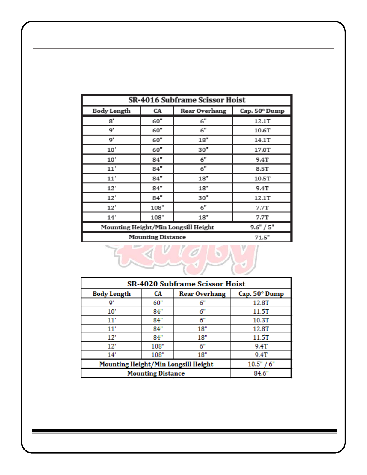
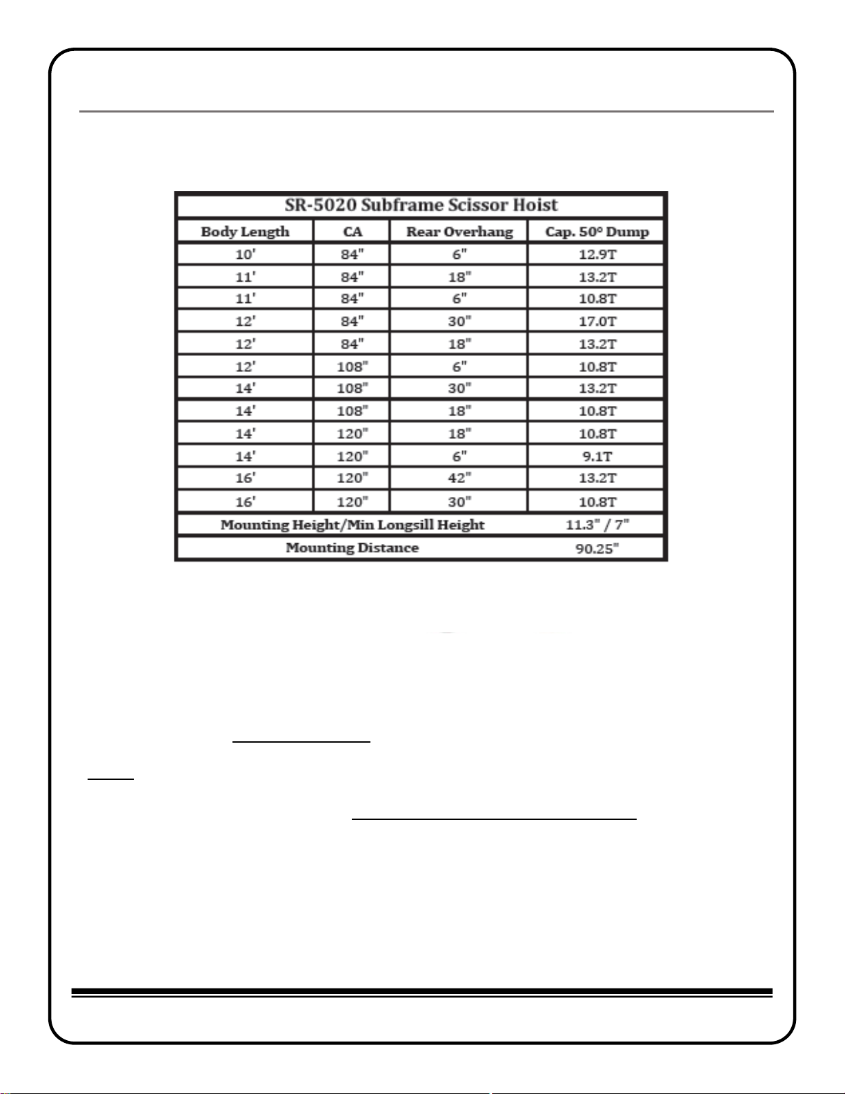
Capacity Chart..................................................................................................................................................................... 2
Torque Values Chart ....................................................................................................................................................... 4
Body Prop Application Chart........................................................................................................................................ 4
Hydraulic System............................................................................................................................................................... 5
Assembly & Installation.....................................................................................................................................6
Body Prop Installation.................................................................................................................................................... 6
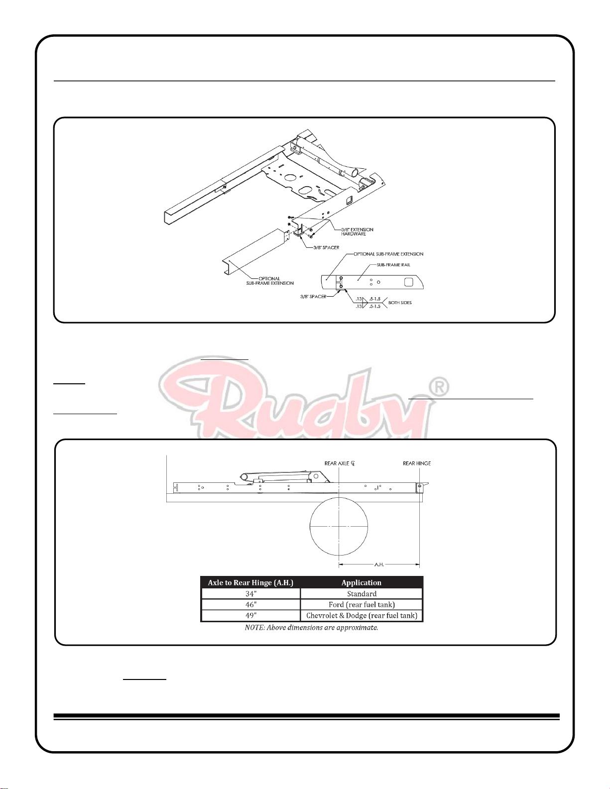
Hoist & Sub-frame Assembly ....................................................................................................................................... 7
Hoist & Sub-frame Installation.................................................................................................................................... 8
45° Application Sub-frame Modification...............................................................................................................14
Decal Locations.................................................................................................................................................................15
Operation.............................................................................................................................................................16
Body Prop Operation......................................................................................................................................................16
Maintenance........................................................................................................................................................16
Diagrams..............................................................................................................................................................17

Rugby Manufacturing 1841488C | 13-Jul-20 Page 1
Rugby Manufacturing SR-Series Hoist Manual
How to Use This Manual
This manual provides guidelines, and instructions for correctly assembling, operating and
maintaining your Rugby Manufacturing product. Any and all people that own and operate this prod-
uct must read and fully understand each section in this manual.
Labels
Throughout this manual, the three following types of labels will be used: danger, warning, and
caution. It is imperative that all labels are obeyed, for the safety of the operator
Indicates a hazardous situation which, if not avoided, will result in
death or serious injury
Indicates a hazardous situation which, if not avoided, could result in
death or serious injury.
Indicates a hazardous situation which, if not avoided, could result in
minor or moderate injury.
Reference Information
Serial Number
This information is required for any warranty or service inquiries, and should be recorded on the front
page of this manual for easy reference.
Figure 1
The serial number plate is located on the rear spacer plate of the hoist (Figure 1).

Rugby Manufacturing 1841488C | 13-Jul-20 Page 2
Rugby Manufacturing SR-Series Hoist Manual
Figure 2A
Figure 2B
Capacity Charts

Rugby Manufacturing 1841488C | 13-Jul-20 Page 3
Rugby Manufacturing SR-Series Hoist Manual
Figure 2C
The Capacity Charts (Figure 2A, 2B, & 2C) are to be used as a reference when determining capacity
based on overhang.
NOTE: Approximately 10% additional capacity can be attained on an SR-4016 application if sub-
frame and hoist are installed at 45°. A sub-frame modification kit can be ordered from Rugby Mfg if
this installation is desired. Refer to the 45° Application Sub-frame Modification section of this
manual for additional information and instructions.

Rugby Manufacturing 1841488C | 13-Jul-20 Page 4
Rugby Manufacturing SR-Series Hoist Manual
Torque Values Chart
Figure 3
Figure 4
The Torque Values Chart (Figure 3) is to be used as a guide during installation.
Body Prop Application Chart
The Body Prop Application Chart (Figure 4) is to be used along with the below instructions to
determine whether a second body prop will be necessary for your application.
1. Pick the X Value that is equal to or immediately larger than the X value for your application.

Rugby Manufacturing 1841488C | 13-Jul-20 Page 5
Rugby Manufacturing SR-Series Hoist Manual
Bouncing or jerking of the hoist is to be avoided as it may result in
component failure, injury or death.
Do not raise or drive a raised body against another object. Doing so
could result in equipment or property damage, injury or death.
Connecting the hoist to a hydraulic system with more pressure (psi) or
flow (gpm) than is recommended can lead to damage, serious injury,
or death
Do not operate the hoist until bystanders are free & clear of the
hoist and body.
Overloading of a truck can cause truck component damage, injury or
death. Never exceed the gross vehicle weight (GVW) or gross axle
weight (GAW) rating of your vehicle.
Unlatch tailgate prior to elevating a loaded dump body as excessive
forces on the rear of the dump body may result in component failure.
2. The weights shown below each “X” value reflect the maximum empty body weights that can
be supported by the integrated body prop included with the SR series hoists. If your body
weighs more than the amount listed, an additional body prop will need to be installed.
Contact Rugby Manufacturing to order an additional body prop.
General Safety
Hydraulic System
The hydraulic system supplied with an SR-series hoist manufactured by Rugby Manufacturing Co. is
made up of components (pump, valves, reservoir, hoses, cylinder, etc.) that are designed to be com-
patible with each other. Several different types of pump and hydraulic components are available to
power the SR-series hoists. Refer to the pump and hydraulic component Installation and Operation
Manual for more information.
If hydraulic components are substituted, it is the installer’s responsibility to be sure they are compatible
with the components supplied by Rugby Manufacturing Co. Incompatible hydraulic components may
cause failure of the hoist which in turn could damage the truck, damage other property, and cause human
injury or death. All Rugby Manufacturing Company’s liability and warranty for a given hoist will be voided
if it is determined by Rugby Manufacturing Co. that substituted hydraulic components were used that
were incompatible with those supplied by Rugby Manufacturing Co.

Rugby Manufacturing 1841488C | 13-Jul-20 Page 6
Rugby Manufacturing SR-Series Hoist Manual
Assembly & Installation
Body Prop Installation
A body prop & required hardware is supplied with every SR-series hoist package. To determine
whether a second body prop is necessary for your application, refer to the Body Prop Application
Chart. For instructions on how to raise and lower the body prop, refer to the Operation section of
this manual.
The body prop is only to be used to prop an unloaded body. Serious
injury or death can occur if the body prop is misused.
Figure 5
1. Insert the body prop into the body prop bracket. (Figure 5).
2. Fasten the body prop to the body prop bracket using the supplied hardware.
3. Lower the body prop to the down position & align with slot until the body prop rests
against the top of the holder.

Rugby Manufacturing 1841488C | 13-Jul-20 Page 7
Rugby Manufacturing SR-Series Hoist Manual
Hoist & Sub-frame Assembly
A full breakdown of the hoist & sub-frame components can be found in the Diagrams section of this
manual.
1. Slide the saddle shaft into the lower tube of the hoist so that approximately 4 inches extend past
the tube on each side. (Figure 6.)
2. Position the hoist into the subframe by aligning each end of the saddle shaft into the subframe
brackets.
3. Secure the saddle shaft to the sub-frame with the provided hardware as shown in Figure 7. Refer
to Figure 3 for torque guidelines.
Figure 6
Figure 7

Rugby Manufacturing 1841488C | 13-Jul-20 Page 8
Rugby Manufacturing SR-Series Hoist Manual
Hoist & Sub-frame Assembly cont.
4. Position a provided 3/8” spacer under each sub-frame rail as far forward as possible. Secure to
rail by welding as shown. (Figure 8)
NOTE: Optional 12” or 24” bolt-on sub-frame extensions can be installed to convert the 9’ subframe to a
10’ or 11’ as required. For optional 45° dump angle applications, refer to the 45° Application Sub-frame
Modification section.
Hoist & Sub-frame Installation
1. Position the assembled hoist & sub-frame onto the truck frame using the application chart
shown in (Figure 9).
Figure 8
Figure 9

Rugby Manufacturing 1841488C | 13-Jul-20 Page 9
Rugby Manufacturing SR-Series Hoist Manual
Hoist & Sub-frame Installation cont.
2. Locate the ideal mounting angle location along the chassis frame while keeping within the
guidelines shown in (Figure 10). Ensure that the weld from the subframe to the mounting
angle will be positioned directly below the saddle tube.
NOTE: Optional 10ga rivet spacers may be positioned under the mounting angle and the rear hinge angle
to clear rivets on the truck frame.
Welding, oxy-fuel cutting, or grinding sparks can cause fuel to ignite
which in turn can lead to injury or death. Always take adequate steps to
avoid ignition of fuel from fuel tanks when welding, grinding, or oxy-
fuel cutting during equipment installation.
Heat from the truck’s exhaust system can cause hydraulic component
failure and may lead to a fire which could cause injury or death. Always
install equipment in locations where heat from the exhaust system will
not damage any hydraulic components.
Figure 10

Hoist & Sub-frame Installation cont.
Rugby Manufacturing 1841488C | 13-Jul-20 Page 10
101010P1010101101010
Rugby Manufacturing SR-Series Hoist Manual
3. Secure each mounting angle to the truck frame by drilling two 17/32” diameter holes and bolting
the mounting angles to the truck frame using two 1/2” GR8 bolts and nuts (Figure 11).
4. Weld each mounting angle to the sub-frame rail, keeping within the guidelines shown
in (Figure 11). Do not weld the mounting angles to the chassis frame.
5. Next, weld the rear hinge angle to the chassis frame as shown in Figure 12.
6. Cut any excess frame off behind the sub-frame rear hinge.
Figure 11
Figure 12

Hoist & Sub-frame Installation cont.
Rugby Manufacturing 1841488C | 13-Jul-20 Page 11
101010P1010101101010
Rugby Manufacturing SR-Series Hoist Manual
7. Slide a lock collar onto each lifting shaft, and then slide the shafts into each end of the upper
hoist tube (Figure 13).
8. Install a body guide plate onto each sub-frame rail using one of the sets of bolt holes provided.
Fasten guides using the supplied hardware.
Figure 13

Hoist & Sub-frame Installation cont.
Rugby Manufacturing 1841488C | 13-Jul-20 Page 12
101010P1010101101010
Rugby Manufacturing SR-Series Hoist Manual
9. Position the rear hinge brackets against the bottom side of the long beams. Once in position,
weld the rear hinge brackets to the body long beams as shown in Figure 14.
10. Slide each lift bracket against the inside of the long beam channel. Then weld the lift bracket to
the outside of the long beam (Figure 14).
11. With the lift bracket secured, slide the lock collars against the hoist lifting tube and lock them in
place by tightening the 3/8” set screw.
Figure 14

Hoist & Sub-frame Installation cont.
Rugby Manufacturing 1841488C | 13-Jul-20 Page 13
101010P1010101101010
Rugby Manufacturing SR-Series Hoist Manual
Figure 15
12. Install and grease the fittings as shown in Figure 15.

Rugby Manufacturing 1841488C | 13-Jul-20 Page 14
101010P1010101101010
Rugby Manufacturing SR-Series Hoist Manual
45° Application Sub-frame Modification
This section outlines the steps required to convert the standard SR-4016 50° application sub-frame
into a 45° application sub-frame. Additional modifications to cross-members or other platform/dump
body components may be required.
1. Contact Rugby Mfg to order the required kit for this modification: 1867517 - EXTENSION, 45
DEGREE SF MOD PCBLK.
2. Locate the Ø 1/8” x 1-1/2” slot found on the left and right sub-frame channels.
3. Cut through the left and right sub-frame channels at the cut centerline as shown in Figure 16.
4. Insert an extension between the front and rear portion of the sub-frame rails and install the
1/2” hardware.
5. Cut off the excess from the front of the sub-frame channels as applicable to return the sub-frame
channel to the original 102” overall dimension.
6. The sub-frame is now set up for a 45° dump angle. Continue installing the hoist and sub-frame
per the Hoist & Sub-frame Installation section of this manual.
Figure 16

Decal Locations
Rugby Manufacturing 1841488C | 13-Jul-20 Page 15
101010P1010101101010
Rugby Manufacturing SR-Series Hoist Manual
Two Body Prop Operation decals are supplied with each SR-series hoist. These decals must be
positioned as shown in (Figure 17). The chosen decal location should be free of any viewing ob-
structions.
Two Danger decals are supplied with each SR-series hoist. These decals must be positioned as shown in
(Figure 18) on both the left and right hand sides of the truck. The chosen decal locations should be free
of any viewing obstructions.
To obtain replacement decals, contact your Rugby dealer or Rugby Manufacturing Co.
Missing or damaged decals can lead to accidents which may cause
serious injury or death. If any decals are missing or damaged, they must
be replaced immediately.
Figure 17
Figure 18

Operation
Rugby Manufacturing 1841488C | 13-Jul-20 Page 16
101010P1010101101010
Rugby Manufacturing SR-Series Hoist Manual
Body Prop Operation
1. Raise unloaded body to sufficient height and shut off all power.
2. While positioning yourself as far as possible from underneath the truck, grasp prop from
latched position.
3. Rotate prop upwards to vertical position.
4. Push down until the prop locks in vertical position.
5. To lower the body prop for operation of truck, “reverse” the above procedure.
The body prop is only to be used to prop an unloaded body. Seri-ous
injury or death can occur if the body prop is misused.
Maintenance
Grease all hoist and rear hinge grease fittings every 100 cycles or every two months. Some grease
fittings are in hard to find locations - Refer to Figure 15 for all grease fitting locations.
Check hardware regularly and retighten as needed. Refer to Figure 3 for torque guidelines.
Check hydraulic components regularly for any leaks or signs of wear. Replace damaged or leaking
components as needed. Refer to the pump or hydraulic components installation and operation
manual for more service information.

Diagrams
Rugby Manufacturing 1841488C | 13-Jul-20 Page 17
101010P1010101101010
Rugby Manufacturing SR-Series Hoist Manual
ITEM
PART #
DESCRIPTION
QTY
1
1822323
FRAME, SR-4016 PCBLK HOIST
1
2
1831466
CYLINDER, 5.50 X 16
1
3
1822321
SUBRRAME, 09’ SR-4016 PCBLK
1
4
1839407
PROP, BODY PCBLK
1
5
1653917
PIN, 1/8” X 1” PLATED COTTER
1
6
1857937
PIN, ½” X 2.75” ZP CLEVIS
1
7
1822289
BRACKET, SR LIFT
2
8
1653845
SET SCREW, 3/8-16 X 5/8 SQR HD, BLK
2
9
1656191
LOCK COLLAR, 2.25
2
10
1620051
HHC SCREW, ½-13 X 2.5, GR. 8, PLT
2
11
1642984
NUT, 1/2-13 NYLOCK - NE, GR8 STL
4
12
1653838
HHC SCREW, 5/8-11 X 4 , GR8, PLT
1
13
1643070
NUT, 5/8-11 NYLOCK - NE, GR. 5 STL
1
14
1520370
FITTING, 1/4-28 THREAD FORMING GREASE
7
15
1581116
SERIAL NO. PLATE, POLY W/MASK
1
16
1822332
SHAFT, SADDLE PIVOT
1
17
1653835
HHC SCREW, 1/2-13 X 4 GR5 PLT
2
18
1822291
PLATE, SUBFRAME BODY GUIDE
2
19
1577459
BOLT, 1/2-13 X 1-1/2 FLG GR5
4
20
1576016
NUT, 1/2-13 FLANGE, GR5 STL, PLT
4
21
1535863/
1851733
KIT, SUB-FRAME EXTENSION (OPTIONAL)
1
ITEM
PART #
DESCRIPTION
QTY
1
2117068
FRAME, SR-4020 PCBLK HOIST
1
2
1315043
CYLINDER, 5.5 X 20 HR-550
1
3
2193587
SUBFRAME, 09" SR-4020
1
4
1839407
PROP, BODY PCBLK
1
5
1653917
PIN, 1/8" X 1" COTTER
1
6
1857937
PIN, 1/2" X 2.75" ZP CLEVIS
1
7
1822289
BRACKET, SR LIFT
2
8
1653845
SET SCREW, 3/8-16 X 5/8 SQR HD BLK
2
9
1656191
COLLAR, 2.25 LOCK
2
10
1653835
SCREW, 1/2-13 X 4 HHC GR5 PLT
2
11
1642984
NUT, 1/2-13 NYLOCK - NE GR8 STL
4
12
1653838
SCREW, 5/8-11 X 4 HHC GR8 PLT
1
13
1643070
NUT, 5/8-11 NYLOCK - NE, GR. 5 STL
1
14
1520370
FITTING, 1/4-28 THREAD FORMING GREASE
7
15
1581116
SERIAL NO. PLATE, POLY W/MASK
1
16
1898583
SHAFT, SADDLE PIVOT
1
17
1653835
SCREW, 1/2-13 X 4 HHC GR5 PLT
2
18
1831125
PLATE, BOLT-ON PCBLK BODY GUIDE
2
19
1577459
BOLT, 1/2-13 X 1-1/2 FLG GR5
4
20
1576016
NUT, 1/2-13 FLANGE GR5 STL PLT
4
21
1535863/
1851733
KIT, SUB-FRAME EXTENSION (OPTIONAL)
1
SR-4016 Hoist & Sub-frame
SR-4020 Hoist & Sub-frame

Diagrams cont.
v
Rugby Manufacturing 1841488C | 13-Jul-20 Page 18
101010P1010101101010
Rugby Manufacturing SR-Series Hoist Manual
ITEM
PART #
DESCRIPTION
QTY
1
1844062
FRAME, SR-5020 PCBLK HOIST
1
2
1621268
CYLINDER, 6 X 20, 2.5 ROD, 2.0 NECK
1
3
1653838
HHC SCREW, 5/8-11 X 4, GR8, PLT
1
4
1643070
NUT, 5/8-11 NYLOCK - NE, GR. 5 STL
1
5
1520370
FITTING, 1/4-28 THREAD FORMING GREASE
7
6
1581116
SERIAL NO. PLATE, POLY W/MASK
1
7
1844096
SHAFT, 5020 CYL PINNING
1
8
1653921
COTTER PIN, 5/16" X 3-1/2" PLATED
2
9
1844097
SUBFRAME, 09' SR-5020 PCBLK
1
10
1822332
SHAFT, SADDLE PIVOT
1
11
1653835
HHC SCREW, 1/2-13 X 4 GR5 PLT
2
12
1642984
NUT, 1/2-13 NYLOCK - NE, GR8 STL
2
13
1839407
PROP, BODY PCBLK
1
14
1857937
PIN, 1/2" X 2.75" ZP CLEVIS
1
15
1653917
PIN, 1/8" X 1" PLATED COTTER
1
16
1822289
BRACKET, SR LIFT
2
17
1656191
LOCK COLLAR, 2.25
2
18
1653845
SET SCREW, 3/8-16 X 5/8 SQR HD, BLK
2
19
1831125
PLATE, BOLT-ON PCBLK BODY GUIDE
2
20
1577459
BOLT, 1/2-13 X 1-1/2 FLG GR5
4
21
1576016
NUT, 1/2-13 FLANGE, GR5 STL, PLT
4
22
1535863/
1851733
KIT, SUB-FRAME EXTENSION (OPTIONAL)
1
SR-5020 Hoist & Sub-frame
This manual suits for next models
3
Table of contents
Popular Power Tools manuals by other brands

Tone
Tone Power Digitorqon PDX-302N instruction manual

BLACK DECKER
BLACK DECKER MT218 Original instructions

PROCRAFT
PROCRAFT PMM2000 Translation of the original operating manual

FLORABEST
FLORABEST FBK 4 A1 translation of original operation manual

Worx Nitro
Worx Nitro WG330E.X Safety and operating manual

AL-KO
AL-KO MT 36 LI manual