5
WWW.RUNPOTEC.COM
4 DEUTSCH DEUTSCH 5
BESTIMMUNGSGEMÄSSE VERWENDUNG
EINFÜHRUNG
Die Firma RUNPOTEC bedankt sich für den Kauf der tragbaren
Spillwinde CW 800 E. Diese Gebrauchsanleitung informiert Sie über die si-
chere Nutzung. Lesen Sie die Gebrauchsanleitung vor Inbetriebnahme
sorgfältig durch. Wenn Sie Fragen zu Inbetriebnahme, Montage, Sicherheit
und Anwendung oder Störungen haben, stehen Ihnen Ihr Vertragshändler
oder die Firma RUNPOTEC telefonisch oder per E-Mail zur Verfügung. Unsere
Kontaktdaten finden Sie auf Seite 2.
SICHERHEITSINFORMATIONEN
Die Spillwinde darf nur von Personen betrieben werden, die mit dem
Umgang vertraut gemacht wurden.
Betriebssicheren Zustand der Spillwinde jeweils vor Benutzung prüfen.
Die Spillwinde darf nicht benutzt werden, wenn Beschädigungen am
Gerät festgestellt werden.
Das Zugseil, sowie alle damit verbundenen Teile müssen die in den
technischen Daten aufgeführten Anforderungen erfüllen und dürfen
keine Beschädigungen aufweisen.
Das Bedienungspersonal muss persönliche Schutzausrüstung gemäß
Baustellenevaluierung tragen.
Vor Arbeitsbeginn vorhandene Hindernisse im Arbeitsbereich entfernen.
Die Spillwinde ist so zu befestigen, dass die Zugkräfte gefahrlos in den
Boden oder in die Anlage eingeleitet werden.
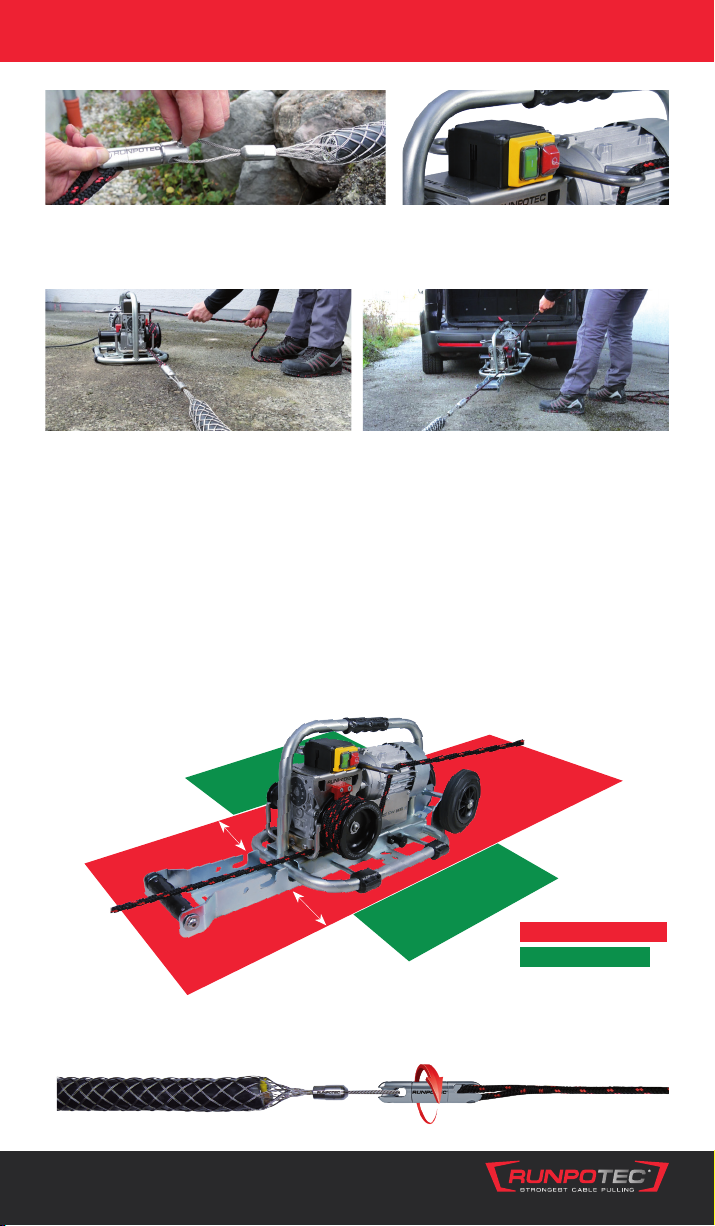
Die bedienende Person steht mit ausreichendem Sicherheitsabstand
neben der Spillwinde und zieht das Zugseil mit geringem Kraftaufwand
im 90°-Winkel zur Zugrichtung über die Sicherheitsseilführung.
Während des Zugvorgangs nicht in den Spill und das umwickelte bzw.
ein- und auslaufende Seil fassen.
Alle Abbildungen sind Symbolfotos. Änderungen und Druckfehler vorbehalten.
Die RUNPOTEC Spillwinde ist NUR für waagrechten Kabelzug bestimmt.
Das Transportieren von Personen ist verboten!
Jede nicht beschriebene Verwendung stellt eine bestimmungswidrige
Verwendung dar.
Die Nutzungsdauer von 4 Jahren kann bei entsprechender Sorgfalt um
ein vielfaches überschritten werden.
Durch bestimmungswidrige Verwendung oder Veränderung der
Maschine entfallen die gesetzliche Gewährleistungspflicht des
Maschinenherstellers und die Produkthaftung.
RUNPOTEC empfiehlt aufgrund des idealen Umschlingungsfaktors das
Zugseil Polyester mit Ø 10 mm.