Ryobi RBV254 User manual

ORIGINAL INSTRUCTIONS
Blower/Vacuum
RBV254

Important!
It is essential that you read the instructions in this manual before assembling,
operating and maintaining the product.
Subject to technical modification.

1
1
10 11 12
9
18
13
14
15
16
19
17
20
2345
6
7
21
22
23
8
Fig. 1
Fig. 2

2
24
25
1
2
26
24 27
25
1
2
28
29
5
Fig. 3
Fig. 5
Fig. 4
Fig. 6
Fig. 7

3
STOP
10
11
18
15
19
RUN
HALF
FULL
RUN
HALF
FULL
RUN
HALF
FULL
33
35
34
22
1
2
26
3
1
2
4
1
30
31
32
27
Fig. 11
Fig. 12
Fig. 9
Fig. 8
Fig. 10

4
3
9
11
1
2
3 3
Fig. 14 Fig. 16
Fig. 13
Fig. 15

5
Safety, performance, and dependability have been given
top priority in the design of your blower/vacuum.
INTENDED USE
The product is only intended for use outdoors in a well
ventilated area.
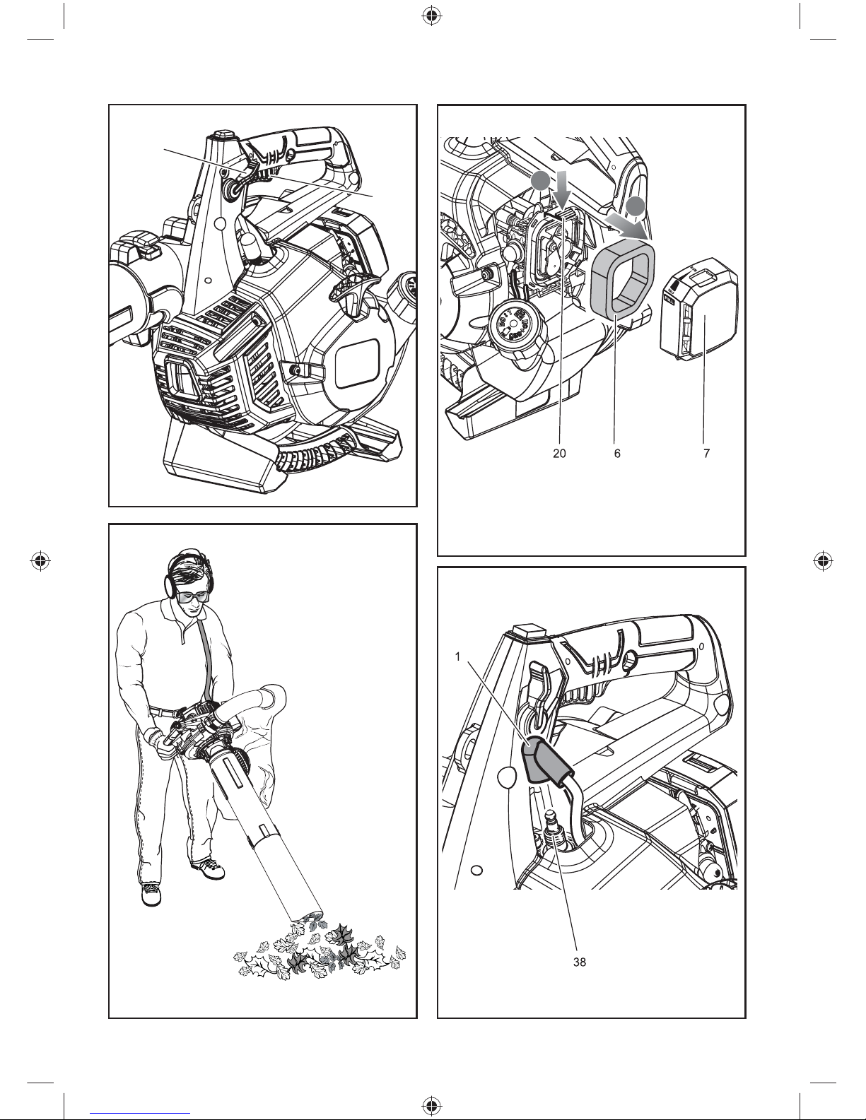
The product is intended for blowing light debris including
leaves, grass and other garden refuse. It is intended to
vacuum and mulch light debris as above and collect in the
debris bag. It is not designed to suck or vacuum water or
other liquids.
WARNING
When using the product, the safety rules must be
followed. For your own safety and that of bystanders,
please read these instructions before operating the
product. Please keep the instruction safe for later use.
WARNING
Never allow children or people with reduced physical,
sensory or mental capabilities to operate, clean or
maintain the product. Local regulations may restrict the
age of the operator.
Tragic accidents can occur if the operator is not alert to
the presence of children. Children are often attracted to the
product and the blowing/vacuuming activity. Never assume
that children will remain where you last saw them.
Keep children out of the work area and under the watchful
care of a responsible adult other than the operator, be alert
and turn the product off if a child enters the area.
GENERAL SAFETY WARNINGS
■Some regions have regulations that restrict the use of
the product to some operations. Check with your local
authority for advice. Read all instructions.
■Do not allow children or untrained individuals to use this
unit.
■Ensure before each use that all controls and safety
devices function correctly. Do not use the tool if the “off”
switch does not stop the engine.
■Never start or run the engine in a closed or poorly
ventilated area; breathing exhaust fumes can kill.
■Clear the work area before each use. Remove all
objects such as rocks, broken glass, nails, wire, or
string which can be blown a considerable distance by
high velocity air.
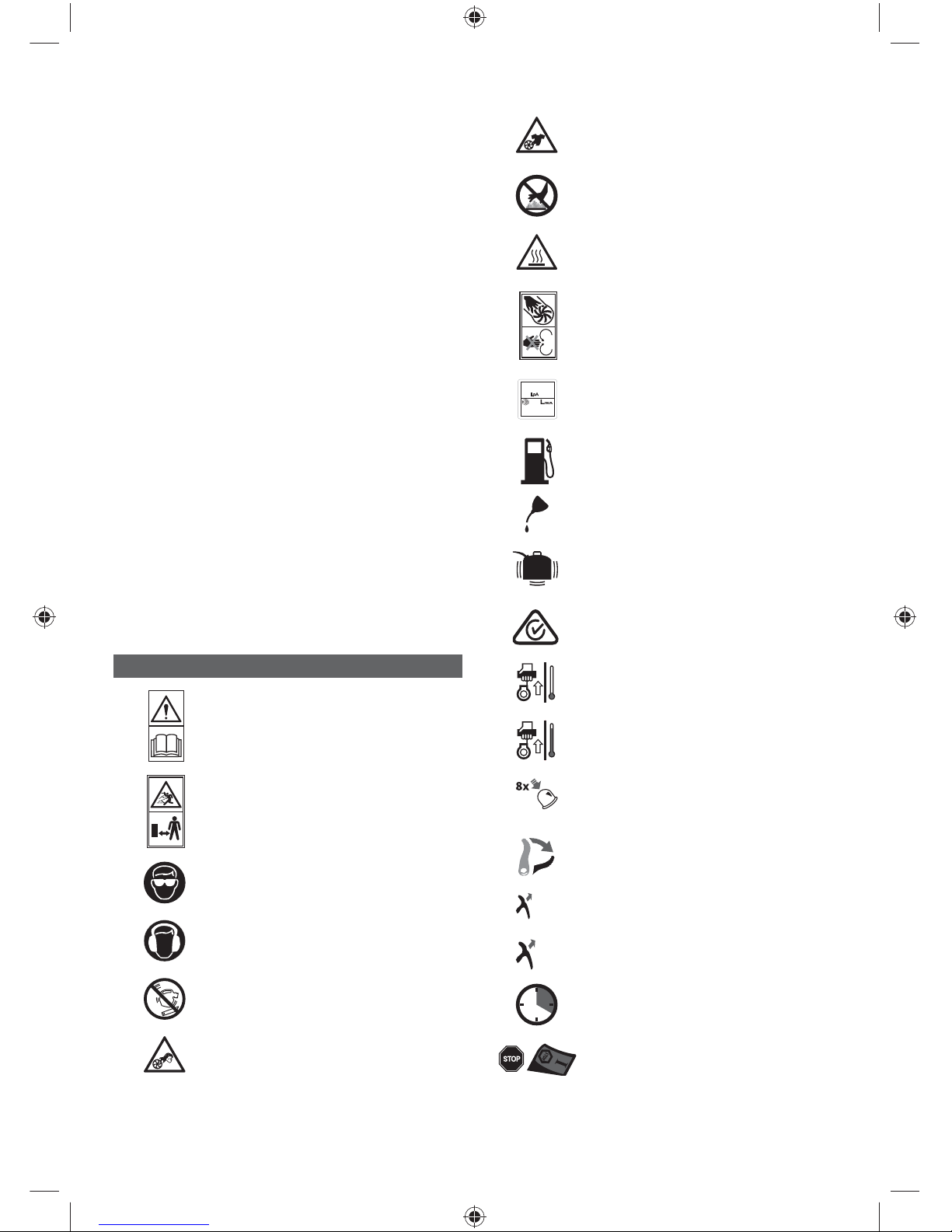
■Wear full eye and hearing protection while operating
the product. This machine is extremely noisy and
permanent hearing may result if precautions to limit our
exposure, reduce noise and wear hearing protection
are not strictly adhered to.
■Wear heavy long trousers, boots, and gloves. Do not
wear loose fitting clothing, short trousers, jewellery of
any kind, or use with bare feet.
■Secure long hair so it is above shoulder level to prevent
entanglement in moving parts.
■Beware of thrown objects; keep all bystanders, children,
and pets at least 15 m away from work area.
■Operate the machine only at reasonable hours – not
early in the morning or late at night when people might
be disturbed.
■Use rakes and brooms to loosen debris before blowing/
vacuuming.
■Never operate the product in an explosive atmosphere.
■Do not use this machine when you are tired, ill, or under
the influence of alcohol, drugs, or medication.
■Do not operate in poor lighting. The operator requires a
clear view of the work area to identify potential hazards.
■Use of hearing protection reduces the ability to hear
warnings (shouts or alarms). The operator must pay
extra attention to what is going on in the working area.
■Only use enough throttle (power) to complete the task,
this will reduce the potential for injury caused by noise
and vibration.
■Operating similar tools nearby increases both the risk
of hearing injury and the potential for other persons to
enter your working area.
■Keep firm footing and balance. Do not overreach.
Overreaching can result in loss of balance or exposure
to hot surfaces.
■Keep all parts of your body away from any moving part.
Rotating impeller blades can cause severe injury. Stop
the engine and ensure impeller blades have stopped
rotating before opening the vacuum door, installing/
changing tubes, opening or removing debris bag.
■Do not touch the area around the silencer or engine of
the unit, these parts get very hot during operation.
■Inspect the machine before each use. Check for loose
fasteners, fuel leaks, etc. Make sure all guards, and
handles are properly and securely attached. Replace
any damaged parts before use.
■Never run the unit without the proper equipment
attached. When used as a blower, always install the
blower tubes and close the door. When used as a
vacuum, always install the vacuum tubes and vacuum
bag.
■Do not modify the machine in any way or use parts
and accessories which are not recommended by the
manufacturer.
WARNING
If the machine is dropped, suffers heavy impact or
begins to vibrate abnormally, immediately stop the
machine and inspect for damage or identify the cause of
the vibration. Any damage should be properly repaired
or replaced by an authorised service centre.
■Stop the engine and allow it to cool before refuelling,
storing or transporting the machine.
■For refuelling and fuel mixing, chose an area away from
sources of ignition (sparks, flames etc.), flammable
materials, and which is well ventilated.
■Do not smoke when mixing fuel or filling fuel tank.
■Mix and store fuel in a container approved for fuel.

6
Keep an appropriate type of fire extinguisher nearby for
dealing with fuel fires.
■Remember to securely refit the fuel tank filler cap
before starting the engine.
■Wipe up any fuel spillage. Move 9 m away from
refuelling site before starting engine.
■It has been reported that vibrations from hand-held
tools may contribute to a condition called Raynaud’s
Syndrome in certain individuals. Symptoms may
include tingling, numbness and blanching of the fingers,
usually apparent upon exposure to cold. Hereditary
factors, exposure to cold and dampness, diet, smoking
and work practices are all thought to contribute to
the development of the these symptoms. There are
measures that can be taken by the operator to possibly
reduce the effects of vibration:
●Keep your body warm in cold weather. When
operating the unit wear gloves to keep the hands
and wrists warm. It is reported that cold weather is
a major factor contributing to Raynaud’s Syndrome.
●After each period of operation, exercise to increase
blood circulation.
●Take frequent work breaks. Limit the amount of
exposure per day.
If you experience any of the symptoms of this condition,
immediately discontinue use and see your doctor about
these symptoms.
■To reduce the risk of injury associated with contacting
rotating parts, always stop the engine, remove the
spark plug wire and make sure all moving parts have
been come to a stop before:
●cleaning or clearing a blockage
●leaving the product unattended
●install or removing attachments
●checking, maintenance or working on the machine
WARNING
Injuries may be caused, or aggravated, by prolonged
use of a tool. When using any tool for prolonged
periods, ensure you take regular breaks.
WARNING
Your Blower / Vacuum machine may be supplied with
a harness. Carefully adjust the harness to comfortably
help to support the weight of the machine and hang at
your right hand side.
WARNING
Identify the Quick Release mechanism and practice
using it before you start using the machine. Its
correct use may prevent serious injury in the case of
an emergency. Never wear additional clothing over
the harness or otherwise restrict access to the quick
release mechanism.
BLOWER SAFETY WARNINGS
■Wear a face filter mask in dusty conditions to reduce
the risk of injury associated with the inhalation of dust.
■Do not point the blower nozzle in the direction of people
or pets.
■Never place objects inside the blower tubes.
■Do not operate the machine near open windows etc..
■Slightly dampen surfaces in dusty conditions.
■Use the full blower nozzle extension so the air stream
can work close to the ground.
■Do not place blower on top of or near loose debris.
Debris may be sucked into intake vent resulting in
possible damage to the unit.
VACUUM SAFETY WARNINGS
■Do not operate vacuum without vacuum bag assembly
installed; flying debris could cause serious injury. Make
sure the vacuum bag is completely zipped closed
before operating.
■Move the vacuum from side to side along outer edge of
debris. To avoid clogging, do not place the vacuum tube
directly into the debris pile.
■Hold the engine higher than the inlet end of the vacuum
tube.
■Always point vacuum tube downhill when working on
a hillside.
■To avoid serious injury to the operator or damage to
the unit, do not try to vacuum up rocks, broken glass,
bottles, or other similar objects.
■Avoid situations that could cause fire in the vacuum
bag. Do not operate near an open flame. Do not
vacuum warm ash from fireplaces, barbecue pits etc.
Do not vacuum discarded cigars or cigarettes unless
the cinders are completely cool.
RESIDUAL RISK
Even when the product is used as prescribed, it is still
impossible to completely eliminate certain residual risk
factors. The following hazards may arise in use and the
operator should pay special attention to avoid the following:
■Injury caused by vibration. Always use the right tool for
the job, use designated handles and restrict working
time and exposure.
■Exposure to noise can cause hearing injury. Wear ear
protection and limit exposure.
■Injury from flying objects from the blow tube airflow or
vacuum exhaust if the bag is not fitted or damaged.
DESCRIPTION
See pages 1-4.
PARTS
1. Lower vacuum tube
2. Upper vacuum tube
3. Lock ring
4. Main housing
5. Vacuum bag adaptor

7
6. Leaf bag
7. Vacuum tube screw
8. Leaf nozzle
9. Throttle lock
10. Stop switch
11. Throttle trigger
12. Upper handle
13. Spark plug boot
14. Muffler
15. Starter grip and rope
16. Vacuum handle
17. Fuel cap
18. Choke lever
19. Primer bulb
20. Air filter base tab
21. Vacuum inlet door
22. Sweeper nozzle
23. Upper blower tube
24. Main housing outlet
25. Raised locking tab
26. Locking tab
27. Raised tab
28. Door tab
29. Vacuum door hinge
30. Screw
31. Unlock
32. Lock
33. Full choke
34. Half choke
35. Run position
36. Air filter
37. Air filter cover
38. Spark plug
SYMBOLS ON THE PRODUCT
Read this safety and operating
instructions in this booklet and keep it
in a safe place for future reference
Beware of thrown or flying objects.
Keep all bystanders, especially
children and pets, at least 15 m away
from the operating area
Wear eye protection
Wear ear protection
Do not run unit without tubes in place.
Risk of long hair being drawn into air
inlet.
Risk of loose clothing being drawn into
air intake
To reduce the risk of injury or damage,
avoid contact with any hot surface
Warning! Hot surface
Rotating fans. Keep hands and feet
out of openings while the product is
running
AT IDLE
89 dB
110 dB
Guaranteed sound pressure and sound
power level
Use unleaded gasoline intended for
motor vehicle use with an octane rating
of 91 or higher.
Use 2-stroke oil for air cooled engines.
Mix the fuel mix thoroughly and also
each time before refuelling
Regulatory Compliance Mark (RCM).
This product meets applicable
regulatory requirements
Cold start
Warm start
PRIME - press the primer bulb 8 times
slowly
Lock the throttle lever
(
6X Max
)
Pull the starter grip until the engine
starts (6 max)
(
4X Max
)
Pull the starter grip until the engine
attempts to start (4 max)
Wait 20 seconds
To stop the unit: Place the engine
switch to the “STOP” position
The following signal words and meanings are intended to
explain the levels of risk associated with the product:

8
DANGER
Indicates an imminently hazardous
situation, which, if not avoided, will
result in death or serious injury.
WARNING
Indicates a potentially hazardous
situation, which, if not avoided, could
result in death or serious injury.
CAUTION
Indicates a potentially hazardous
situation, which, if not avoided, may
result in minor or moderate injury.
CAUTION
(Without safety alert symbol)
Indicates a situation that may result
in property damage.
PRODUCT SPECIFICATIONS
Engine displacement 25.4 cc
Air velocity 342 km/h
Air volume 13 m
3/min
Weight 4.1 kg
Rated power 0.80 kW
Engine speed (Max.) 10,000/min
Engine speed (Idle) 3,400 ~ 3,800/min
Vibration value at handle according to EN
15503:2009+A1:2013 Annex B:
Blower mode (Upper handle)
Racing: 14.6 m/s
2
Idling: 5.4 m/s
2
Equivalent vibration total
value:
13.7 m/s
2
Vacuum mode (Upper handle/Vacuum handle)
Racing 13.1 / 14.6 m/s
2
Idling 5.0 / 5.2 m/s
2
Equivalent vibration total
value
12.3/13.7 m/s
2
Uncertainty K (Vibration) 1.5 m/
s2
Sound power level according to EN 15503:2009+A1:2013
Annex A (Blower / vacuum) :
Racing 107.3 / 104.7 dB(A)
Idling 91.7 / 89.9 dB(A)
Equivalent A-weight Sound
power level:
107.3 / 104.7 dB(A)
Uncertainty K (sound power
level)
3 dB
Sound pressure level at operator position according to EN
15503:2009+A1:2013 Annex A (Blower/Vacuum)
Racing 101.8 / 100.9 dB(A)
Idling 85.6 / 84.8 dB(A)
Equivalent A-weight
emission sound pressure
level
101.1 / 100.2 dB(A)
Uncertainty K (sound
pressure level)
3 dB
FEATURES
KNOW YOUR BLOWER/VACUUM
See figure 1-2.
The safe use of this product requires an understanding of
the information on the tool and in this operator’s manual as
well as a knowledge of the project you are attempting to do.
BLOWER TUBE AND SWEEPER NOZZLE (LEAF
NOZZLE)
The blower tubes and sweeper nozzle (or leaf nozzle) can be
assembled and installed on the main housing using no tools.
ENGINE
The blower has a powerful 25.4cc engine with sufficient power
to handle tough blowing and vacuuming jobs.
MULCHER
The blower is equipped with a metal mulching blade that
efficiently reduces leaves at a 10:1 ratio.
SWEEPER NOZZLE
The sweeper nozzle allows for more area to be covered
during blower operation.
LEAF NOZZLE
The leaf nozzle allows for a higher air speed during blower
operation.
THROTTLE LOCK
The throttle lock feature allows the user to operate the blower
without holding the throttle trigger. To slow the engine speed,
simply push the throttle lock forward.
THROTTLE TRIGGER
The blower can be operated at any speed between idle
and full throttle.
VACUUM/MULCHER
Converting the blower to a vacuum/mulcher is simple and
can be done using a straight screwdriver.
VACUUM BAG
The vacuum bag attaches to the main housing easily by
using the vacuum bag adaptor.
VACUUM HANDLE
This feature allows user to perform vacuuming duties
comfortably.

9
VACUUM TUBES
The vacuum tubes can be installed on the main housing
using a flat head screwdriver.
ASSEMBLY
PACKING LIST
Blower
Upper blower tube
Sweeper nozzle
Leaf nozzle
Upper and lower vacuum tubes
Vacuum tube screws (2)
Vacuum bag assembly
Vacuum bag adaptor
2-Cycle engine lubricant
Operator’s manual
NOTE: Read and remove all hang tags and store with your
Operator’s Manual.
UNPACKING
This product requires assembly.
■Carefully remove the product and any accessories from
the box. Make sure that all items listed in the packing
list are included.
WARNING
Do not use this product if any parts on the Packing
List are already assembled when you first open the
box. The parts on this list are not assembled by the
manufacturer and require customer installation. Use of
a product that may have been improperly assembled
could result in serious personal injury.
■Inspect the product carefully to make sure no breakage
or damage occurred during shipping.
■Do not discard the packing material until you have
carefully inspected and satisfactorily operated the
product.
■If any parts are damaged or missing, please call your
Ryobi service centre for assistance.
WARNING
If any parts are damaged or missing do not operate this
product until the parts are replaced. Use of this product
with damaged or missing parts could result in serious
personal injury.
WARNING
Do not attempt to modify this product or create
accessories not recommended for use with this
product. Any such alteration or modification is misuse
and could result in a hazardous condition leading to
possible serious personal injury.
WARNING
To prevent accidental starting that could cause serious
personal injury, always disconnect the engine spark
plug wire from the spark plug when assembling parts.
TOOLS NEEDED
The following tool (not included or drawn to scale) is needed
for assembly:
■Flat head screwdriver
ASSEMBLING AND DISASSEMBLING THE UPPER
BLOWER TUBE AND SWEEPER NOZZLE
See figure 3-4.
1. Align the raised locking tabs on the upper blower tube
to the slots on the main housing outlet. Slide together
and tighten securely by twisting. Check tightness after
initial run and retighten if needed..
2. Secure the sweeper nozzle and upper blower tube
together by aligning the raised locking tab on the upper
blower tube with the raised slot on the sweeper nozzle.
3. To disassemble, raise the locking tab with a flat head
screwdriver, rotate the tube and nozzle to unlock and
remove from the main housing outlet.
INSTALLING THE VACUUM BAG
See figure 5-6.
1. Remove the sweeper nozzle (or leaf nozzle) and upper
blower tube from the main housing by raising the
locking tab with a flat head screwdriver, twisting and
removing from the main housing outlet.
2. Unzip the vacuum bag and place the adaptor inside.
Push the vacuum bag adaptor through the opening
opposite the zipper. The wider end of the adaptor will
remain on the inside of the vacuum bag when installed
properly.
3. Align the raised tabs on the vacuum bag adaptor to the
slots on the main housing outlet; push the bag adaptor
onto the housing. Twist to lock into place.
4. Rotate the vacuum bag until the shoulder strap is
upright.
5. Make sure the vacuum bag is zipped and closed before
starting the unit.
To remove the vacuum bag:
1. Remove the vacuum bag adaptor by lifting the locking
tab.
2. Rotate counter-clockwise to unlock the adaptor and
remove.
INSTALLING THE VACUUM TUBES
See figure 7-9.
WARNING
Rotating impeller blades can cause severe injury.
Always stop the engine and ensure that the impeller
blades have stopped rotating before opening the
vacuum door or installing/changing tubes. Do not put
hands or any other object into the vacuum tubes that
are installed on the unit.

10
To install the vacuum tubes:
1. Secure the upper and lower vacuum tubes together by
aligning the raised tabs with the raised slots.
2. Tap tube assembly on ground until the screw holes
in lower tube are in the raised slot of the upper tube.
Secure with supplied screws.
3. Depress door tabs using a flat head screwdriver and
open vacuum inlet door.
4. Align the slots on the vacuum tube housing with the
tabs on the main housing.
5. Turn the vacuum tube housing clockwise to the locked
position and secure to the main housing.
To remove the vacuum tubes:
1. Using a screwdriver, depress the tab on the lock ring
to unlock.
2. Turn the upper vacuum tube housing counter-clockwise.
3. Remove the vacuum tube assembly from the main
housing.
4. Close the inlet cover door securely.
OPERATION
WARNING
Do not allow familiarity with tools to make you careless.
Remember that a careless fraction of a second is
sufficient to inflict serious injury.
WARNING
Always wear eye protection with side shields marked to
comply with standards, along with hearing protection.
Failure to do so could result in objects being thrown into
your eyes and other possible serious injuries.
NOTE: Before each use, inspect the entire product for
damaged, missing, or loose parts such as screws, nuts, bolts,
caps, etc. Tighten securely all fasteners and caps and do
not operate this product until all missing or damaged parts
are replaced. Please contact customer service or a qualified
service centre for assistance.
APPLICATIONS:
You may use this tool for the purposes listed below:
■Clear leaves and other debris from your lawn
■Keep decks and driveways free from leaves and pine
needles
■Vacuuming leaves form your lawn
FUELLING AND REFUELLING
MIXING THE FUEL
This product is powered by a 2-stroke engine and requires
premixing petrol and 2-stroke oil. The mixture should be at
a 50:1 ratio.
NOTE: We recommend you use Ryobi synthetic 2-stroke
lubricant. Only use a quality synthetic 2-stroke lubricant in
your blower to ensure top performance and engine longevity.
TO MIX THE FUEL:
■Pre-mix unleaded petrol and 2-stroke engine lubricant
in a clean container approved for petrol.
■This engine is certified to operate on unleaded petrol
intended for automotive use with an octane rating of 91
or higher.
■Do not use any type of pre-mixed petrol/lubricant from
fuel service stations; this includes the pre-mixed petrol/
lubricant intended for use in mopeds, motorcycles, etc.
■Avoid using Ethanol fuels or fuels containing Ethanol.
The use of Ethanol fuels may result in damage to your
engine.
■Use only synthetic 2-stroke lubricant. Do not use
automotive lubricant or 2-stroke outboard lubricant.
■Mix 2% synthetic 2-stroke lubricant into the petrol. This
is a 50:1 ratio.
■Mix the fuel thoroughly and also each time before
fuelling.
■Mix in small quantities. Do not mix quantities larger than
usable in a 30-day period. A synthetic 2-stroke lubricant
containing a fuel stabiliser is recommended.
1 Litre + 20 ml =
2 Litres + 40 ml =
3 Litres + 60 ml = 50:1 (2%)
4 Litres + 80 ml =
5 Litres + 100 ml =
FILLING THE TANK
WARNING
Petrol is extremely flammable and explosive. A fire or
explosion from petrol will burn you and others. Always
shut off engine before fuelling. Never add fuel to a
machine with a running or hot engine. Move at least
9 m from refuelling site before starting engine. Do not
smoke and stay away from open flames and sparks.
Failure to safely handle fuel could result in serious
personal injury.
1. Clean the surface around the fuel cap to prevent con-
tamination.
2. Loosen the fuel cap slowly by turning it counter-
clockwise.
3. Pour the fuel mixture carefully into the tank.
4. Clean and inspect the fuel cap gasket before replacing
the fuel cap.
5. Replace the fuel cap and tighten it by turning it clock-
wise.
6. Wipe spilled fuel from the product.
7. Move at least 30 ft. (9 m) away from refuelling area
before starting the product.
NOTE: It is normal for smoke to be emitted from a new
engine during first use.

11
WARNING
Check for fuel leaks. A leaking fuel cap is a fire hazard
and must be replaced immediately. If you find any
leaks, correct the problem before using the product.
Failure to do so could result in a fire that could cause
serious personal injury.
STARTING AND STOPPING
See figure 10-11.
To start a cold engine:
1. Set the blower on a flat, bare surface.
2. Slowly press the primer bulb 8 times.
NOTE: After the 8th press, fuel should be visible in the
primer bulb. If it is not, continue to press the primer until
you see fuel in the bulb.
3. Place the choke lever in the FULL CHOKE position.
4. Pull throttle lock back to lock the throttle wide open.
5. Pull the starter grip and rope sharply until engine at-
tempts to run. Do not pull the starter grip more than
four (4) times.
6. Set the choke lever in the HALF CHOKE position.
7. Pull the starter grip and rope until the engine runs. Do
not pull the starter grip more than six (6) times.
NOTE: If the engine does not start, return to the FULL
CHOKE position and repeat steps 3 through 6 again.
8. Allow the engine to run for 20 seconds, then place the
choke lever in the RUN position.
NOTE: In cooler environments, additional pulls of the
starter grip may be required with the choke lever in the
FULL CHOKE position.
To start a warm engine:
1. Place the choke lever in the RUN position.
2. Pull throttle lock back to lock the throttle wide open.
3. Pull the starter grip and rope until the engine runs.
NOTE: If the engine does not start, repeat steps 3
through 7 in “To start a cold engine”.
To stop the engine:
1. Press the stop switch to the STOP position, the engine
will stop. The switch will automatically return to the “l”
position when released.
OPERATING THE BLOWER
See figure 12.
WARNING
Never run the unit without the blower tubes installed
or with the vacuum door not securely closed. Failure
to follow these steps could result in possible serious
injuries.
WARNING
Always wear eye protection with side shields marked to
comply with standards, along with hearing protection.
Failure to do so could result in objects being thrown into
your eyes and other possible serious injuries.
1. Start the blower. Refer to “Starting and stopping” earlier
in this manual. Hold the blower with the upper handle
in your right hand.
WARNING
Always hold the blower away from your body with the
handle in your right hand when operat-ing as a blower,
keeping clearance between your body and the product.
The muffler side of the blower should be away from
your body. Any contact with the housing can result in
burns and/or other serious personal injury.
WARNING
Do not place blower on top of or near loose debris or
gravel. Debris may be sucked into blower intake vent
resulting in possible damage to the unit and could result
in serious personal injury.
2. To keep from scattering debris, blow around the outer
edges of a debris pile. Never blow directly into the
centre of a pile.
3. Operate power equipment at reasonable hours only -
not early in the morning or late at night when people
might be disturbed. Comply with the times listed in local
ordinances.
4. To reduce sound levels, limit the number of pieces of
equipment used at any one time.
5. Operate blower at the lowest possible throttle speed to
do the job.
6. Check your equipment before operation, especially the
muffler, air intakes, and air filters.
7. Use rakes and brooms to loosen debris before blowing.
8. In dusty conditions, slightly dampen surfaces when
water is available.
9. Watch out for children, pets, open windows, or freshly
washed cars, and blow debris safely away.
10. Use the sweeper nozzle so the air stream can work
close to the ground.
11. After using blowers or other equipment, clean up.
Dispose of debris properly.
12. Use the sweeper nozzle for everyday blowing operation.
This nozzle allows for more area to be covered during
the blowing operation.
THROTTLE LOCK
See figure 13.
The throttle lock can be used to operate the blower without
holding the throttle trigger.
To engage the throttle lock:
1. Pull throttle lock back towards user, and stop at the
desired throttle setting.
2. To release the throttle lock, push throttle lock all the way
towards the front of unit.
VACUUM OPERATION
See figure 14.

12
WARNING
Never run the unit without the vacuum tubes and
vacuum bag installed. Failure to do so could result in
serious personal injury.
WARNING
Always wear eye protection with side shields marked to
comply with standards, along with hearing protection.
Failure to do so could result in objects being thrown into
your eyes and other possible serious injuries.
WARNING
Keep the muffler and all hot surfaces of the blower/
vacuum away from your body. Failure to do so could
result in possible serious personal injury.
1. Install the vacuum tubes and bag. Refer to the Assem-
bly section earlier in this manual.
2. Start the engine. Refer to Starting and Stopping earlier
in this manual.
3. Place the vacuum bag strap over your left shoulder.
Hold the upper handle in your right hand and the
vacuum handle in your left hand.
4. Move the vacuum from side to side along outer edge of
the debris. To avoid clogging, do not place the vacuum
tube directly into the debris pile.
5. Hold the engine higher than the inlet end of the vacuum
tube.
6. Always point vacuum tube downhill when working on
a hillside.
7. To avoid injury to the operator or unit, do not pick up
rocks, broken glass, bottles, or other similar objects.
8. If the vacuum tubes should clog, stop the engine and
disconnect the spark plug wire before cleaning out
the obstruction. Remove the vacuum tubes and clear
the debris from the blower fan housing. Remove the
bag and clear the adaptor. A small rod or stick may be
required to clear the entire tube length. Ensure that
all debris has been cleared before reassembling the
vacuum tubes.
MAINTENANCE
Normal maintenance, replacement or repair of emission con-
trol devices and systems may be performed by any qualified
repair establishment or individual with original or equivalent
parts. Warranty and recall repairs must be performed by an
authorised service centre; please contact customer service
for assistance.
WARNING
Use only Ryobi replacement parts when servicing this
product. Use of any other parts could create a hazard
or cause product damage.
WARNING
Always wear eye protection with side shields marked to
comply with standards, along with hearing protection.
Failure to do so could result in objects being thrown into
your eyes and other possible serious injuries.
WARNING
Before inspecting, cleaning, or servicing the machine,
shut off engine, wait for all moving parts to stop, and
disconnect spark plug wire and move it away from
spark plug. Failure to follow these instructions can
result in serious personal injury or property damage.
NOTE:Periodically inspect the entire product for dam-aged,
missing, or loose parts such as screws, nuts, bolts, caps,
etc. Tighten securely all fasten-ers and caps and do not
operate this product until all missing or damaged parts are
replaced. Please contact customer service or a qualified
service centre for assistance.
GENERAL MAINTENANCE
Avoid using solvents when cleaning plastic parts. Most plastics
are susceptible to damage from various types of commercial
solvents and may be damaged by their use. Use clean cloths
to remove dirt, dust, lubricant, grease, etc.
WARNING
Do not at any time let brake fluids, petrol, petroleum-
based products, penetrating lubricants, etc., come in
contact with plastic parts. Chemi-cals can damage,
weaken or destroy plastic which can result in serious
personal injury.
CLEANING THE PRODUCT
1. Stop the product before cleaning.
2. Clean the exterior of the product with a damp cloth.
3. Avoid using solvents when cleaning plastic parts. Most
plastics are susceptible to damage from various types
of commercial solvents and may be damaged by their
use.
4. Scrape debris away from air intake vents on both sides
of the motor housing.
NOTE: Keeping air intake vents free of grass and debris
prevents motor overheating and possible failure.
SERVICING THE PRODUCT
Check and tighten all fasteners. If any part is damaged or
lost, repair it or replace it.
CHECKING THE FUEL CAP, TANK, AND LINES
WARNING
Check for fuel leaks. A leaking fuel cap, tank, or lines
are a fire hazard and must be replaced immediately. If
you find any leaks, correct the problem before using the
product. Failure to do so could result in a fire that could
cause serious personal injury.

13
The fuel cap contains a non-serviceable filter and check
valve. A clogged fuel filter causes poor engine performance.
If performance improves when the fuel cap is loosened, the
check valve may be faulty or the filter may be clogged.
Replace the fuel cap if necessary.
CLEANING AIR FILTER
See figure 15.
A wet or dirty air filter can affect the way the engine starts,
performs, and wears. The air filter should be checked and
cleaned after 5 hours of operation. Inspect and clean more
frequently if used in dusty dirty conditions.
For best performance, the air filter should be replaced every
25 hours or yearly.
To clean the air filter:
1. Depress air filter cover tab using a straight screwdriver
to open the air filter cover.
2. Remove the cover.
3. Lift the edge of the air filter carefully and peel it out.
4. Wash the air filter with warm, soapy water.
5. Rinse and squeeze to dry.
6. To reinstall the air filter cover, insert the tabs into the
notches and lock into place.
NOTE: Make sure the filter is seated properly inside the
cover. Installing the filter incorrectly will allow dirt to enter
the engine, causing rapid engine wear.
CLEANING THE EXHAUST PORT, MUFFLER, AND
SPARK ARRESTOR
NOTE: Depending on the type of fuel used, the type and
amount of lubricant used, and/or your operating conditions,
the exhaust port, muffler, and/or spark arrestor screen may
become blocked with carbon deposits. If you notice a power
loss with your petrol-powered product, you may need to
remove these deposits to restore performance. We highly
recommend that only qualified service technicians perform
this service.
The spark arrestor must be cleaned or replaced every 50
hours or yearly to ensure proper performance of your product.
Spark arrestors may be in different locations depending on
the model purchased. Please contact your nearest service
dealer for the location of the spark arrestor for your model.
WARNING
To avoid a fire hazard, never run the blower/vacuum
without the spark arrestor in place.
VACUUM BAG
A dirty bag will reduce performance. To clean the bag, turn
it inside out and shake. Wash the bag in soapy water at
least once a year. Replacement parts are available online
at http://ryobi.com.au/.
SPARK PLUG REPLACEMENT
See figure 16.
This engine uses a Champion RCJ6Y spark plug. Use a
recommended or equivalent replacement every 25 hours
or annually.
1. Remove the spark plug boot.
2. Loosen the spark plug by turning it counter-clockwise
with a socket.
3. Remove the spark plug.
4. Inspect the new spark plug. The spark plug must
be properly gapped and free of deposits in order to
ensure proper engine operation. The correct gap is
approximately 0.025 in. (0.64 mm). To widen gap, if
necessary, carefully bend the ground (top) electrode.
To lessen gap, gently tap ground electrode on a hard
surface.
5. Hand thread the new spark plug into the cylinder ,
turning it clockwise.
6. Tighten with a socket. (torque to 216 in.lb. [24.40 Nm]
minimum, 264 in.lb. [29.82 Nm] maximum.) Do not
over-tighten.
WARNING
Be careful not to cross-thread the spark plug. Cross-
threading will seriously damage the product.
STORING THE PRODUCT
1. Clean all foreign material from the product. Store the
product indoors in a dry, well-ventilated area that is
inaccessible to children. Keep away from corrosive
agents such as garden chemicals, fertilizer, and de-
icing salts.
2. Abide by all ISO and local regulations for the safe
storage and handling of petrol.
When storing 1 month or longer:
1. Drain all fuel from tank into a container approved for
petrol.
2. Run engine until it stops.
3. Place choke lever in the FULL CHOKE position.
4. Pull throttle lock back to lock the throttle.
5. Attempt to start the engine five (5) more times.
HIGH ALTITUDE ENGINE OPERATION:
Your engine is configured for operation below 2000 feet altitude
at the factory. Your engine must be re-configured for operation
above 2000 feet altitude. Operating the engine with the wrong
engine configuration at a given altitude may increase its
emissions, decrease fuel efficiency, degrade performance
and cause irreversible damage. Engines configured for high
altitude operation cannot be operated in standard altitude
conditions.Aqualified service centre should ensure that your
engine is properly configured for your location.

Techtronic Industries (Australia) Pty. Ltd.
31 Gilby Road,
Mt Waverley, VIC 3149, Australia
Techtronic Industries New Zealand Ltd.
2 Landing Drive,
Auckland Airport,
Mangere, New Zealand 2022
961487007-01
Table of contents
Other Ryobi Blower manuals

Ryobi
Ryobi P2808 User manual

Ryobi
Ryobi RY08420A User manual

Ryobi
Ryobi OBL-1801 User manual

Ryobi
Ryobi P2190 User manual

Ryobi
Ryobi RBV3000CESV-01 User manual

Ryobi
Ryobi RY09053 Quick setup guide

Ryobi
Ryobi RBL1830H User manual

Ryobi
Ryobi RBV1840 User manual

Ryobi
Ryobi RBV3600 User manual

Ryobi
Ryobi RESV2200T Operation manual

Ryobi
Ryobi RBL1850BJ User manual

Ryobi
Ryobi RY09053 User manual

Ryobi
Ryobi RY08420B User manual

Ryobi
Ryobi PBV-30 User manual

Ryobi
Ryobi RY36BLA User manual

Ryobi
Ryobi RY09440 User manual

Ryobi
Ryobi RY18BLA User manual

Ryobi
Ryobi OBL1820S User manual

Ryobi
Ryobi TB720r User manual

Ryobi
Ryobi RY18BVXA User manual