- 7 -
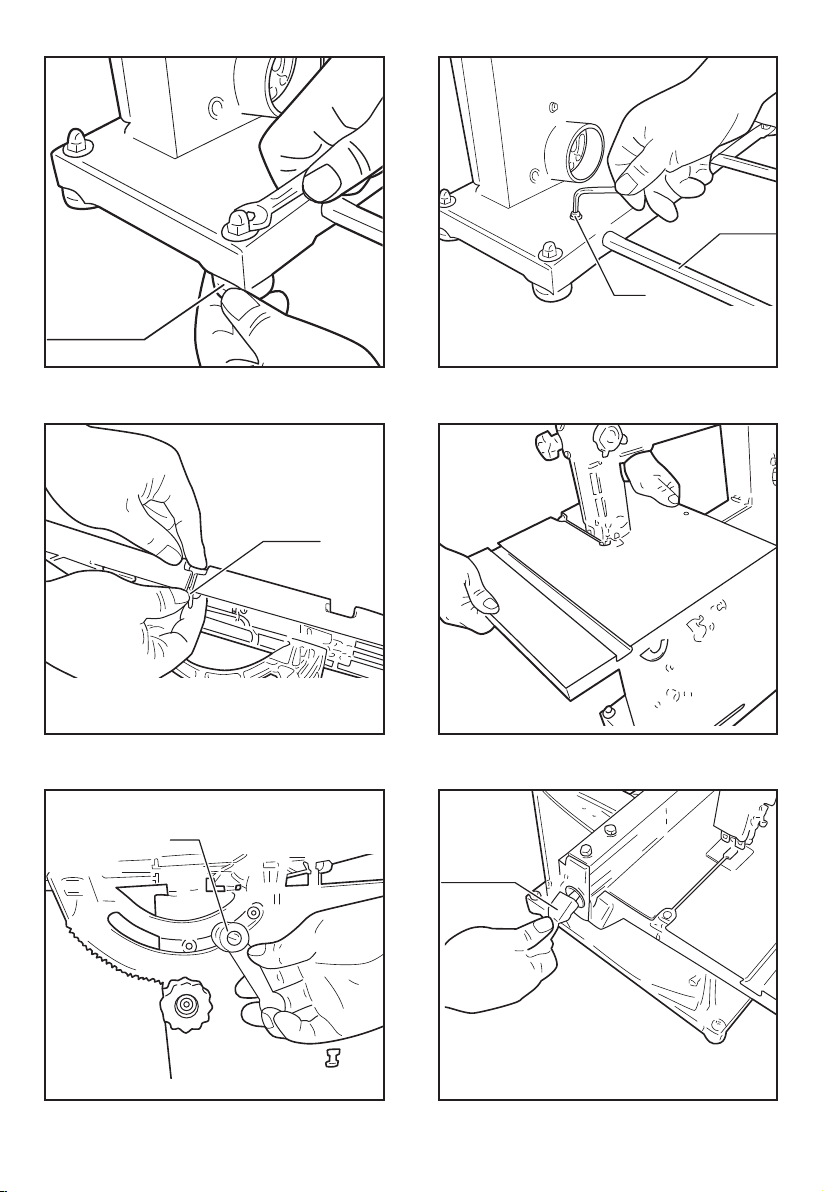
REMOVING BLADE (Fig.9)
WARNING: Disconnect band saw from power source
when changing or adjusting blades. Wear leather gloves
when handling band saw blades. Never wear gloves when
operating saw.
●Turn blade tension lever on the back of the tool
clockwise all the way until it locks in position to release
blade tension (see Figure 9).
●Release two latches on the side of the tool and open
upper and lower doors.
NOTE: When opening doors, make sure latches are
completely free from tabs on frame.
Remove table locking insert located in the front
of the table slot, take out the released blade and
replace with another blade.
INSTALLING BLADE
●Although most of the adjustments are not changed when
blade is removed, every adjustment should be checked
prior to using a newly installed blade.
●Make sure blade teeth are pointing down towards table.
Turn blade inside out if necessary.
●Slip new blade into table slot and over the upper and
lower blade wheels. Slide blade in between blade
guards.
●Tension blade by turning blade tensioning lever
counterclockwise, as far as it will go (see Figure 9).
●This is a spring loaded, tensioning mechanism and it will
automatically apply required tension to the blade.
● Use the tension knob to make ne adjustments to blade
tension.
●Close the doors and fasten latches.
●NOTE: When closing doors, make sure that the edges
attempting to secure door. This is necessary for proper
operation of dust collection system. The latches will not
pull the doors and frame together.
●Install table insert.
●Track blade as described in the following sections.
TRACKING BLADE
Refer to Figures 9 and 12.
WARNING: Be very careful; Improperly tracked blade
may spring out from wheels causing serious injury. Do not
perform tracking adjustment while band saw is running.
●Disconnect band saw from power source.
●To check the blade tracking, rotate drive wheel by hand
in clockwise direction. View blade through tracking
window.
●Proper tracking is achieved when driver and idler wheels
are aligned. Tracking knob on the back of the tool frame
is used to tilt upper wheel and align blade wheels.
●If blade rides away from cabinet, turn knob clockwise. If
blade rides toward cabinet, turn knob counterclockwise.
●When blade is tracking properly, secure position by
tightening nut.
BLADE GUIDES
NOTE: Adjust blade guides only after blade has been
properly tensioned and tracked.
●Blade guides support blade at sides and rear of blade,
and prevent twisting or deection.
●Blade guides should not touch blade when no workpiece
is in contact with blade. Adjust guides as described in
following section.
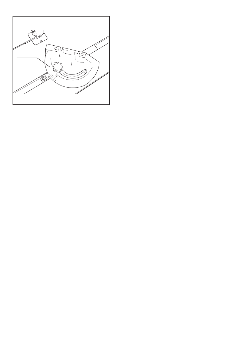
UPPER BLADE GUIDES (Fig.10-11)
●Upper blade guides employ guide pins for side support
and a ball bearing for rear support.
●Loosen screws and adjust guide pins to sides of the
blade (see Figure 10). Use a feeler gauge to check that
guide pins are 0.002” away from blade.
●Lock adjustment by tightening screw.
●Adjust ball bearing at rear of blade by loosening socket
head bolt and repositioning shaft (see Figure 11).
●Position ball bearing 0.002” away from back of blade.
●Secure position of bearing by tightening socket head
bolt.
●Adjust the height of upper guide to clear the workpiece
by 1/4”. Loosen upper guide knob and adjust height of
upper guide until it clears workpiece by 1/4”. Tighten
upper guide knob.
LOWER BLADE GUIDES (Fig.12)
●Lower blade guides employ guide pins for side support
and bearing for rear support.
●Loosen screws (see Figure 12) and move guide pins
away from blade sides.
●Loosen socket head bolts and adjust lower guide bracket
position so that rear of blade is positioned 0.002” away
from bearing.
●Tighten socket head bolts.
●Adjust guide pins to sides of the blade. Use a feeler
gauge to check that guide pins are 0.002” away from
blade.
●Lock adjustment by tightening screws.
BLADE SELECTION
●Blade vary depending on type of material, size of
workpiece and type of cut that is being performed.
●Characteristics which make blades different are width,
thickness and pitch.
BLADE WIDTH
●Width of blade describes distance from tip of a tooth to
back of blade.
●Width of blade affects rigidity of blade. A wider blade
wanders less and produces a straighter cut.
●Width of blade also limits the smallest radius which can
be cut. A 1/4” wide blade can cut about a 1/2” radius.
BLADE THICKNESS
●Blade thickness describes the distance between sides
of blade. A thicker blade has more rigidity and stronger
teeth.
●A narrow thick blade is used to cut curves while a wide
thin blade is used to make long, straight cuts.
BLADE PITCH
●Pitch describes number of teeth per inch or tooth size. A
blade with more teeth per inch produces a smoother cut.
●The type of material being cut determines number of
teeth that should be in contact with the workpiece.
●For soft materials, the proper blade has between 6 to 8
teeth per inch.
●When cutting hard materials, where shocking is more
detrimental, use a blade with 8 to 12 teeth per inch.
●There should always be at least three teeth in contact
with cut to avoid shocking blade.
●Blade shocking occurs when pitch is too large and blade
tooth encounters too much material. This can strip teeth
from blade.
●Blade manufactures are prepared to supply information
about blades for specic applications.