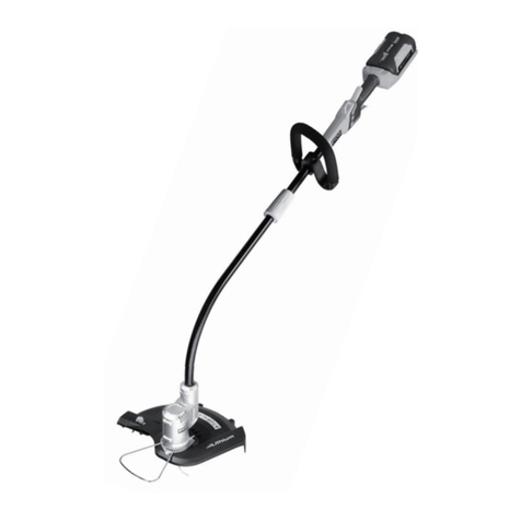
Ryobi RLT254CDSO User manual

ORIGINAL INSTRUCTIONS
RLT254CDSO
25.4CC GRASS TRIMMER
Important!
It is essential that you read the instructions in this manual before
assembling, maintaining and operating the product.

2
English (Original Instructions)
SYMBOLS
Important: Some of the following symbols may be used on your product. Please study them and learn their meaning.
Proper interpretation of these symbols will allow you to operate the product better and safer.
Explanation
Safety alert
Read and understand all instructions before operating the product, follow all warnings and safety
instructions.
Wear eye, hearing and head protection when operating the product.
Beware of thrown or flying objects. Keep all bystanders, especially children and pets, at least 15
m away from the operating area
The product is not intended for use with a toothed saw type blade.
Do not use metal blade (s) on the product
Rotational direction and maximum speed of the shaft for the cutting attachment.
Use unleaded gasoline intended for motor vehicle use with an octane rating of 91 ([R+M]/2) or
higher.
Use full synthetic 2-stroke lubricant for air cooled engines.
Mix the fuel mix thoroughly and also each time before refuelling.
Keep hands away from blades.
Run position
Set the choke lever to “FULL” choke position.
Set the choke lever to "HALF" choke position.
Press the primer bulb 10 times.

3
English (Original Instructions)
Squeeze the throttle lock and throttle trigger to run.
Wait 10 seconds.
Conforms to all regulatory standards in the country in the EU where the product is purchased.
EurAsian Conformity Mark
Ukrainian mark of conformity
109
Guaranteed sound power level
Pull the starter rope.
To reduce the risk of injury or damage, avoid contact with any hot surface.
Starting a warm engine by electrical starter
Starting a cold engine by electrical starter
Starting a warm engine by hand
Starting a cold engine by hand
The following signal words and meanings are intended to explain the levels of risk associated with the product.
SYMBOLS SIGNAL MEANING
DANGER Indicates an imminently hazardous situation, which, if not avoided, will
result in death or serious injury.
WARNING Indicates a potentially hazardous situation, which, if not avoided, could
result in death or serious injury.
CAUTION Indicates a potentially hazardous situation, which, if not avoided, may
result in minor or moderate injury.
CAUTION (Without Safety Alert Symbol) Indicates a situation that may result in
property damage.

4
English (Original Instructions)
■Never start or run the engine in a closed or poorly
ventilated area; breathing exhaust fumes can kill.
■Clear the work area before each use. Remove all
objects such as rocks, broken glass, nails, wire, or
string that can be thrown or become entangled in the
string head.
■Wear full eye and hearing protection while operating
the product. If working in an area where there is a risk
of falling objects, head protection must be worn.
■Hearing protection may restrict the operator’s ability
to hear warning sounds. Pay particular attention to
potential hazards around and inside the working area.
■Wear heavy, long trousers, non-slip protective
footwear, and gloves. Do not wear loose fitting
clothing, short trousers, jewellery of any kind, or use
with bare feet.
■Secure long hair so it is above shoulder level to
prevent entanglement in any moving parts.
■Keep all bystanders, children, and pets at least 15 m
away. Stop the product if anyone enters the area.
■Do not use the product when tired, ill, under medication,
or under the influence of alcohol and drugs.
■Do not use in poor lighting. The operator needs clear
unrestricted vision to identify potential hazards.
■Keep firm footing and balance at all times. Do not
overreach. Overreaching can result in loss of balance
or exposure to hot surfaces.
■Keep all parts of your body away from any moving
part.
■Do not touch the area around the silencer or cylinder
of the product, these parts get hot from operation.
■Always stop the engine and allow it to cool down
before making any adjustments.
■Do not smoke when mixing the fuel or when filling the
fuel tank.
■Mix and store the fuel in a container that is approved
for fuel.
■Mix the fuel outdoors where there are no sparks or
flames. Wipe up any fuel spillage. Move 9 m away
from refueling site before starting engine.
■Stop the engine and allow it to cool down before
refueling or storing the product.
■Allow the engine to cool; empty the fuel tank and
secure the product from moving before transporting in
a vehicle.
■Always stop the engine and make sure all moving
parts have come to stop before:
4
Safety performance, and dependability have been given
top priority in the design of your grass trimmer.
INTENDED USE
The grass trimmer is intended to be used only by adults who
have read and understood the instructions and warnings
in this manual and can be considered responsible for their
actions. The product is only intended for use outdoors in a
well-ventilated area. For safety reasons, the product must
be adequately controlled by a two-handed operation.
The product is designed for cutting grass, light weeds,
and other similar vegetation at or about ground level.
The cutting plane should be approximately parallel to the
ground surface.
The product should not be used to cut or trim hedges,
bushes, or other vegetation where the cutting plane is not
or about ground surface level.
Do not use the product for any other purpose.
WARNING
To reduce the risk of injury, the user must read and
understand the operator’s manual.
WARNING
Do not attempt to operate the product until you have
read thoroughly and understood completely all
instructions and safety rules contained in this manual.
Failure to comply may result in accidents involving
electric shock, re, and/or serious personal injury.
Save this operator’s manual and review frequently for
continuing safe operation and instructing others who
may use the product.
WARNING
The product is not intended to be used by children
or persons with reduced physical, mental or sensory
capabilities. Children should be adequately supervised
to ensure they do not play with the product.
GENERAL SAFETY WARNINGS
■For safe operation, read and understand all instructions
before using the product. Follow all safety instructions.
Failure to follow all safety instructions listed below, can
result in serious personal injury.
■Some regions have regulations that restrict the use of
the product. Check with your local authority for advice.
■Do not allow children or untrained individuals to use
the product.
5
English (Original Instructions)
●servicing
●leaving the product unattended
●cleaning your product
●changing accessories
●clearing blockages
●checking for any damage after hitting an object
●checking for any damage if the product starts to
vibrate abnormally
●performing maintenance
WARNING
Never use cutting means or attachments which are
not specied by RYOBI in this manual. This includes
the use of metal multi-piece pivoting chains and ail-
blades. These items are known to break up during use
and present a high risk of serious injury to the operator
or bystanders.
WARNING
Inspection after dropping or other impacts:
Thoroughly inspect the product and identify any
affections or damage with it. Any part that is damaged
should be properly repaired or replaced by an
authorised service centre.
GRASS TRIMMER SAFETY WARNINGS
■Replace the string head if cracked, chipped, or
damaged in any way. Be sure the string head is
properly installed and securely fastened. Failure to do
so can cause serious injury.
■Avoid using on wet grass.
■Do not walk backwards when using the product.
■Walk, never run.
■The small blade fitted to the cutting attachment guard
is designed to trim the new extended line to the correct
length for safe and optimum performance. It is very
sharp; do not touch it, particularly when cleaning the
product.
■Always ensure that ventilation openings are kept clear
of debris.
■Before use and after any impact, check that there
are no damaged parts. Examine the cutting means
for signs of cracking or other damage. A defective
switch or any part that is damaged should be properly
repaired or replaced by an authorised service facility.
■Make sure the head attachment is properly installed
5
and securely fastened.
■Make sure all guards, deflectors, handles, bolts, and
fasteners are properly and securely attached.
■Do not modify the product in any way. This may
increase the risk of injury to yourself or others.
■Use only the manufacturer’s replacement line in the
cutting head. Do not use any other cutting attachment.
■Never operate the product without the cutting
attachment guard in place and in good condition.
■Maintain a firm grip on both handles while trimming.
Keep string head below waist level. Never cut with
the string head located over 76 cm or more above the
ground.
TRANSPORTATION AND STORAGE
■Stop the engine and allow it to cool down before
storing or transporting.
■Clean all foreign materials from the product.
■Drain all fuel from tank into a container approved for
petrol. Remember to properly replace and tighten the
fuel cap.
■Run the engine until it stops, this will remove all fuel
that could become stale and leave varnish and gum
in the fuel system.
■Store the product in a cool, dry, and well-ventilated
place that is inaccessible to children. Keep away from
corrosive agents, such as garden chemicals and de-
icing salts. Do not store outdoors.
■When transporting the product in a vehicle, secure
it against movement or falling to prevent injury to
persons or damage to the product.
■Never carry or transport the product while the engine
is running.
■Abide all government and local regulations for the
safety storage and handling of petrol.
Short term
■Stop the engine and allow it to cool down before
storing.
■Clean all foreign material from the product.
■Store the product in a cool, dry, and well-ventilated
place that is inaccessible to children.
■Keep away from corrosive agents such as garden
chemicals and de-icing salts.
■Do not store outdoors.

6
English (Original Instructions)
RESIDUAL RISKS
Even when the product is used as prescribed, it is still
impossible to completely eliminate certain residual risk
factors. The following hazards may arise in use and
the operator should pay special attention to avoid the
following:
■Injury caused by vibration
– Hold the product by designated handles and restrict
working time and exposure.
■Exposure to noise can cause hearing injury
– Wear hearing protection and limit exposure.
■Eye injury due to flying debris
– Wear eye protection at all times.
RISK REDUCTION
It has been reported that vibrations from handheld tools
may contribute to a condition called Raynaud’s syndrome.
Symptoms may include tingling, numbness and blanching
of the ngers, usually apparent upon exposure to cold.
Hereditary factors, exposure to cold and dampness, diet,
smoking and work practices are all thought to contribute to
the development of these symptoms. There are measures
that can be taken by the operator to possibly reduce the
effects of vibration:
■Keep your body warm in cold weather. When operating
the product, wear gloves to keep the hands and wrists
warm. It is reported that cold weather is a major factor
contributing to Raynaud's Syndrome.
■After each period of operation, exercise to increase
blood circulation.
■Ensure that the product is correctly located in a
designated working position before operating the
product.
■Take frequent work breaks. Limit the amount of
exposure per day.
If you experience any of the symptoms of this condition,
immediately discontinue use and see your physician.
WARNING
Injuries may be caused, or aggravated, by prolonged
use of a tool. When using any tool for prolonged
periods, ensure you take regular breaks.
KNOW YOUR PRODUCT
1. Primer bulb
2. Choke lever
3. Fuel cap
4. Starter grip
5. Throttle lock
6. Ignition switch
7. Throttle trigger
8. Rear handle
9. Front handle
10. Shaft
11. Grass deflector
12. String head
13. Cutting line
14. Idle speed screw
15. Knob
16. Hanger cap
17. Bolt
18. Wing nut
19. Bump knob
20. Lower housing
21. Spool
22. String guide
23. Spring
24. Nut
25. Upper housing
26. Air box cover
27. Air filter
28. Spark plug
29. Metal spark plug boot
30. Rubber protect boot
31. Starter bit
32. Switch button
33. F/R button
34. Electrical starter
35. Starter bit shaft
36. Lock button
37. Guide recess
38. Best cutting area
39. Direction of cutter rotation
40. Screw
41. Mounting bracket
42. Tab
43. Slot
ASSEMBLY
UNPACKING
This product requires assembly.
■Carefully remove the tool and any accessories from
the box. Make sure that all items listed in the packing
list are included.
■Inspect the tool carefully to make sure no breakage or
damage occurred during shipping.
■Do not discard the packing material until you have
carefully inspected and satisfactorily operated the tool.

7
English (Original Instructions)
WARNING
If any parts are damaged or missing do not operate the
product until the parts are replaced. Failure to heed this
warning could result in serious personal injury.
WARNING
Do not attempt to modify the product or create
accessories not recommended for use with the product.
Any such alteration or modification is misuse and could
result in a hazardous condition leading to possible
serious personal injury.
WARNING
To prevent accidental starting that could cause serious
personal injury, always disconnect the engine spark
plug wire from the spark plug when assembling parts.
WARNING
Never attach or adjust any attachment while power
head is running. Failure to stop the engine may cause
serious personal injury.
WARNING
Be certain all knobs and fasteners are fully tightened
before operating the equipment.
check it periodically for tightness during use to avoid
serious injury.
PACKING LIST
■Trimmer
■Attachment shaft
■Front handle assembly
■Grass deflector
■Operator’s manual
■Figure sheet
ATTACHING THE FRONT HANDLE
See Fig. 2. (a)
■Loosen and remove the bolt and wing nut from the
front handle.
■Install the front handle onto the upper shaft at the
position between foam and warning label.
■Replace the bolt and wing nut and tighten wing nut
securely.
ATTACHING THE GRASS DEFLECTOR
See Fig. 2. (b)
■Insert the tab on the mounting bracket in the slot on
the grass deflector.
■Insert the screw into the grass deflector.
■Tighten the screw securely.
ATTACHING THE POWER HEAD TO TRIMMER
ATTACHMENT
See Fig. 2. (c)
WARNING
Never attach or adjust any attachment while power
head is running. Failure to stop the engine may cause
serious personal injury.
■The trimmer attachment connects to the power head
by means of a coupler device.
■Loosen the knob on the coupler of the power head
shaft and remove the end cap from the attachment.
■Push in the button located on the attachment shaft.
■Align the button with the guide recess on the power
head coupler and slide the two shafts together.
■Rotate the attachment shaft until the button locks into
the positioning hole.
NOTE: If the button does not release completely in the
positioning hole, the shafts are not locked into place.
Slightly rotate from side to side until the button is locked
into place.
■Tighten the knob securely.
REMOVING THE ATTACHMENT FROM THE POWER
HEAD
■Loosen the knob.
■Push in the button and twist the shafts to remove and
separate the ends.
OPERATION
FUEL AND REFUELING
HANDLING THE FUEL SAFELY
■Always handle fuel with care, it is highly flammable.
■Always refuel outdoors where there are no sparks and

8
English (Original Instructions)
FILLING THE TANK
WARNING
Check for fuel leaks. If any are found, correct them
before using the saw to prevent fire or burn injury.
■Clean surface around fuel cap to prevent
contamination.
■Loosen fuel cap slowly to release pressure and to
keep fuel from escaping around the cap.
■Carefully pour fuel mixture into the tank. Avoid spillage.
■Prior to replacing the fuel cap, clean and inspect the
gasket.
■Immediately replace fuel cap and hand tighten. Wipe
up any fuel spillage. Move 9 m away from refuelling
site before starting engine.
NOTE: It is normal for smoke to be emitted from a new
engine during and after first use.
WARNING
Always shut off engine before fuelling. Never add fuel to
a machine with a running or hot engine. Move at least
9 m from refuelling site before starting the engine. Do
not smoke!
STARTING AND STOPPING
WARNING
Never start or run the engine inside a closed or poorly
ventilated area; breathing exhaust fumes can kill.
TO START A COLD ENGINE:
See Fig. 4. (a)
NOTE: Lay the product on the ground. Ensure the cutting
means will not contact anything when it starts to rotate.
1. Press the primer bulb 10 times.
NOTE: After the 7th press, the fuel should be visible
in the primer bulb. If not, continue pressing until the
fuel is visible.
2. Set the choke lever to choke position.
3. Hold down the throttle lock and then squeeze the
throttle trigger. Keep the throttle trigger squeezed
completely following steps 3 to 7. Pull the starter
grip until the engine attempts to start. Do not pull the
starter grip more than 4 times.
4. Set the choke lever to choke position.
flames. Do not inhale fuel vapour. Do not smoke.
■Do not let petrol or lubricant come in contact with your
skin.
■Keep petrol and lubricant away from the eyes. If petrol
or lubricant comes in contact with the eyes, wash
them immediately with clean water. If irritation is still
present, see a doctor immediately.
■Clean up spilled petrol immediately.
■Always transport and store fuel in a container approved
for petroleum.
MIXING THE FUEL
See Fig. 3.
■This product is powered by a 2-stroke engine and
requires pre-mixing petrol and 2-stroke lubricant.
Premix unleaded petrol and 2-stroke engine lubricant
in a clean container approved for petrol.
■This engine is certified to operate on unleaded petrol
intended for motor vehicle use with an octane rating of
91 ([R + M]/2) or higher.
■Do not use any type of pre-mixed petrol / lubricant from
fuel service stations, this includes the pre-mixed petrol /
lubricant intended for use in mopeds, motorcycles, etc.
■Use synthetic 2-stroke lubricant only. Do not use
automotive lubricant or 2-cycle outboard lubricant.
■Mix 2% synthetic 2-stroke lubricant into the petrol. This
is a 50:1 ratio.
■Mix the fuel thoroughly and also each time before
refuelling.
■Mix in small quantities. Do not mix quantities larger
than usable in a 30-day period. A synthetic 2-stroke
lubricant containing a fuel stabiliser is recommended.
1 l + 20 ml =
2 l + 40 ml =
3 l + 60 ml = 50:1
4 l + 80 ml =
5 l + 100 ml =

9
English (Original Instructions)
5. Pull the starter grip until the engine starts. Do not pull
the starter grip more than 6 times.
NOTE: If the engine does not start, repeat the
procedure from step 2.
6. Allow the engine to run for 10 seconds.
7. Set the choke lever to position.
TO START A WARM ENGINE:
See Fig. 4. (b)
1. Press the primer bulb 10 times.
2. Set the choke lever to choke position.
3. Hold down the throttle lock and then squeeze the
throttle trigger completely and pull the starter grip until
the engine starts. Do not pull the starter grip more
than 6 times.
STARTING THE ENGINE USING AN ELECTRICAL
STARTER (OPTIONAL):
WARNING
Only use the RYOBI OES18 electrical starter. Use of any
other starter may damage the engine and cause serious
personal injury.
WARNING
Before using the electrical starter to start the product,
please read and understand completely the operation
manual of the OES18 electrical starter to avoid improper
operation and serious personal injury.
TO START A COLD ENGINE BY ELECTRICAL
STARTER:
See Fig. 12. (a)
1. Install the starter bit into the electrical starter with the
pentagon bit facing outside.
2. Push the F/R button to the left until the pentagon
symbol shows on the F/R button.
3. Lay the product on the ground and make sure that the
cutting means do not come in contact with anything.
4. Press the primer bulb 10 times.
NOTE: After the 7th press, the fuel should be visible
in the primer bulb. If not, continue pressing until the
fuel is visible.
5. Set the choke lever to choke position.
6. Hold down the throttle lock and then squeeze the
throttle trigger completely with your left hand and
keep the throttle trigger squeezed completely through
steps 6 to 12.
7. Use your right hand to put the starter bit shaft to the
shaft hole on the engine. Make sure the starter bit is
properly engaged.
NOTE: The electrical starter is equipped with a safety
interlock. Do not press and hold on the switch button
when putting the electrical starter shaft into the shaft
hole on the engine, otherwise the starter will not turn.
The starter will not turn if the electrical starter is not
properly engaged.
8. Press and hold the electrical starter switch button
until the engine attempts to start. Do not press the
electrical starter for more than 4 seconds.
9. Set the choke lever to choke position.
10. Press and hold the electrical starter switch button
until the engine starts.
NOTE: If the engine does not start, repeat the
procedure from step 5. Do not repeat the procedure
more than 1 time. If the engine does not start after
the second attempt, see the solution instruction for the
"Flooded engine" in the "Troubleshooting" section of
this manual.
11. Allow the engine to warm up for 10 seconds.
12. Set the choke level to choke position.
TO START A WARM ENGINE BY ELECTRICAL
STARTER:
See Fig. 12. (b)
1. Install the starter bit into the electrical starter with the
pentagon bit facing outside.
2. Push the F/R button to the left until the pentagon
symbol shows on the F/R button.
3. Lay the product on the ground and make sure that the
cutting means do not come in contact with anything.
4. Press the primer bulb 10 times.
5. Set the choke lever to position.
6. Hold down the throttle lock and then squeeze the
throttle trigger completely with your left hand and
keep the throttle trigger squeezed completely. Use
the right hand to put the electrical starter shaft into
the shaft hole on the engine. Make sure the starter is
properly engaged.
7. Press and hold the electrical starter switch button
until the engine starts.
NOTE: If the engine does not start, repeat the
procedure from step 5. Do not repeat the procedure
more than 1 time. If the engine does not start after
the second attempt, see the solution instruction for the
"Flooded engine" in the "Troubleshooting" section of
this manual.
TO STOP THE ENGINE:
■Set the switch to the “O” (OFF) position.

10
English (Original Instructions)
OPERATING THE GRASS TRIMMER
See Fig. 5.
Hold the product with the right hand on the rear handle
and the left hand on the front handle. Keep a rm grip
with both hands while in operation. The product should
be held at a comfortable position with the trigger handle
about hip height.
Always operate the product at full throttle. Prolonged
cutting at partial throttle will result in lubricant dripping from
the silencer. Cut tall grass from the top down. This will
prevent grass from wrapping around the shaft housing and
bump head which may cause damage from overheating. If
grass becomes wrapped around the bump head, stop the
engine, and remove the grass.
CUTTING TIPS
See Fig. 6.
■Avoid hot surfaces by always keeping the tool away
from your body. (Proper operating position shown in
figure 5.)
■Keep the product tilted toward the area being cut; this
is the best cutting area.
■The product cuts when passing the product from
right to left. This will avoid throwing debris at the
operator. Avoid cutting in the dangerous area shown
in illustration.
■Use the tip of the string to do the cutting; do not force
the string head into the uncut grass.
■Wire and picket fences cause extra string wear, even
breakage.
■Stone and brick walls, kerbs and wood may wear
string rapidly.
■Avoid trees and shrubs. Tree bark, wood mouldings,
cladding and fence posts can be easily damaged by
the string.
ADVANCING THE LINE
See Fig. 7.
Line advance is controlled by tapping the string head on
grass while running engine at full throttle.
■Run engine at full throttle.
■Tap the knob on ground to advance string. The string
advances each time the head is tapped. Do not hold
the knob on the ground.
NOTE: The line trimming cut-off blade on the grass
deector will cut the line to the correct length.
NOTE: If the string is worn too short, you may not be able
to advance the string by tapping it on the ground. If so,
stop the engine, and manually advance the line.
ADVANCING THE CUTTING LINE MANUALLY
■Stop the engine.
■Push the knob in while pulling on string(s) to manually
advance the line.
MAINTENANCE
WARNING
Use only original manufacturer’s replacement parts,
accessories and attachments. Failure to do so can
cause possible injury, poor performance and may void
your warranty.
■Always stop the engine and allow it cool before making
any maintenance.
■ You may make adjustments and repairs described
in this user manual. For other repairs, contact the
authorized service agent.
■Consequences of improper maintenance may
include excess carbon deposits resulting in loss of
performance and discharge of black oily residue
dripping from the silencer.
■For replacement line, use only nylon filament line of
the diameter described in the specification table of this
manual.
■After extending new cutter line, always return the
product to its normal operating position before starting.
■The cutting attachment must not work in idle mode. If
this requirement is not satisfied, the clutch has to be
adjusted or the machine needs an urgent maintenance
by a qualified technician.
■After each use, clean the product with a soft dry cloth.
■Check all nuts, bolts and screws at frequent intervals
for proper tightness to ensure the product is in safe
working condition. Any part that is damaged should be
properly repaired or replaced by an authorised service
centre.
Maintenance schedule
Check if fastener is fully
tightened
Before each use

11
English (Original Instructions)
Check: Cutting attachment
must not rotate in idle mode ²
Before each use
Check fuel hose Before each use
Check all hose connections Before each use
Clean fuel tank and lter 1 Every 3 months or 50 hours
of operation
Replace fuel lter 1Every year or after 300
hours or operation
Check fuel cap or fuel tank
vapor vent (if equipped) for
leakage
Before each use
Clean air lter Every 25 hours
Change air lter Every year or after 300
hours or operation
Clean or adjust spark plug Every 6 months or 100
hours of operation
Replace spark plug Every year or after 300
hours or operation
Clean spark arrestor Every 25 hours
Replace spark arrestor Every year or after 300
hours or operation
Clean the exhaust port
and silencer
Every 25 hours
1 These items should only be carried out by an authorised service
centre.
2 If this requirement is not met, contact an authorised service centre
for repair or adjustment.
STRING HEAD REPLACEMENT
See Fig. 8a.
■Stop the engine.
■Align the spanner along both flat side of arbor flange
washer.
■Turn the string head counterclockwise by hand to
remove old one.
■Replace a new string head, align the nut in the string
head to the connector shaft of lower boom.
■Turn the string head clockwise by hand to tighten,
recommended torque is 6 N.M.
LINE REPLACEMENT
See Fig. 8.
■Ensure the product is in the off position.
■Use a 2.4 mm diameter monofilament string.
■Stop the engine.
■Cut one piece of string approximately 6 m in length.
■Rotate the bump knob clockwise as necessary to align
the arrows on the bump knob with the arrows on the
lower housing of string head.
■Insert one end of the string into the eyelet located on
the side of the string head and push until string comes
out through eyelet on the other side.
■Continue to push string through the string head until
the middle section of the string is inside the string head
and string outside the string head is evenly divided on
each side.
■Rotate the knob on the string head clockwise to wind
the line.
■Wind the string until approximately 20 cm remains
protruding from the string head.
CLEANING THE EXHAUST PORT AND MUFFLER
Depending on the type of fuel used, the type and amount
of lubricant used, and/or your operating conditions, the
exhaust port and silencer may become blocked with
carbon deposits. If you notice a power loss with your gas-
powered tool, a qualied service technician will need to
remove these deposits to restore performance.
SPARK ARRESTOR
The spark arrestor must be cleaned or replaced every
25 hours to ensure proper performance of your product.
Spark arrestors may be in different locations depending on
the model purchased. Please contact your nearest service
dealer for the location of the spark arrestor for your model.
CLEANING THE AIR FILTER
See Fig. 9.
For proper performance and long life, keep the air lter
clean.
■Ensure the product is in the off position.
■Remove the air filter cover.
■Remove the air filter and clean it with warm soapy water.
■Rinse, and let the air filter dry completely.
■Work two drops of lubricant into the air filter.

12
English (Original Instructions)
■Replace the air filter (fits only one way).
■Replace the air filter cover.
NOTE: The lter should be replaced annually for best
performance.
FUEL CAP
WARNING
A leaking fuel cap is a re hazard and must be replaced
immediately.
The fuel cap contains a non-serviceable lter and a
check valve. A clogged fuel lter will cause poor engine
performance. If performance improves when the fuel cap
is loosened, check valve may be faulty or lter clogged.
SPARK PLUG REPLACEMENT
See Fig. 10.
WARNING
The material of the spark plug is metal. It becomes very
hot after you stop the engine. Wait for the engine to cool
down before disassembling the metal spark plug boot to
avoid personal injury.
NOTE: This engine uses a Champion RCJ-6Y or
equivalent with 0.63 mm (0.025 in.) electrode gap. Use an
exact replacement and replace annually.
1. Stop the engine.
2. Hold the front portion of the rubber protect boot and
pull it away from the housing.
3. Pull the rubber protect boot upward to release the
hook.
4. Twist the metal spark plug boot and pull it away from
the spark plug.
5. Loosen the spark plug by turning it counter clockwise
with a wrench. Remove the old spark plug and replace
with a new one. Assemble back the metal spark plug
boot and the rubber protect boot.
ATTACHING THE HANGER CAP
See Fig. 11.
To use the hanger cap, push in the button and place the
hanger cap over the lower end of the attachment. Slightly
rotate the cap from side to side until the button locks into
place.
NOTE: The secondary hole in the attachment shaft can be
used for hanging purposes as well.

13
English (Original Instructions)
TROUBLESHOOTING
IF THESE SOLUTIONS DO NOT SOLVE THE PROBLEM, CONTACT YOUR AUTHORISED SERVICE DEALER.
PROBLEM POSSIBLE CAUSE SOLUTION
Engine will not start. 1. No spark. 1. The spark plug may be damaged, remove it and check
for dirt and cracks. Replace with a new spark plug.
2. No fuel. 2. Push primer bulb until bulb is full of fuel. If bulb does
not ll, primary fuel delivery system is blocked. Contact
a servicing dealer. If primer bulb lls, engine may be
ooded, proceed to next item.
3. Engine is ooded. 3. Remove spark plug, turn product so spark plug hole
is aimed at the ground. Rotate the choke dial to “ ”
position and pull starter cord 10 to 15 times. This will
clear excess fuel from engine. Remove any fuel which
splashed on the product. Clean and reinstall spark plug.
Clean up any spilled fuel and move at least 9m away
before restarting. Pull starter three times with choke
dial at “ ”. If engine does not start, rotate choke dial
to “ ” position and repeat normal starting procedure.
If engine still fails to start, repeat procedure with a new
spark plug.
4. Starter rope is hard to pull. 4. Contact a servicing dealer.
5. Old fuel 5. Only use fresh fuel mixed with recommended oil. Fuel
over 30 days old may prevent the product from starting.
Engine starts but will not
accelerate.
Engine requires approximately
three minutes to warm up.
Allow engine to completely warm up. If engine does
not accelerate after three minutes, contact a servicing
dealer.
Engine starts but will only run at
high speed at half choke.
Carburetor requires adjustment. Contact a servicing dealer.
Engine does not reach full
speed and emits excessive
smoke.
1. Check lubricant fuel mixture. 1. Use fresh fuel and the correct 2-stroke lubricant mix.
2. Air lter is dirty. 2. Clean air lter. Refer to Cleaning the Air Filter earlier
in this manual.
3. Spark arrestor screen is dirty. 3. Contact a servicing dealer.

14
English (Original Instructions)
20161117v2d1
PROBLEM POSSIBLE CAUSE SOLUTION
Engine starts, runs, and
accelerates but will not idle.
Idle speed screw on
carburetor
requires adjustment
Contact a servicing dealer.
Line will not advance. 1. Line welded to itself. 1. Lubricate with silicone spray.
2. Not enough line on spool. 2. Install more line. Refer to "Line Replacement" earlier
in this manual.
3. Line worn too short. 3. Pull lines while alternately pressing down on and
releasing bump head.
4. Line tangled on spool. 4. Remove line from spool and rewind. Refer to "Line
Replacement” earlier in this manual.
5. Engine speed too slow. 5. Advance line at full throttle.
Grass wraps round shaft
housing and bump head
1. Cutting tall grass at ground
level.
1. Cut tall grass from the top down.
2. Operating the product at part
throttle
2. Operate the product at full throttle.
Bump knob hard to turn. Screw threads dirty or damage. Clean threads and lubricate with grease - if no
improvement, replace bump knob.
Lubricant drips from mufer. 1. Operating the product at part
throttle.
1. Operate the product at full throttle.
2. Lubricant/fuel mixture is
incorrect.
2. Use fresh fuel and correct synthetic 2-stroke lubricant
mix.
3. Air lter is dirty. 3. Clean per instruction in "Maintenance" section.
Bar and chain running hot and
smoking.
Chain tension for overtightened
condition.
Tension chain. Refer to chain tension earlier in this
manual.
Chain oil tank is empty. Check oil tank.
Motor runs, but chain is not
rotating.
Chain tension is too tight. Retention chain. Refer to chain tension earlier in

this manual.
Check guide bar and chain
assembly.
Refer to replacing the bar and chain earlier in this
manual.
Check guide bar and chain for
damage.
Inspect guide bar and chain for damage.

15
English (Original Instructions)
SPECIFICATION
Grass Trimmer RLT254CDSO
Weight
- Without fuel, cutting attachment
and harness 4.06 kg
- Without fuel and harness, with
string trimmer head 4.87 kg
Fuel tank volume 580 cm3
Cutting swath 420 mm
Engine displacement 25.4 cm3/ cc
Line diameter 2.4 mm
Maximum engine performance (in
accordance with ISO 8893) 0.75 kW
Maximum rotational frequency of
the spindle 12,000 min-1
Engine speed (rotational frequency)
at idle 2,600-3,400 min-1
Fuel consumption (
in accordance
with ISO
8893)
at max. engine
performance
0.38 kg/h
Specic fuel consumption (in
accordance with ISO 8893) at max.
engine performance
0.5 kg/h
Vibration (in accordance with ISO 22867):
Front handle
- Idling 5.9 m/s2
- Racing 6.1 m/s2
- Equivalent vibration total value 6.0 m/s2
Rear handle
- Idling 3.6 m/s2
- Racing 5.6 m/s2
- Equivalent vibration total value 4.7 m/s2
Uncertainty K 1.5 m/s2
Noise emission (in accordance with ISO 22868)
A-weighted emission sound
pressure level at the operator
position
- Idling 72.4 dB (A)
- Racing 94.1 dB (A)
- Equivalent A-weight emission
sound pressure level 91.1 dB (A)
Uncertainty 2.5 dB
A-weighted emission sound power
level
- Idling 84.0 dB (A)
- Racing 106.2 dB (A)
- Equivalent A-weight sound power
level 106.2 dB (A)
Uncertainty 2.5 dB
REPLACEMENT PARTS
Parts Accessory
Number Part number
String head RAC151 000998619 /
5132003334
Spare string line
RAC104 (15m) 099900005 /
5132002641
RAC105 (50 m) 099900006 /
5132002642
Grass deector N/A 5131039526

RYOBI® WARRANTY APPLICATION CONDITIONS
In addition to any statutory rights resulting from the purchase, this product is covered by a warranty as stated below.
1. The warranty period is 24 months for consumers and commences on the date the product was purchased. This
date has to be documented by an invoice or other proof of purchase. The product is designed and dedicated
to consumer and private use only. So there is no warranty provided in case of professional or commercial use.
This warranty applies only on new products.
2. There is a possibility to extend for a part of the range of power tools (AC/DC) the warranty period over the
period described above using the registration on the www.ryobitools.eu website. The eligibility of products for
extended warranty is clearly displayed in stores and / or on packaging and is contained within the product
documentation. The end user is required to register his/her newly-acquired products online within 30 days from
the date of purchase. The end user may register for the extended warranty in his/her country of residence if
listed on the online registration form where this option is valid. Furthermore, end users must give their consent
to the storage of their personal data that is required to be entered online. They must also accept the terms and
conditions. The registration confirmation receipt, which is sent out by e-mail, and the original invoice showing
the date of purchase will serve as proof of the extended warranty.
3. The warranty covers all defects of the product during the warranty period due to faults in workmanship or
material at the purchase date. The warranty is limited to repair and/or replacement and does not include any
other obligations including but not limited to incidental or consequential damages. The warranty is not valid if
the product has been misused, used contrary to the instruction manual, or has been incorrectly connected to
a power supply. This warranty does not apply to:
– any damage to the product that is the result of improper or lack of maintenance
– any product that has been altered or modified
– any product where original identification (trade mark, serial number) markings have been defaced, altered or
removed
– any damage caused by non-observance of the instruction manual
– any product not displaying the CE approval mark on the rating plate
– any product that has been attempted to be repaired by a non-authorised warranty service centre or without prior
authorisation by Techtronic Industries
– any product connected to an improper power supply (amps, voltage, frequency)
– any product used with inappropriate fuel mixture (fuel, oil, Ratio of oil / fuel mixture)
– any damage caused by external influences (water, chemical, physical, shocks) or foreign substances
– normal wear and tear spare parts
– inappropriate use, overloading of the tool
– use of non-approved accessories or parts
– Accessories provided with the tool or purchased separately including but not limited to blades, saw chains,
cutting lines etc.
– Any periodic adjustments to or maintenance cleaning of carburetors
– Components (parts and accessories) subject to natural wear and tear, including but not limited to bump knobs,
drive belts, clutch, blades of hedge trimmers or lawn mowers, harness, cable throttle, carbon brushes, power
cord, tines, felt washers, hitch pins, blower fans, blower and vacuum tubes, vacuum bag and straps, guide bars,
saw chains, hoses, connector fittings, spray nozzles, wheels, spray wands, inner reels, outer spools, cutting
lines, spark plugs, air filters, gas filters, mulching blades, etc.
4. For servicing, the product must be sent or presented to a RYOBI authorised service station listed for each
country in the following list of service station addresses. In some countries your local RYOBI dealer undertakes
to send the product to the RYOBI service organisation. When sending a product to a RYOBI service station,
the product should be safely packed without any dangerous contents such as petrol, marked with sender’s
address and accompanied by a short description of the fault.
5. A repair / replacement under this warranty is free of charge. It does not constitute an extension or a new start
of the warranty period. Exchanged parts or products become our property. In some countries delivery charges
or postage will have to be paid by the sender. Your statutory rights arising from the purchase of the product
remain unaffected.
6. This warranty is valid in the European Community, Switzerland, Iceland, Norway, Liechtenstein, Turkey and
Russia. Outside these areas, please contact your authorised RYOBI dealer to determine if another warranty
applies.

AUTHORISED SERVICE CENTRES
ACD PLANT LTD
145 Southbank Road
Coundon
Coventry, West Midlands
CV6 1FG
Phone: 02476 594348
Email: [email protected]
Web: www.acdplant.co.uk
CBS Power Tools Limited
Unit 4, V P Square
Storeys Bar Rd, Fengate
Peterborough, Cambridgeshire
PE1 5YS
Phone: 01733 343031
Email: [email protected]
Web: www.cbspowertools.com
C D Powertools
76 Old Road
Churwell Morley, Leeds
LS27 7TH
Phone: 0113 2718494
Email: [email protected]
Web : www.cdpowertools.co.uk
C J Sinclair Limited
44 Victoria Road
St Peters
Broadstairs, Kent
CT10 2UG
Phone: 01843 869400
Email: [email protected]
Web: www.cjsinclairltd.co.uk
Powertech Ind Ltd
Unit 2C, Ellison Road
Norwood Ind, Killamarsh
Sheffield, South Yorkshire
S21 2JG
Phone: 01142 474080
Email: [email protected]
Web: www.powertech-industrial.co.uk
RYCKO Technical Services LTD
104 Green Lane
St Albans, Herts
AL3 6EX
Phone: 08458 678790
Email: [email protected]
Web: www.ryckotechnical.com
ToolTech Industrial Equipment
227 E Dunhill Road, Macosquin
Coleraine, Co Londonderry
BT514LQ
Phone: 028 70359493
Email: [email protected]
For an updated list of authorised service centres, visit http://en.ryobitools.eu/header/service-and-support/service-agents.

DECLARATION OF CONFORMITY
Techtronic Industries GmbH
Max-Eyth-Straße 10, 71364 Winnenden, Germany
Herewith we declare that the product
Grass Trimmer
Brand: RYOBI
Model number: RLT254CDSO
Serial number range: 46208702000001 -46208702999999
is in conformity with the following European Directives and harmonised standards
2006/42/EC, 2014/30/EU, 2000/14/EC, 2005/88/EC, 2016/1628/EU, 2011/65/EU,
EN ISO 11806-1:2011, EN ISO 14982:2009, EN 50581:2012
Measured sound power level: 107.2 dB (A)
Guaranteed sound power level: 109 dB (A)
Conformity assessment method to Annex V Directive 2000/14/EC amended by 2005/88/EC.
Floyd Jeffrey Nesom (BSME)
Vice President of Engineering
Winnenden, Jul. 20, 2018
Authorised to compile the technical file:
Alexander Krug, Managing Director
Techtronic Industries GmbH
Max-Eyth-Straße 10, 71364 Winnenden, Germany


Techtronic Industries GmbH
Max-Eyth-Straße 10,
71364 Winnenden, Germany
960405044-03
Other manuals for RLT254CDSO
3
Table of contents
Other Ryobi Trimmer manuals

Ryobi
Ryobi EVT350RG Operation manual

Ryobi
Ryobi RY24200 Quick setup guide

Ryobi
Ryobi RHT6060RS User manual

Ryobi
Ryobi RLT1830H13 User manual

Ryobi
Ryobi RY40640 User manual

Ryobi
Ryobi OLT1832 User manual

Ryobi
Ryobi RLM13E33S User manual

Ryobi
Ryobi P2008 User manual

Ryobi
Ryobi RY29550 User manual

Ryobi
Ryobi Expand-It RY15523A User manual

Ryobi
Ryobi RBC52FSBHO User manual

Ryobi
Ryobi ACMD01 User manual

Ryobi
Ryobi RY15523 User manual

Ryobi
Ryobi RY15522 User manual

Ryobi
Ryobi BC30 RY30260 User manual

Ryobi
Ryobi rlt4025 User manual

Ryobi
Ryobi P2001 User manual

Ryobi
Ryobi 725rE User manual

Ryobi
Ryobi OLT1825 User manual

Ryobi
Ryobi ONE+ P2607 User manual