Ryobi RLT26CDS User manual

RLT26CDS
COUPE-BORDURES MANUEL D’UTILISATION 1
STRING TRIMMER USER’S MANUAL 10
KANTENSCHNEIDER BEDIENUNGSANLEITUNG 18
RECORTADORA DE HILO MANUAL DE UTILIZACIÓN 27
TAGLIABORDI MANUALE D’USO 36
APARADOR DE RELVA MANUAL DE UTILIZAÇÃO 45
GRASTRIMMER GEBRUIKERSHANDLEIDING 54
TRIMMER INSTRUKTIONSBOK 63
TRÅDTRIMMER BRUGERVEJLEDNING 71
TRÅDTRIMMER BRUKSANVISNING 79
SIIMALEIKKURI KÄYTTÄJÄN KÄSIKIRJA 87
SZEGÉLYVÁGÓ HASZNÁLATI ÚTMUTATÓ 95
STRUNOVÁ SEKAČKA NÁVOD K OBSLUZE 104
ÅÖçáéäéëÄ êìäéÇéÑëíÇé èé ùäëèãìÄíÄñàà 112
TRIMMER MANUAL DE UTILIZARE 121
PODKASZARKA DO OBRZEŻY INSTRUKCJA OBSŁUGI 130
KOSILNICA Z NITKO UPORABNIŠKI PRIROČNIK 139
©I©A» KORISNI»KI PRIRU»NIK 148
TRIMMER KASUTAJAJUHEND 157
ŽOLIAPJOVĖ NAUDOJIMO VADOVAS 166
ROKAS PĻAUJMAŠĪNA LIETOTĀJA ROKASGRĀMATA 175
STRUNOVÁ KOSAČKA - VYŽÍNAČ NÁVOD NA POUŽITIE 184
íêàåÖê êöäéÇéÑëíÇé áÄ ìèéíêÖÅÄ 193
Important! It is essential that you read the instructions in this manual before mounting and operating
this machine.
FR
EN
DE
ES
IT
PT
NL
SV
DA
NO
FI
HU
CS
RU
RO
PL
SL
HR
ET
LT
LV
SK
BG
960401009-03.indd AI960401009-03.indd AI 2010/4/28 4:562010/4/28 4:56

Attention ! Il est indispensable que vous lisiez les instructions contenues dans ce manuel avant
le montage et la mise en service de l’appareil.
Important! It is essential that you read the instructions in this manual before mounting and operating
this machine.
Achtung! Bitte lesen Sie unbedingt vor Montage und Inbetriebnahme die Hinweise dieser Bedienungsanleitung.
¡Atención! Es imprescindible que lea las instrucciones de este manual antes del montaje y de la
puesta en servicio.
Attenzione! Prima di procedere al montaggio e alla messa in funzione, è indispensabile leggere
attentamente le istruzioni del presente manuale.
Atenção! É indispensável ler as instruções deste manual antes de montar e pôr em serviço.
Let op ! Het is absoluut noodzakelijk vóór montage en inbedrijfstelling de aanwijzingen in deze
handleiding te lezen.
Observera! Det är nödvändigt att läsa instruktionerna i denna bruksanvisning före montering och
driftsättning.
OBS! Denne brugsanvisning skal læses igennem inden montering og ibrugtagning.
Advarsel! Vennligst les instruksjonene i denne bruksanvisningen før du monterer og tar i bruk
maskinen.
Huomio! On ehdottoman välttämätöntä lukea tässä käyttöohjeessa annetut ohjeet ennen
asennusta ja käyttöönottoa.
!
Figyelem! Feltétlenül fontos, hogy a jelen használati útmutatóban foglalt előírásokat az
összeszerelés és az üzembe helyezés ellőt elolvassa!
Důležité upozornění! Před montáží nářadí a uvedením do provozu je nutné si přečíst následující pokyny.
ÇÌËχÌËe! èee‰ Ò·ÓÍÓÈ Ë Á‡ÔÛÒÍÓÏ ËÌÒÚÛÏeÌÚ‡ ÌeÓ·ıÓ‰ËÏÓ ÔÓ˜eÒÚ¸ ËÌÒÚÛ͈ËË ËÁ ̇ÒÚÓfl˘e„Ó
ÛÍÓ‚Ó‰ÒÚ‚‡.
Atenie! Este indispensabil sã citii instruciunile coninute în acest mod de utilizare înainte de montaj
i de punerea în funciune.
Uwaga! Przed montowaniem i uruchomieniem, koniecznie musicie się Państwo zapoznać
z zaleceniami zawartymi w niniejszym sposobie użycia.
Pomembno! Zelo pomembno je, da pred namestitvijo in prvo uporabo te naprave preberete
navodila v tem priročniku.
Upozorenje!
Vaæno je da upute u ovom KorisniËkom priruËniku proËitate prije postavljanja i uporabe ovog alata.
Dikkat! Montajdan ve aletin kullanımına başlamadan bu kılavuzda bulunan talimatları
okumanız gerekmektedir.
Tähtis! Lugege enne seadme kokkupanekut ja kasutamist kindlasti läbi selles juhendis
sisalduvad eeskirjad ja juhised!
Dėmesio! Prieš surinkdami ir paleisdami aparatą į darbą, reikia, kad jūs perskaitytumėte šiame
vadove esančias instrukcijas.
Uzmanību! Ir ļoti būtiski, lai jūs izlasītu norādījumus, kas sniegti šajā rokasgrāmatā, pirms ķeraties
pie ierīces montēšanas un iedarbināšanas!
Upzornenie! Je dôležité, aby ste si pred montážou a spustením zariadenia prečítali pokyny, ktoré sa
nachádzajú v tomto návode.
ÇÌËχÌËÂ! èÂ‰Ë Ò„ÎÓ·fl‚‡ÌÂ Ë ÔÛÒ͇Ì ̇ χ¯Ë̇ڇ  ‚‡ÊÌÓ ‰‡ ÔÓ˜ÂÚÂÚ ËÌÒÚÛ͈ËËÚ ‚
˙ÍÓ‚Ó‰ÒÚ‚ÓÚÓ Á‡ ÛÔÓÚ·‡.
960401009-03.indd AII960401009-03.indd AII 2010/4/28 4:562010/4/28 4:56

10
English(Original instructions)
EN
FR DE ES IT PT NL SV DA NO FI HU CS RU RO PL SL HR ET LT LV SK BG
10
SYMBOLS
Important: Some of the following symbols may be used on your tool. Please study them and learn their meaning.
Proper interpretation of these symbols will allow you to operate the tool better and safer.
NAME EXPLANATION
Safety Alert Symbol Indicates danger, warning or caution. It means attention!!! Your safety is
involved.
Read Your Operator's Your manual contains special messages to bring attention to potential
Manual safety concerns as well as operating and servicing information. Please
read all the information carefully to ensure satisfaction and safe use.
Wear eye, hearing Wear eye, hearing and head protection when operating this equipment.
Keep bystanders away Keep all bystanders at least 15 m away.
Ricochet Danger of Ricochet.
No blade Do not install any type of blade on this unit.
RPM Decal Rotational direction and maximum speed of the shaft for the cutting
attachment.
Boots Wear non-slip safety footwear when using this equipment.
Gloves Wear non-slip, heavy-duty gloves.
No Smoking Do not smoke when mixing fuel or filling fuel tank.
Petrol Use unleaded gasoline intended for motor vehicle use with an octane
rating of 91 ([R+M]/2) or higher.
Oil Use synthetic 2-stroke oil for air cooled engines.
Mix Petrol and Oil Mix the fuel mix thoroughly and also each time before refuelling.
and head protection
960401009-03.indd 10960401009-03.indd 10 2010/4/28 4:562010/4/28 4:56

11
English(Original instructions)
EN
FR DE ES IT PT NL SV DA NO FI HU CS RU RO PL SL HR ET LT LV SK BG
Thank you for buying a Ryobi trimmer.
Your new trimmer has been engineered and manu-
factured to Ryobi’s high standard for dependability, ease
of operation, and operator safety. Properly cared for, it will
give you years of rugged, trouble-free performance.
INTENDED USE
This product should only be used outdoors.
The product is intended for cutting long grass, weed, and
similar vegetation at or about ground level. The cutting
plane should be approximately parallel to the ground
surface. The product should not be used to cut or trim
hedges, bushes or other vegetation where the cutting
plane is not parallel to the ground surface.
WARNING
To reduce the risk of injury, the user must read
and understand the operator’s manual.
WARNING
Do not attempt to operate this trimmer until you
have read thoroughly and understood completely
all instructions, safety rules etc contained in
this manual. Failure to comply may result in
accidents involving fire, electric shock or serious
personal injury. Save operator’s manual and
review frequently for continuing safe operation,
and instructing others who may use this tool.
READ ALL INSTRUCTIONS.
GENERAL SAFETY RULES
Q For safe operation, read and understand all
instructions before using the trimmer. Follow all safety
instructions. Failure to follow all safety instructions
listed below, can result in serious personal injury.
Q Do not allow children or untrained individuals to use
this unit.
Q Never start or run the engine in a closed or poorly
ventilated area; breathing exhaust fumes can kill.
Q Clear the work area before each use. Remove all
objects such as rocks, broken glass, nails, wire,
or string which can be thrown or become entangled in
the bump head.
Q Wear full eye and hearing protection while operating
this unit.
Q Wear heavy long pants, boots, and gloves. Do not
wear loose fitting clothing, short pants, jewellery of
any kind, or use with bare feet.
Q Secure long hair so it is above shoulder level to
prevent entanglement in any moving parts.
Q Keep all bystanders, children, and pets at least 15 m
away.
Q Do not operate this unit when you are tired, ill, or
under the influence of alcohol, drugs, or medication.
Q Do not operate in poor lighting.
Q Keep firm footing and balance. Do not overreach.
Overreaching can result in loss of balance or
exposure to hot surfaces.
Q Keep all parts of your body away from any moving part.
Q Do not touch area around the muffler or cylinder of
the trimmer, these parts get hot from operation.
Q Always stop the engine and remove the spark plug
wire before making any adjustments or repairs except
for carburetor adjustments.
Q Inspect the unit before each use for loose fasteners,
fuel leaks, etc. Replace any damaged parts before use.
Q The string head will rotate during carburetor
adjustments.
Q It has been reported that vibrations from hand-held
tools may contribute to a condition called Raynaud’s
Syndrome in certain individuals. Symptoms may
include tingling, numbness and blanching of the
fingers, usually apparent upon exposure to cold.
Q Hereditary factors, exposure to cold and dampness,
diet, smoking and work practices are all thought to
contribute to the development of these symptoms.
Q It is presently unknown what, if any, vibrations or extent
of exposure may contribute to the condition. There are
measures that can be taken by the operator to possibly
reduce the effects of vibration:
a) Keep your body warm in cold weather. When
operating the unit wear gloves to keep the hands
and wrists warm. It is reported that cold weather is
a major factor contributing to Raynaud’s Syndrome.
b) After each period of operation, exercise to increase
blood circulation.
11
SYMBOLS
NAME EXPLANATION
Switch On/Off Switch
I = ON to Run
O = OFF to Stop
Conforms to all regulatory standards in the country in the EU where
the product is purchased.
960401009-03.indd 11960401009-03.indd 11 2010/4/28 4:562010/4/28 4:56
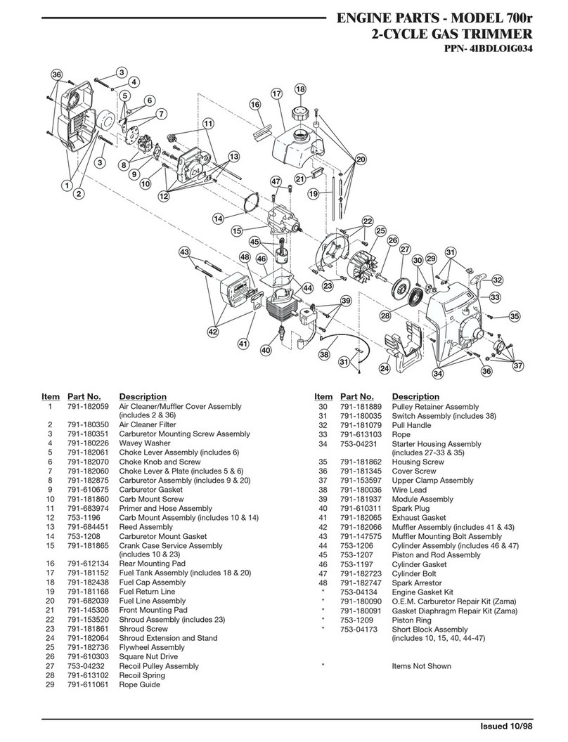
12
English(Original instructions)
EN
FR DE ES IT PT NL SV DA NO FI HU CS RU RO PL SL HR ET LT LV SK BG
c) Take frequent work breaks. Limit the amount of
exposure per day.
Q If you experience any of the symptoms of this condition,
immediately discontinue use and see your physician
about these symptoms.
Q Keep the tool well maintained, fasteners tightened
and worn parts replaced.
Q Mix and store fuel in a container approved for fuel.
Q Mix fuel outdoors where there are no sparks or flames.
Wipe up any fuel spillage. Move 9 m away from
refueling site before starting engine.
Q Stop the engine and allow to cool before refueling or
storing the unit.
Q Allow the engine to cool; empty the fuel tank and
secure the unit from moving before transporting in a
vehicle.
SPECIFIC SAFETY RULES FOR TRIMMER USE
Q Replace bump head if cracked, chipped, or damaged
in anyway. Be sure the bump head is properly
installed and securely fastened. Failure to do so can
cause serious injury.
Q Make sure all guards, straps, deflectors and handles
are properly and securely attached.
Q Use only the manufacturer's replacement line in the
cutting head. Do not use any other cutting attachment.
Q Never operate unit without the safety guard in place
and in good condition.
Q Maintain a firm grip on both handles while trimming.
Keep bump head below waist level. Never cut with
the bump head located over 76 cm or more above the
ground.
12
SPECIFICATION
RLT26CDS
Weight (kg)
- Without fuel, without string head, without guard 3.98
- Without fuel with string head 4.35
Fuel tank volume [cm3 or (L)] 250 or (0.25)
Cutting swath (mm) 432
Engine displacement (cm3/ cc) 26
Line diameter (mm) 2.0
Maximum engine performance
(in accordance with ISO 8893) (kW) 0.65
Maximum rotational frequency
of the the spindle (min-1) 12,000
Engine speed (rotational frequency)
at recommended max. spindle
rotational frequency (min-1) 12,000
Engine speed (rotational frequency)
at idle (min-1) 2,800-3,800
Fuel consumption (in accordance
with ISO 8893) at max.
engine performance [kg/h or (L/h)] 0.33 or (0.45)
Specific fuel consumption
(in accordance with ISO 8893)
at max. engine performance [g/kW.h or (L/kW.h)] 508 or (0.7)
Vibration level idling (m/s2)
- Front handle 7.7
- Rear handle 4.5
Vibration level racing (m/s2)
- Front handle 11.1
- Rear handle 12.9
Sound pressure level
(in accordance with EN ISO 22868) [LpA (dB A)] 100
Measured sound pressure level (dB A) 108
Sound power level (in accordance
with EN ISO 22868) [LwA (dB A)] 109
960401009-03.indd 12960401009-03.indd 12 2010/4/28 4:562010/4/28 4:56

13
English(Original instructions)
EN
FR DE ES IT PT NL SV DA NO FI HU CS RU RO PL SL HR ET LT LV SK BG
DESCRIPTION
Please refer to Fig.1
1. Primer Bulb
2. Choke Lever
3. Fuel Cap
4. Starter Grip
5. On / Off Switch
6. Throttle Trigger
7. Rear Handle
8. Front Handle
9. Shaft
10. Safety Guard
11. Bump Head
12. Cutting Line
13. Knob
14. Throttle Lock
15. Idle Speed Screw
ASSEMBLY
Please refer to Fig. 2.
WARNING
If any parts are damaged or missing, do not
operate this tool until the parts are replaced.
Failure to heed this warning could result in
serious personal injury.
WARNING
Do not attempt to modify this product or create
accessories not recommended for use with this
product. Any such alteration or modification is
misuse and could result in a hazardous condition
leading to possible serious personal injury.
WARNING
To prevent accidental starting that could cause
serious personal injury, always disconnect the
engine spark plug wire from the spark plug when
assembling parts.
WARNING
Never attach or adjust any attachment while
power head is running. Failure to stop the engine
may cause serious personal injury.
WARNING
Be certain the knob is fully tightened before
operating equipment; check it periodically for
tightness during use to avoid serious injury.
OPERATION
Read the operation manual and follow all
warnings and safety instructions.
Wear eye protection and ear protection.
Keep all bystanders, especially children and
pets, at least 15 m from the operating area.
FUEL AND REFUELING
HANDLING THE FUEL SAFELY
Q Always handle fuel with care, it is highly flammable.
Q Always refuel outdoors where there are no sparks
and flames. Do not inhale fuel vapors.
Q Do not let petrol or oil come in contact with your skin.
Q Keep petrol and oil away from the eyes. If petrol
or oil comes in contact with the eyes, wash them
immediately with clean water. If irritation is still
present, see a doctor immediately.
Q Clean up spilled petrol immediately.
MIXING THE FUEL (Fig. 3)
Q This product is powered by a 2-stroke engine and
requires pre-mixing petrol and 2-stroke oil. Pre-mix
unleaded petrol and 2-stroke engine oil in a clean
container approved for petrol.
Q This engine is certified to operate on unleaded petrol
intended for automotive use with an octane rating
of 91 ([R + M] / 2) or higher.
Q Do not use any type of pre-mixed petrol / oil from fuel
service stations, this includes the pre-mixed petrol / oil
intended for use in mopeds, motorcycles, etc.
Q Use synthetic 2-stroke oil only. Do not use automotive
oil or 2-stroke outboard oil.
Q Mix 2% synthetic 2-stroke oil into the petrol. This is a
50:1 ratio.
Q Mix the fuel thoroughly and also each time before
fueling.
Q Mix in small quantities. Do not mix quantities larger
than usable in a 30 day period. Synthetic 2-stroke oil
containing a fuel stabilizer is recommended.
FILLING THE TANK
Q Clean surface around fuel cap to prevent
contamination.
Q Loosen fuel cap slowly to release pressure and to
keep fuel from escaping around the cap.
Q Carefully pour fuel mixture into the tank. Avoid spillage.
13
960401009-03.indd 13960401009-03.indd 13 2010/4/28 4:562010/4/28 4:56

14
English(Original instructions)
EN
FR DE ES IT PT NL SV DA NO FI HU CS RU RO PL SL HR ET LT LV SK BG
Q Prior to replacing the fuel cap, clean and inspect
the gasket.
Q Immediately replace fuel cap and hand tighten.
Wipe up any fuel spillage. Move 9 m away from
refueling site before starting engine.
Note: It is normal for smoke to be emitted from a new
engine during and after first use.
WARNING
Always shut off engine before fueling. Never add
fuel to a machine with a running or hot engine.
Move at least 9 m from refueling site before
starting engine. Do not smoke!
1 Litre + 20 ml =
2 Litres + 40 ml =
3 Litres + 60 ml = 50:1 (2%)
4 Litres + 80 ml =
5 Litres + 100 ml =
STARTING AND STOPPING (Fig. 4)
WARNING
Never start or run the engine inside a closed or
poorly ventilated area; breathing exhaust fumes
can kill.
NOTE: Be sure to return the stop switch to the "I" (RUN)
position before trying to start unit.
To start a cold engine:
DO NOT squeeze the throttle trigger until the engine
starts and runs.
Lay the trimmer on a flat, bare surface.
PRIME - Press the primer bulb 10 times.
SET the start lever to the START position.
PULL the rope quickly and sharply straight up until
the engine starts.
Then squeeze the trigger to run.
NOTE: Squeezing and releasing the throttle trigger
releases the start lever to the RUN position.
If the engine stalls, set the start lever to the RUN position
"". Then pull starter rope until the unit starts.
To start a warm engine:
Make sure carburettor is set to RUN position.
PULL the rope quickly and sharply straight up until the
engine starts.
To stop the engine:
Press and hold the switch in the stop “ O ” position until
the engine stops.
OPERATING THE TRIMMER (Fig. 5)
Hold the trimmer with the right hand on the rear handle
and the left hand on the front handle. Keep a firm grip
with both hands while in operation. Trimmer should be
held at a comfortable position with the rear handle about
hip height.
Always operate trimmer at full throttle. Cut tall
grass from the top down. This will prevent grass from
wrapping around the shaft housing and bump head
which may cause damage from overheating. If grass
becomes wrapped around the bump head, stop the
engine, disconnect the spark plug wire, and remove the
grass. Prolonged cutting at partial throttle will result in oil
dripping from the silencer.
CUTTING TIPS (Fig. 6)
When cutting make sure the cutter head is at a slight angle
as shown while still approximately parallel to the ground
surface. In tall grass cut from the top down to ensure the
moving parts do not get tangled with the long grass.
Move the head in steady strokes from right to left as you
work through the grass.
ADVANCING THE LINE (Fig. 7)
If the line becomes short, tap the head on the ground
as shown to extend more line. Take care not to ‘crash’ it
against a hard surface.
MAINTENANCE
WARNING
Use only original manufacturer's replacement
parts, accessories and attachments. Failure to
do so can cause possible injury, poor perfor-
mance and may void your warranty.
You may make adjustments and repairs described
here. For other repairs, have the trimmer serviced by
an authorised service agent.
Consequences of improper maintenance may
include excess carbon deposits resulting in loss of
performance and discharge of black oily residue
dripping from the silencer.
Make sure all guards, straps, deflectors and handles
are properly and securely attached to avoid the risk of
personal injury.
the cutting attachment must not rotate in idle mode. If
this requirement is not satisfied, the idle speed needs
adjustment (Fig.10) or the machine needs an urgent
maintenance by a qualified technician.
14
960401009-03.indd 14960401009-03.indd 14 2010/4/28 4:562010/4/28 4:56

15
English(Original instructions)
EN
FR DE ES IT PT NL SV DA NO FI HU CS RU RO PL SL HR ET LT LV SK BG
SPOOL REPLACEMENT (Fig. 11)
LINE REPLACEMENT (Fig. 11)
Ensure the unit is in the off position
Remove the spark plug lead, to prevent accidental
starting.
Use 2.4mm diameter monofilament string.
Cut one piece of string approximately 6.0m in length
Rotate knob on string head until line on knob aligns
with arrows on top of string head.
Insert one end of string into eyelet located on the
side of the string head and push until string comes
out through eyelet on the other side. Continue to
push string through the string head until the middle
section of the string is inside the string head and
string outside the string head is evenly divided on
each side.
Rotate the knob on the string head counterclockwise
to wind the string
Wind the string until approximately 20cm remains
protruding from the string head.
CLEANING THE EXHAUST PORT AND
SILENCER
Depending on the type of fuel used, the type and amount
of oil used, and/or your operating conditions, the exhaust
port and silencer may become blocked with carbon
deposits. If you notice a power loss with your petrol
powered tool, a qualified service technician will need to
remove these deposits to restore performance.
SPARK ARRESTOR
The spark arrestor must be cleaned or replaced every
25 hours or yearly to ensure proper performance of
your product. Spark arrestors may be in different
locations depending on the model purchased. Please
contact your nearest service dealer for the location of the
spark arrestor for your model.
CLEANING THE AIR FILTER SCREEN (Fig. 8)
For proper performance and long life, keep air filter
screen clean.
Remove the air filter cover by pushing down on the latch
with your thumb while gently pulling on the cover.
Brush the air filter screen lightly to clean.
Replace the air filter cover by inserting the tabs on the
bottom of the cover into the slots on the air filter base;
push the cover up until it latches securely in place.
FUEL CAP
WARNING
A leaking fuel cap is a fire hazard and must be
replaced immediately.
The fuel cap contains a non-service able filter and a
check valve. A clogged fuel filter will cause poor engine
performance. If performance improves when the fuel cap
is loosened, check valve may be faulty or filter clogged.
Replace fuel cap if required.
SPARK PLUG REPLACEMENT (Fig. 9)
This engine uses a Champion RCJ-6Y or NGK BPMR7A
spark plug with .05 in. electrode gap. Use an exact
replacement and replace annually.
IDLE SPEED ADJUSTMENT (Fig. 10)
If the cutting attachment turns at idle, the idle speed
screw needs adjusting on the engine. Turn the idle speed
screw counterclockwise to reduce the idle RPM and
stop the cutting attachment movement. If the cutting
attachment still moves at idle speed, contact a service
dealer for adjustment and discontinue use until the repair
is made.
STORING THE PRODUCT
Clean all foreign material from the product. Store
idle unit indoors in a dry, well-ventilated area that is
in- accessible to children. Keep away from corrosive
agents such as garden chemicals.
Abide by all ISO and local regulations for the safe
storage and handling of petrol.
When storing 1 month or longer:
Drain all fuel from tank into a container approved for
petrol. Run engine until it stops.
15
960401009-03.indd 15960401009-03.indd 15 2010/4/28 4:562010/4/28 4:56

16
English(Original instructions)
EN
FR DE ES IT PT NL SV DA NO FI HU CS RU RO PL SL HR ET LT LV SK BG
16
TROUBLESHOOTING
IF THESE SOLUTIONS DO NOT SOLVE THE PROBLEM, CONTACT YOUR AUTHORISED SERVICE DEALER.
PROBLEM POSSIBLE CAUSE SOLUTION
Engine will not start. 1. Power switch is off.
2. No spark.
3. No fuel.
4. Engine is flooded.
5. Starter rope now harder to
pull than when new.
1. Make sure Switch is in the ON or "I" position
2. The spark plug may be damaged, remove it and
check for dirt and cracks. Replace with a new spark
plug.
3. Push primer bulb until bulb is full of fuel. If bulb
does not fill, primary fuel delivery system is blocked.
Contact a servicing dealer. If primer bulb fills, engine
may be flooded, proceed to next item.
4. Remove spark plug, turn unit so spark plug hole is
aimed at the ground. Set start lever to “ ” position
and pull starter cord 10 to 15 times. This will clear
excess fuel from engine. Remove any fuel which
splashed on the product. Clean and reinstall spark
plug. Clean up any spilled fuel and move at least
9m away before restarting. Pull starter three times
with with start lever at “ ”. If engine does not start,
set start lever to “ ” position and repeat normal
starting procedure. If engine still fails to start, repeat
procedure with a new spark plug.
5. Contact a servicing dealer.
Engine starts but will
not idle long enough to
engage throttle
Temperature can effect engine
idle time and rpm. Flip start lever to RUN “ ” position and pull starter
until engine starts.
Engine does not stop
when switch is turned
off
Electrical connection is loose/
unplugged
Set the start lever to CHOKE “ ” to stop the engine.
Immediately stop using the product. Check electrical
connection on the bottom of the trimmer and make
sure it is properly connected. Contact servicing dealer
if the problem persists.
Engine starts but will
not accelerate.
Engine requires approximately
three minutes to warm up.
Allow engine to completely warm up. If engine does
not accelerate after three minutes, contact a servicing
dealer.
Engine starts but will
only run at high speed
at half choke.
Carburetor requires
adjustment. Contact a servicing dealer.
Engine does not reach
full speed and emits
excessive smoke.
1. Check oil fuel mixture.
2. Air filter is dirty.
3.Spark arrestor screen is
dirty.
1. Use fresh fuel and the correct 2-stroke oil mix.
2. Clean air filter. Refer to Cleaning the Air Filter
Screen earlier in this manual.
3. Contact a servicing dealer.
Engine starts, runs,
and accelerates but will
not idle.
Idle speed screw on
carburetor requires
adjustment
Turn idle speed screw clockwise to increase idle speed.
(Fig.10) Ensure that after adjustment the cutting head
does not rotate at idle. Contact servicing dealer if the
problem persists.
960401009-03.indd 16960401009-03.indd 16 2010/4/28 4:562010/4/28 4:56

17
English(Original instructions)
EN
FR DE ES IT PT NL SV DA NO FI HU CS RU RO PL SL HR ET LT LV SK BG
Line will not advance. 1. Line welded to itself.
2. Not enough line on spool.
3. Line worn too short.
4. Line tangled on spool.
5. Engine speed too slow.
1. Lubricate with silicone spray.
2. Install more line. Refer to “Line Replacement” earlier
in this manual.
3. Pull lines while alternately pressing down on and
releasing bump head.
4. Remove line from spool and rewind. Refer to “Line
Replacement” earlier in this manual.
5. Advance line at full throttle.
Grass wraps round
shaft
housing and bump
head.
1. Cutting tall grass at ground
level.
2. Operating trimmer at part
throttle.
1. Cut tall grass from the top down.
2. Operate trimmer at full throttle.
Bump knob hard to turn. Screws threads dirty or
damaged.
Clean threads and lubricate with grease - if no
improvement, replace bump knob.
Oil drips from silencer.
1. Operating trimmer at part
throttle.
2. Check oil/fuel mixture.
3. Air filter dirty.
1. Operate trimmer at full throttle.
2. Use fresh fuel and the correct synthetic 2-stroke oil
mix.
3. Clean per instruction in Maintenance Section.
NOTE: If your unit exhibits specic performance problem(s) where the Troubleshooting section recommends a clockwise
screw adjustment on the carburetor and no adjustments have been made since original purchase, the unit should
be taken to an authorised service centre for repair. In most cases, the needed adjustment is a simple task for the
trained service representative.
960401009-03.indd 17960401009-03.indd 17 2010/4/28 4:562010/4/28 4:56

Other manuals for RLT26CDS
3
Table of contents
Other Ryobi Trimmer manuals

Ryobi
Ryobi RLT-310 Operation manual

Ryobi
Ryobi ONE+ OLT1833-0 User manual

Ryobi
Ryobi 150r User manual

Ryobi
Ryobi PLT-2543 Instructions for use

Ryobi
Ryobi RHT1851R15 User manual

Ryobi
Ryobi OHT1845 User manual

Ryobi
Ryobi OLT1825 User manual

Ryobi
Ryobi RHT1851R40 User manual

Ryobi
Ryobi RY36LT33A User manual

Ryobi
Ryobi OHT1850 User manual

Ryobi
Ryobi RLT5030 User manual

Ryobi
Ryobi CHT1850LBC User manual

Ryobi
Ryobi RY44140 User manual

Ryobi
Ryobi RBC38SB User manual

Ryobi
Ryobi PLT3043E, RY70103 User manual

Ryobi
Ryobi RY41002 Series User manual

Ryobi
Ryobi RHT-600R User manual

Ryobi
Ryobi 700r User manual

Ryobi
Ryobi R18XLTR20 User manual

Ryobi
Ryobi OLT1831 User manual