INSTALLATION—TOOLS AND EQUIPMENT REQUIRED
INSTALLATION
TOOLS AND EQUIPMENT REQUIRED
1. Socket and wrench set.
2. Concrete anchor bolts (1/2-in. diameter).
(See “ANCHORING METHODS” on page
3.)
3. Threaded rod (1/2-in. diameter).
(See “ANCHORING METHODS” on page
3.)
4. Two ladders (taller than the door opening height).
5. Forklift.
6. Carpenter’s level (4-ft. minimum length).
7. Carpenter’s square.
8. Hammer drill.
9. Masonry drill bit (1/2-in. diameter).
10. Three or four bar clamps (1-ft. length).
11. Hammer and mallets.
12. Crowbar or pry bar.
13. Assorted hand tools (pliers, tape measure, etc.).
14. Assorted shim stock.
15. Water level, line level, or transit.
3. The customer must guarantee 100% access to the
door opening during the installation. No traffic
should be allowed through the door during the
installation.
4. If an electrician is used, that person must make all
electrical connections. The electrician should be
present one hour after installation begins.
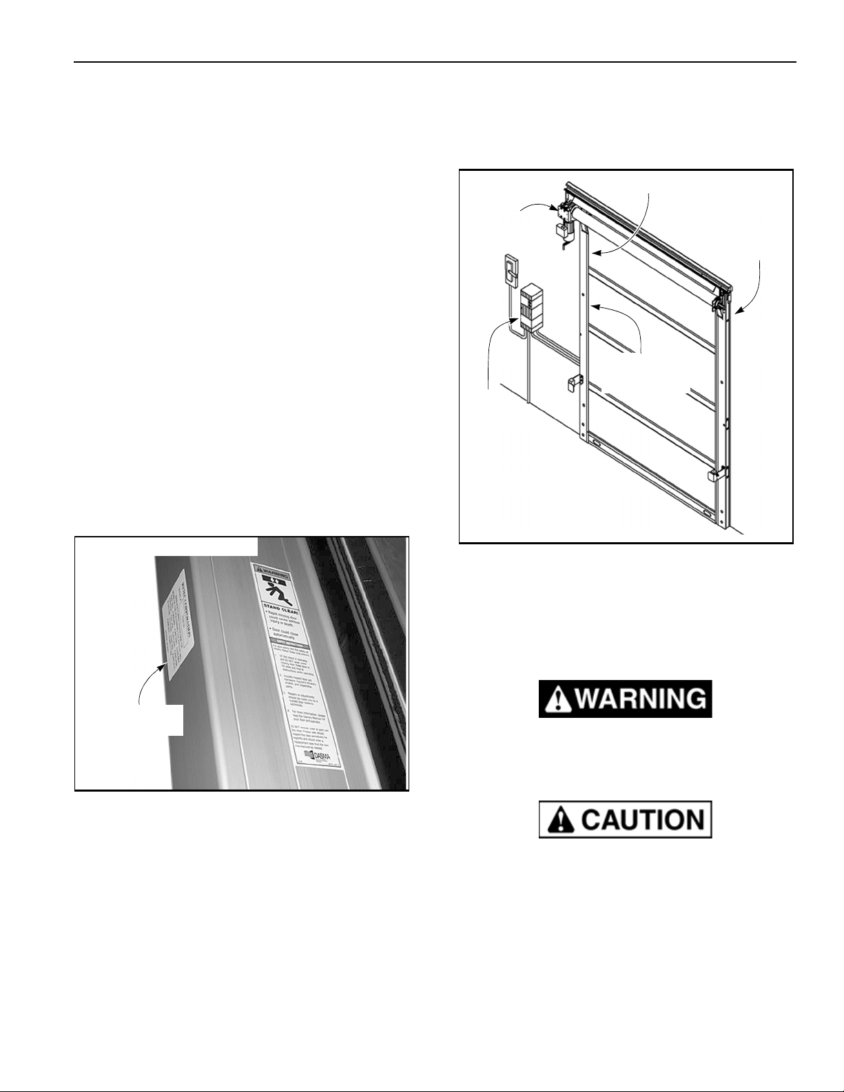
5. The Rytec control box and a fusible disconnect
should be installed prior to the start of the door
installation. (See Figure 1 for layout.)
ELECTRICIAN’S RESPONSIBLITIES
For complete details on the responsibilities of the
electrician, refer to the Rytec System 4 Drive & Control
Installation & Owner’s Manual.
GENERAL ARRANGEMENT OF DOOR PARTS
Figure 3 shows the location of the major components
of your
PredaDoor
NXT. This
illustration
should be
used as reference only and should not be used as part
of the installation instructions.
Drive Motor/Gearbox
Left Side Column
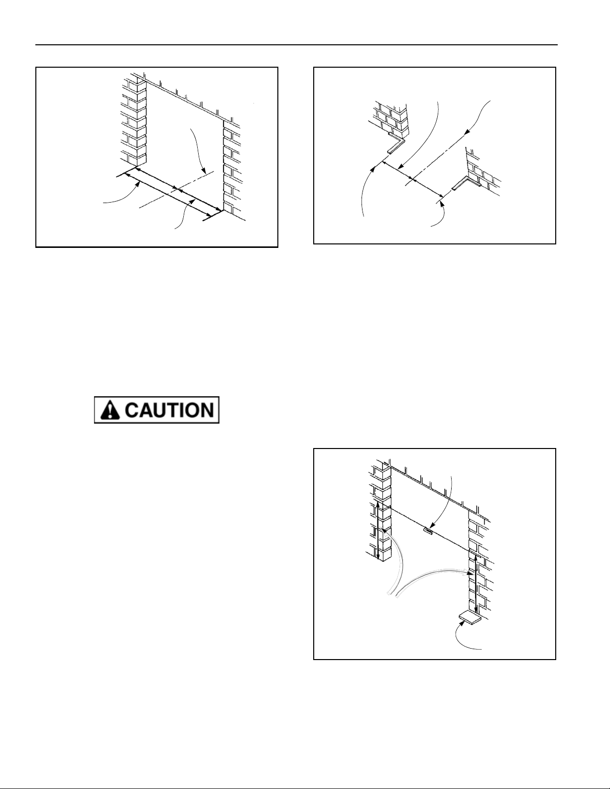
FLOOR LOOP EQUIPMENT REQUIREMENTS
1. Wet-type concrete saw.
2. Wet vac.
3. 200–500 feet of 16-gauge, 19-strand, type XLPE,
copper, crosslink polyethylene jacket wire (or
equivalent). The length of wire is determined by the
size of the loop.
4. Bondo® P606 flexible embedding sealer (or
equivalent) — required to fill grooves in floor. For
cold temperature sealing applications, Bondo P610
speed set must be added to the P606 to ensure
proper curing of the filler.
5. Water supply and garden hose (for concrete saw).
NOTE: For complete floor loop installation
instructions, refer to the installation
instructions provided with your floor loop.
BASIC JOB REQUIREMENTS
1. A forklift must be supplied by the customer, dealer,
or installer.
Fused
Disconnect
Rytec
System 4
Control Panel
Photo Eye
(Left)
A7700040
Bottom Bar
Figure 3
Fabric Roll
Photo Eye
(Right)
Right Side
Column
2. Two installers are required.
NOTE: One installer must be a qualified electrical
technician, and all electrical work must
meet applicable codes. If the installer is
not qualified, an electrician must be
present during installation.
NOTE: The above illustration shows the front side
of the door. Left and right are determined
when viewing the front side of the door.