Saab TankRadar G3 User manual

SERVICE MANUAL
MaC - Monitoring and Control System

2
Service Manual
G3 MaC Second edition, March 2000
Documentation for Saab TankRadar
The following documentation will be delivered to your vessel.
Operating Manual
The Operating Manual describes how to perform the everyday use
of the system, how to set up the system, and how to use it.
Service Manual
The Service Manual describes how to perform service, trouble
shooting, verification and maintenance of your system.
Training
If you are interesting in attending a training course for Saab TankRa-
dar, please contact Saab Marine Electronics’ After Sales department.
We arrange customized courses for small groups of people to fit
the needs of that group. The course can take place in our training
facilities in Gothenburg or wherever you should choose to have it.
www.saab.tankradar.com
Visit our website for updated information about the products, the
company and our service agents around the world, or to contact us.
G3 MaC Second edition, March 2000
Copyright © Saab Marine Electronics AB
Saab TankRadar and TankRadar are registered trademarks.
The contents, descriptions and specifications within this manual are
subject to change without notice. Saab Marine Electronics AB takes no
responsibility for any errors that may appear in this manual.
As each TankRadar G3 is specially designed for each delivery, the con-
tents and illustrations in this manual may differ from your
TankRadar G3 system.

3
G3 MaC Second edition, March 2000
Contents
Documentation for Saab TankRadar ................................................................................. 2
Training ................................................................................................................................... 2
www.saab.tankradar.com .................................................................................................... 2
1 Abbreviations .............................................................................5
2 System overview ........................................................................7
3 Equipment in the I/O Unit cabinet ...........................................9
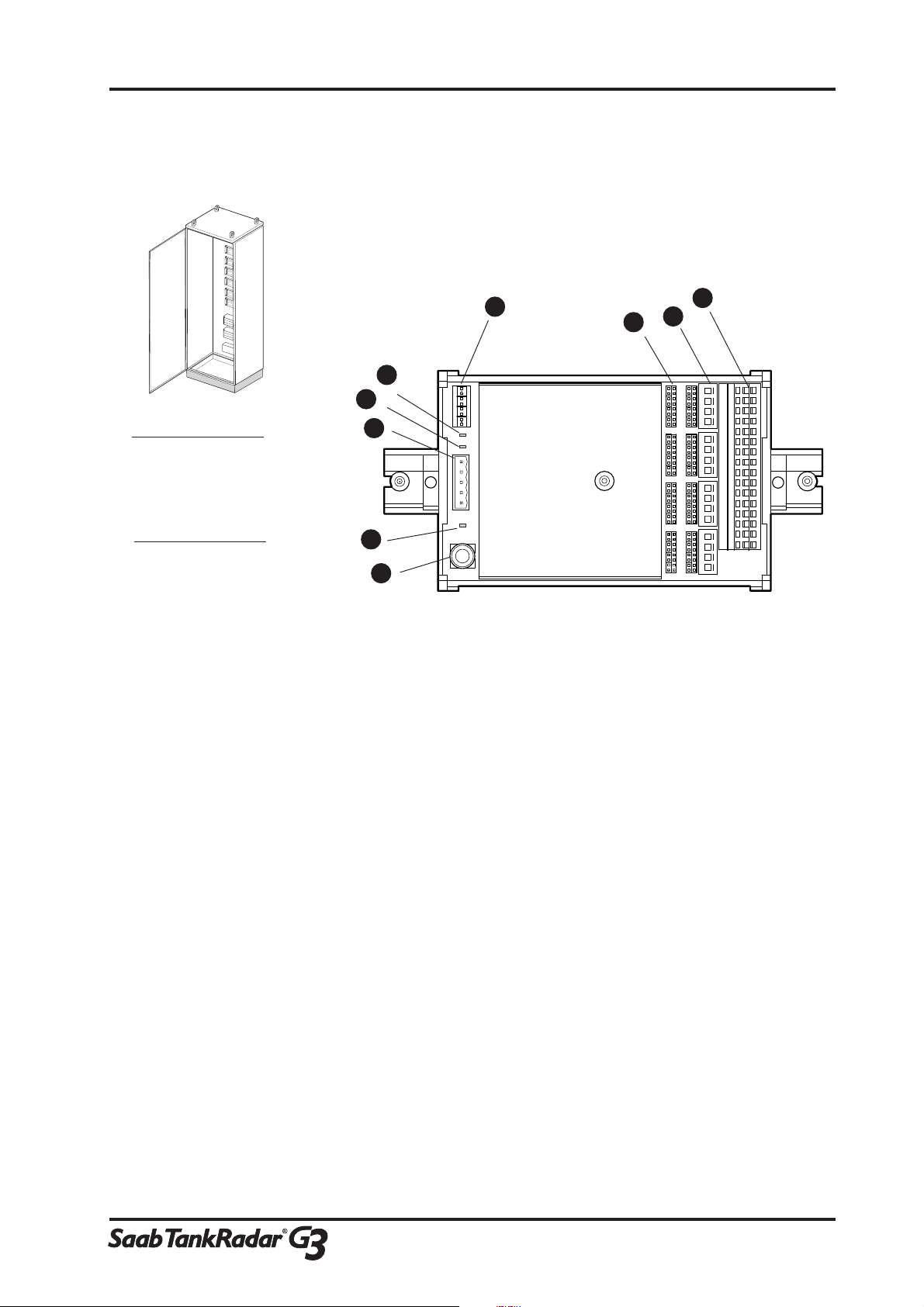
3.1 I/O Terminal Analog Input -description ................................................................ 9
LED´s ....................................................................................................................................................... 9
Fuses ........................................................................................................................................................ 9
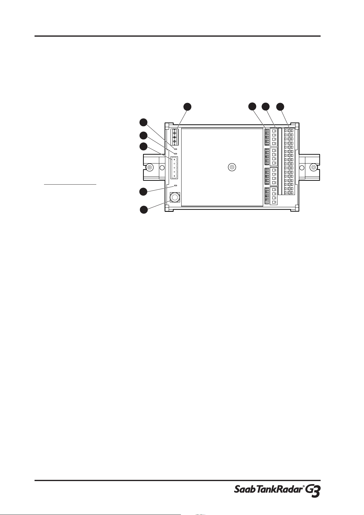
3.2 I/O Terminal Analog Output - description ......................................................... 10
LED´s ..................................................................................................................................................... 10
Fuses ...................................................................................................................................................... 10
3.3 I/O Terminal Digital Input - description ............................................................. 11
LED´s ..................................................................................................................................................... 11
3.4 I/O Terminal Digital Output - description ......................................................... 12
LED´s ..................................................................................................................................................... 12
3.5 I/O Terminals in I/O Unit - service...................................................................... 13
To replace a terminal ......................................................................................................................... 13
3.6 Power supply in I/O Unit - description .............................................................. 14
LED´s ..................................................................................................................................................... 14
3.7 Power supply in I/O Unit - service ..................................................................... 15
To replace a Power Supply ................................................................................................................ 15
3.8 I/O Terminal Main Block - description ............................................................... 16
Fuse ........................................................................................................................................................ 16
4 I/O Terminal Multiplexer ........................................................17
4.1 Description .............................................................................................................. 17
LED´s ..................................................................................................................................................... 17
4.2 Service....................................................................................................................... 18
To replace the motherboard ............................................................................................................ 18

4
Service Manual
G3 MaC Second edition, March 2000
5 Maintenance .............................................................................19
6 Trouble shooting ......................................................................21
7 Spare Parts ...............................................................................23
8 Recycling of Saab TankRadar...................................................25
Give us your opinion!......................................................................27

1 Abbreviations
5
G3 MaC Second edition, March 2000
1 Abbreviations
LED Light Emitting Diode
PCB Printed Circuit Board
PS Power Supply
WS Work Station

6
Service Manual
G3 MaC Second edition, March 2000

2 System Overview
7
G3 MaC Second edition, March 2000
2 System overview
Figure 2-1
An example of a Saab
TankRadar MaC system.
Printer
Workstation Redundant
Workstation
Printer
Switch
Slave Workstation
I/O Box
Redundancy
Switch Box I/O Unit
Temperature
sensors
Pressure
sensors Valves
Cargo or
ballast
pumps
Zener
barriers
I/O Terminal
Multiplexer
Valve control
system (not
Saab supply)
Pump control
system (not
Saab supply)
Safe area
Hazardous area
Analog and
Digital in- and
outputs from
Safe area

8
Service Manual
G3 MaC Second edition, March 2000

3 Equipment in the I/O Unit cabinet
9
G3 MaC Second edition, March 2000
3 Equipment in the I/O Unit cabinet
3.1 I/O Terminal Analog Input -
description
1 Fuse
2 LED, power
3 Connector (Power and Communication)
4 LED, ground Failure
5 LED, communication
6 Address Switches
7 Jumpers (channel settings)
8 Channel Switches (connected/disconnected)
9 Cable terminal
LED´s
Power (green) The lit LED indicates that the terminal has
power.
GND Failure (red) The lit LED indicates a ground failure
COM (yellow) The LED is lit every time the terminal is
communicating with the WS and indicates
that the communication is working.
Fuses
The terminal has one 500 mA fuse.
TMAI
COM GND
FAIL POWER
3
1
4
5
6
2
78
9
Figure 3-2
right. The I/O Terminal
Analog Input.
Figure 3-1
above.The large type of
I/O Unit.

10
Service Manual
G3 MaC Second edition, March 2000
3.2 I/O Terminal Analog Output -
description
1 Fuse
2 LED, power
3 Connector (Power and Communication)
4 LED, ground Failure
5 LED, communication
6 Address Switches
7 Jumpers (channel settings)
8 Channel Switches (connected/disconnected)
9 Cable terminal
LED´s
Power (green) The lit LED indicates that the terminal has
power.
GND Failure (red) The lit LED indicates a ground failure
COM (yellow) The LED is lit every time the terminal is
communicating with the WS and indicates
that the communication is working.
Fuses
The terminal has one 500 mA fuse.
Figure 3-3
The I/O Terminal
Analog Output.
TMAO
COM GND
FAIL POWER
1
2
3
4
5
6789

3 Equipment in the I/O Unit cabinet
11
G3 MaC Second edition, March 2000
3.3 I/O Terminal Digital Input -
description
1 LED, power
2 Connector (Power and Communication)
3 LED, ground Failure
4 LED, communication
5 Address Switches
6 Channel Switches (connected/disconnected)
7 Cable terminal
LED´s
Power (green) The lit LED indicates that the terminal has
power.
GND Failure (red) The lit LED indicates a ground failure
COM (yellow) The LED is lit every time the terminal is
communicating with the WS and indicates
that the communication is working.
COM GND
FAIL POWER
TMDI
76
4
3
2
1
5
Figure 3-3
The I/O Terminal Digital
Input.

12
Service Manual
G3 MaC Second edition, March 2000
3.4 I/O Terminal Digital Output -
description
1 LED, power
2 Connector (Power and Communication)
3 LED, communication
4 Address Switches
5 LED, relays
6 Cable terminal
LED´s
Power (green) The lit LED indicates that the terminal has
power.
COM (yellow) The LED is lit every time the terminal is
communicating with the WS and indicates
that the communication is working.
Relay (yellow) The lit LED indicates that the relay is
activated.
COM POWER
TMDO
654
3
2
1
Figure 3-3
The I/O Terminal Digital
Output.

3 Equipment in the I/O Unit cabinet
13
G3 MaC Second edition, March 2000
3.5 I/O Terminals in I/O Unit - service
To replace a terminal
1 Identify the faulty terminal.
2 In the Saab TankRadar I/O Unit, turn off the power by
turning the automatic fuse switch on the I/O Terminal Main
Block to the off position.
3 Disconnect the connector (power and communication) from
the terminal.
4 Disconnect the cables from the cable terminal.
Note: Make sure the cables are marked so you can re-connect
them.
5 Dismount the terminal from the rack.
Note: Depending on where the terminal is located in the cabinet,
it is dismounted either by turning it upwards or down-
wards.
6 Bring out the replacement terminal and compare settings
with the old one. Check the address switches and the jump-
ers.
7 Put the old terminal in an ESD protection bag for transport
to Saab Marine Electronics.
8 Mount the replacement terminal.
9 Connect the cables to the cable terminal.
Figure 3-4
The automatic fuse
switch on the I/O
Terminal Main Block
turns off the power in
the I/O Unit.

14
Service Manual
G3 MaC Second edition, March 2000
10 Connect the connector (power and communication) to the
terminal.
11 Turn on the power on the I/O Terminal Main Block.
3.6 Power supply in I/O Unit -
description
LED´s
DC ON (green) The lit LED indicates that the
Power is on
Led, Power
Figure 3-5
The Power Supply in
the I/O Unit.

3 Equipment in the I/O Unit cabinet
15
G3 MaC Second edition, March 2000
3.7 Power supply in I/O Unit - service
To replace a Power Supply
1 In the Saab TankRadar I/O Unit, turn off the power by
turning the automatic fuse switch on the I/O Terminal Main
Block to the off position.
2 Disconnect all cables connected to the Power Supply (230 V,
24 V and ground cables).
Note: Mark the cables so that you can connect them again.
3 Unscrew the Power Supply from the cabinet.
4 Bring out the replacement Power Supply.
5 Compare Voltage settings with the old Power Supply.
Note: The 50 W PS module has no such configuration.
6 Screw the Power Supply to the cabinet.
7 Connect the cables to the Power Supply. Make sure you
connect them the same way as they were connected before.
8 Turn on the power on the I/O Terminal Main Block.
Figure 3-6
The automatic fuse
switch on the I/O
Terminal Main Block
turns off the power in
the I/O Unit.

16
Service Manual
G3 MaC Second edition, March 2000
3.8 I/O Terminal Main Block -
description
Automatic fuse
Figure 3-7
The automatic fuse
switches on the I/O
Terminal Main Block
turns off the power in
the I/O Unit.
Fuse
The I/O Terminal Main Block have two automatic fuses that also
are used to shut down the I/O Unit.

4 I/O Terminal Multiplexer
17
G3 MaC Second edition, March 2000
4 I/O Terminal Multiplexer
4.1 Description
1 Connector (Power)
2 LED, power
3 LED, communication
4 LED, ground Failure
5 Connector (Communication)
6 Address Switches
7 Cable terminal Channel 1-8
8 Cable terminal Channel 9-15
LED´s
Power (green) The lit LED indicates that the terminal has
power.
GND Failure (red) The lit LED indicates a ground failure
COM (yellow) The LED is lit every time the terminal is
communicating with the WS and indicates
that the communication is working.
Figure 4-1
The I/O Terminal
Multiplexer.
65
1234
78

18
Service Manual
G3 MaC Second edition, March 2000
4.2 Service
To replace the multiplexer board
Note: Mark the cables so that you can connect them again.
1 Disconnect the power cables.
2 Disconnect the communication cables.
3 Disconnect the cables to the cable terminal.
4 Dismount the board from the box.
5 Bring out the replacement board.
6 Verify the configuration of the address switches by compar-
ing with the old motherboard.
7 Put the old terminal in an ESD protection bag for transport
to Saab Marine Electronics.
8 Mount the board in the box.
9 Connect the cables to the cable terminal.
10 Connect the Communication cables.
11 Connect the Power cables.

5 Maintenance
19
G3 MaC Second edition, March 2000
5 Maintenance
No maintenance is required for the Saab TankRadar MaC system.

20
Service Manual
G3 MaC Second edition, March 2000
Table of contents
Popular Control System manuals by other brands

Modine Manufacturing
Modine Manufacturing Airedale Sentinel quick start guide

YOKOGAWA
YOKOGAWA vigilantplant ProSafe-RS user manual

REXROTH
REXROTH SYNAX200 Project planning manual

heat-timer
heat-timer DIGI-SPAN Elite MC Series Installation and operation manual

Homa
Homa PCM Series Original instruction manual

Fagor
Fagor CNC 8055 T Examples Manual